
User manual

ASURO - 18
-
• T1, T3, T5, T7: BC327-40 or BC328-40
• T2, T4, T6, T8: BC337-40 or BC338-40
• R1, R2, R3, R4, R5, R6, R7, R8, R19, R21, R24: 1kΩ (brown, black, red, gold)
• R9, R16: 220Ω (red, red, brown, gold)
• R10, R17, R22, R31: 470Ω (yellow, violet, brown, gold)
• R11: 100Ω (brown, black, brown, gold)
• R12: 12kΩ (brown, red, orange, gold)
• R13: 10kΩ (brown, black, orange, gold)
• R14, R15: 20kΩ (red, black, orange, gold)
• R18, R20: 4,7kΩ (yellow, violet, red, gold)
• R23: 1MΩ (brown, black, green, gold)
• R25, R26, R32: 2kΩ (red, black, black, brown, brown)
• R27: 8,2kΩ (grey, red, black, brown, brown)
• R28: 16kΩ (brown, blue, black, red, brown)
• R29: 33kΩ (orange, orange, black, red, brown)
• R30: 68kΩ (blue, grey, black, red, brown)
• C1, C8: Elco 220_F 10V or higher values; Pay attention to polarity!
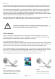
• IC2: SFH5110-36 Infrared-receiver-IC, bend the legs with long-nose pliers!
Pay attention to polarity (the side with dome-shaped curvature must be positioned to the
outside)! Caution: electrostatic discharge (ESD) and excessive soldering or heating may
damage the part!
• D10: SFH 415-U IR-LED 5mm; black case; Pay attention to polarity! Case must be settled
close to PCB.
• T11, T12: LPT80A, Phototransistor, colorless case;
Case must be settled close to PCB; Pay attention to polarity!
• D13, D14: IRL80A, IR-LED, rosy case;
Case must be settled close to PCB; Pay attention to polarity!
• D15, D16: LED 5 mm red, rosy respectively red case. Pay attention to polarity
(short leg must be inserted at the mark)!
• S1: On/Off-Switch
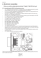
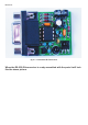
Electronics