
User manual


ASURO - 17
-
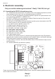
The following inserting sequence may be used as a guideline:
• IC1: at rst insert only the socket (either one Dual in line 28 pole-socket or two Dual in line
14 pole-sockets). Pay attention to polarity! A slight asymmetry is a mark for polarity in the
socket and in the symbols on the PCB!
• IC3: Again insert only the socket (Dual in line 14 pole-socket). Pay attention to polarity! A
slight asymmetry is a mark for polarity in the socket and in the symbols on the PCB!
• K1, K2, K3, K4, K5, K6: Sensor-switches, which must be mounted at to the PCB surface!
• Q1; Resonator 8MHz
• D1, D2, D3, D4, D5, D6, D7, D8: Diode 1N4148; Pay attention to polarity!
• D9: 1N4001; Pay attention to polarity!
• JP1: Jumper; Short pins will be soldered, do not yet apply the jumper connector element!
• D12: Dual colored LED, 3 mm diameter, three legs ; Pay attention to polarity! (polarity may
differ from part to part, however: the shortest leg must be inserted into the square soldering
pad)!
• C2, C3, C4, C5: 100nF Ceramic; Imprinted: 104
• C6, C7: 4,7nF Ceramic; Imprinted: 472
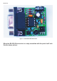
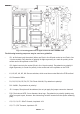
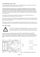
Fig. 4.2: Inserting parts view of upper-side to the main ASURO-PCB
Electronics
Electronics