
User manual


ASURO - 16
-
4.3. Inserting parts in the ASURO-PCB
The two longer axles, which will be needed for the second gear section are to be soldered or glued
at the bottom-side of the PCB. Soldering is the best option, it hardens much faster than gluing and
you always can easily correct it afterwards when necessary.
The two shorter axles have to be attached at the upper PCB-side nearer to the middle of the
board. Before attachment, the axles must be cleaned at the soldering or glue-side (but not at the
wheel-side) with some very ne sandpaper (corning number 240 or more), in order to improve
adhesion of the solder respectively glue. If you choose soldering these parts, the following
procedure should be followed:
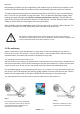
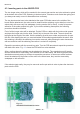
First of all the longer axles will be attached. Put the PCB on a table with the bottom side upward
and place the longer axle into the slide. Push it fully to the end of the slide. The axle should be
laying at at the length of the slide. Wet the soldering tip with some solder and press the tip onto
the axle. After heating the axle you must add solder at the soldering pads beside the axles. After
the soldering is nished, the soldering iron can be removed, while pressing the axle downwards
with a screwdriver until the soldering connection is cooled off completely.
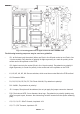
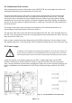
Repeat the procedure with the second long axle. Turn the PCB around and repeat the procedure
with both short axles. Fig. 4.3 shows the PCB with four axles attached.
After a cooling phase the wheels may be attached to the axles. The cogwheels must t exactly
and the wheels are to rotate easily. If the wheels do not rotate easily, the axles might have been
attached erroneously and you will have to repeat the procedure. In case some solder fractions
should be attached to the surface of the axles in the wheel area, they must be removed by
sandpaper or with a ne le.
If the wheels rotate easily, they may be removed and be put aside in order to place the electronic
parts onto the PCB.
Fig. 4.3.:
ASURO-PCB with attached axles
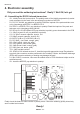
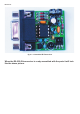
Electronics