
User manual


ASURO - 11
-
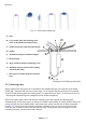
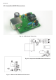
Fig. 3.3 : Parts with bended legs
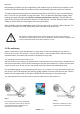
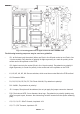
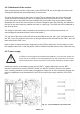
Fig.
3.4:
Creating a neat soldering connection
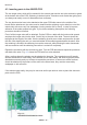
3.3. Soldering parts
After preparing the legs, parts are to be tted in the metallized holes of the printed circuit board
(PCB) and – for parts with only two or three legs – to be spread. Bending the leg at the backside
of the PCB will prevent parts from falling down. For parts with more legs – eg. the sockets for ICs
– bending two opposite legs on a diagonal line will suf ce completely.
After xing a part, apply some heat with the soldering tip to the leg and the soldering pad
simultaneously. At the same time you will have to add a small quantity of solder. While melting, the
solder will ow into the metallized hole. Add some more solder until the hole is lled completely
(see g.
3.4).
Now remove the solder and then the soldering iron. Do not move the part or the
PCB until the connection has chilled and become rigid. Moving parts while chilling will result in
unreliable contacts, causing intermittent failures.
Electronics
A. Part
B. Leg, solder pad, and bending area
have to be heated simultaneously
C. Solder must ow into the drilling hole
D. Solder
E. Round bending area without edges
F. Soldering tip
G. Neat, vulcano-shaped soldering cone
H. Bending legs to prevent parts falling
out from the PCB
I. Bend area at some distance from the
part
A
I
H
F
F
B
B
C
G
G
E
D
D
D