Licence by DLR ROBOT KIT © DLR Germany and AREXX - The Netherlands ASURO Assembly and Operation MANUAL Model ARX-03 Manufacturer AREXX, Zwolle - NETHERLANDS JAMA, Taichung - TAIWAN www.arexx.
Introduction ASURO is a mobile mini-robot, completely programmable in C and especially developed for education at the German Aerospace Centre DLR, department for Robotics and Mechatronics. Assembly is easy for experienced electronic technicians and feasible for a novice. Except for the printed circuit boards (PCB) only standard parts for assembly will be used. For programming we use freeware only.
CONTENTS I. Mechanics 6 1. Necessary tools 6 2. Mechanical preparations 2.1. Motorpinion 2.2. Table-tennis ball 2.3. Axles 2.4. Wheelsenors 7 7 7 8 8 II. Electronics 9 3. Soldering instructions 3.1. Tip, solder and temperature 3.2. Preparing parts 3.3. Soldering parts 3.4 De-soldering 9 9 10 11 12 4. Electronic assemly 4.1. Assembly RS232-Infrared-Transceiver 4.2. Optional USB-Infrared-Transceivers 4.3. Assembly ASURO-PCB 4.4. Attachment of the motors 4.5. Power supply 13 13 15 16 20 20 5.
6. Trouble shooting 28 6.1. Failure of RS232-IR-Transceiver ! 6.1.1. Activated key and displayed symbol do not match 6.1.2. The Terminal-Programm does not display any symbol 6.1.3. Still not working 6.2. USB-Infrared-Tranceiver does not work 6.3. Back-LEDs (D15,D16) glimmen nach dem Einschalten nicht! 6.3.1. Back-LEDs do not glow at start up 6.3.2. Only one of the back LEDs is glowing 6.3.3. Status-LED (D12) is not activated biocolored after start up 6.4. A display does not work 6.4.1.
III. Software 35 8. 8.1. 8.1.1 8.1.2 8.1.3. 8.2. 8.2.1. 8.2.2. 8.3. 8.4. 8.5. 35 35 35 35 39 51 51 52 53 54 54 Software installation and initial steps WINDOWS Installation Flash - the ASURO-Programmer-Tool Installation of the editor and compiler Example programs LINUX Installation Flash - the ASURO-Programmer-Tool Compiler Working with Flash Flash failures First step in Programming 9. C for ASURO 56 9.1. Basics in C-Programmierung 9.1.1. Introduction 9.1.2. Variables and datatypes 9.1.3.
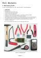
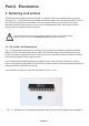
Part I. Mechanics 1. Necessary tools In order to build the ASURO we need – apart from the kit – the following tools: • • • • • • • • • • • • A „third hand“ Stanley-Knife Small hammer Sandpaper (for fine work, Nr. 240) Long nose plier for electronic work Cutter for electronic cable work Soldering iron for electronic work (approx.
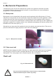
Mechanics 2. Mechanical Preparations Completeness of the kit must be checked first. A parts list in appendix A has been provided as a checklist. Before doing any electronic artwork, we must however do some mechanical preparations. So let’s start working. 2.1. Motorpinion Motor power is to be transmitted to the gear by small cogwheels (with drilling holes of 1.9 mm), which have to be pressed onto the motor axles.
Mechanics 2.3. Axles Axles are manufactured from a brass rod. Two pairs of axles are needed, each with a length of 24.5 mm and 42.0 mm respectively. These axes are suplied in correct length with this kit. 2.4. Wheel sensors The odometer, consisting of a light emitting diode and a phototransistor, looks forward to the black and white markers on the 50/10 cogwheel. A complete set of adhesive odometer markers is supplied with this kit. Place them on to the 50/10 gear as shown in fig. 2.3.
Part II. Electronics 3. Soldering instructions ASURO has been designed with wired parts (in contrast to the much smaller surface mounted devices). Fig. 3.1 demonstrates the smallest available package for the ASURO processor IC and the wired device we have incorporated. The chip inside these devices however is the same! Although soldering wired devices is much more comfortable and easier, especially untrained persons have to consider some precautions.
Electronics DANGEROUS END ! Fig. 3.2.: Basics for soldering While soldering, some smoke will be generated which may cause damage to your health. Avoid breathing gases or work under a cooker hood. Using solder for non-electronic use and using resins may destroy components. 3.2. Preparing parts While soldering small parts you will need some tricks and tips to reach the soldering area.
Electronics Fig. 3.3 : Parts with bended legs A. Part B. Leg, solder pad, and bending area have to be heated simultaneously B F C. Solder must flow into the drilling hole H D G D. Solder C E. Round bending area without edges F. Soldering tip A G. Neat, vulcano-shaped soldering cone H. Bending legs to prevent parts falling out from the PCB I. Bend area at some distance from the part I E Fig. 3.4: Creating a neat soldering connection 3.3.
Electronics Bad soldering contacts may be recognized by ball-shaped slugs of solder around a pad or a mat surface (for lead-less solder the surface will even be extremely mat) and must be re-soldered. To insert sockets and other parts for horizontal mounting on the PCB you may use the following trick: First of all you just solder one leg of the part. Then you press the part down slightly, while heating the same soldering pad (Caution: the part may become very hot).
Electronics 4. Electronic assembly Did you read the soldering instructions? Really? Well OK, let’s go! 4.1. Assembling the RS232 infrared-transceiver • • • • • • • • • • • • • • • • • IC1: Initially insert the 8-pole socket. The polarity mark of the (slightly asymmetrical) socket must correspond to the mark in the accompanying symbol on the PCB. D1, D2, D3: 1N4148, pay attention to polarity! Read the imprints of the parts and take care not to interchange with ZPD5.1 or BZX55-C5V1! D4: ZPD5.
Electronics fig. 4.1.: Assembled IR-Transceiver When the RS-232-IR-transceiver is ready assembled with the parts it will look like the above picture.
Electronics 4.2. Assembled USB IR-transceiver Fig. 4.2.: USB Infrared-Transceiver Fig. 4.3.: Component side USB Infrared-Transceiver Fig. 4.4.
Electronics 4.3. Inserting parts in the ASURO-PCB The two longer axles, which will be needed for the second gear section are to be soldered or glued at the bottom-side of the PCB. Soldering is the best option, it hardens much faster than gluing and you always can easily correct it afterwards when necessary. The two shorter axles have to be attached at the upper PCB-side nearer to the middle of the board.
Electronics Fig. 4.2: Inserting parts view of upper-side to the main ASURO-PCB The following inserting sequence may be used as a guideline: • IC1: at first insert only the socket (either one Dual in line 28 pole-socket or two Dual in line 14 pole-sockets). Pay attention to polarity! A slight asymmetry is a mark for polarity in the socket and in the symbols on the PCB! • IC3: Again insert only the socket (Dual in line 14 pole-socket).
Electronics • T1, T3, T5, T7: BC327-40 or BC328-40 • T2, T4, T6, T8: BC337-40 or BC338-40 • R1, R2, R3, R4, R5, R6, R7, R8, R19, R21, R24: 1kΩ (brown, black, red, gold) • R9, R16: 220Ω (red, red, brown, gold) • R10, R17, R22, R31: 470Ω (yellow, violet, brown, gold) • R11: 100Ω (brown, black, brown, gold) • R12: 12kΩ (brown, red, orange, gold) • R13: 10kΩ (brown, black, orange, gold) • R14, R15: 20kΩ (red, black, orange, gold) • R18, R20: 4,7kΩ (yellow, violet, red, gold) • R23: 1MΩ (br
Electronics Three more parts will be needed (which will be used to follow a line), but they will be placed at the bottom side of the PCB and have to soldered from the upper side (see fig. 4.5): • T9, T10: SFH300, Phototransistor 5 mm; Pay attention to polarity! These components have to be placed at some distance from the PCB. • D11: LED 5 mm red, red or reddisch case; Pay attention to polarity! (short leg must be inserted at the mark)! Fig. 4.
Electronics 4.4. Attachment of the motors After completing the insertion of the parts on the ASURO-PCB, we must supply the motors with cabling and attach these parts temporarely for some tests. To supply electrical energy to the motor, we need 70 mm red and black wire for each terminal. These four wires for two motors have to be stripped at both ends for around 4 mm. The ends of the wires have to be twisted and pre-soldered with some solder.
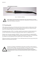
Electronics 5. Preparation for operation After completing the assembly we will start moving the robot. But first we will have to find and eliminate the errors we could have made in the previous phase, without destroying any parts. 5.1. RS232-Infrared-Transceiver The following operational check is limited to the RS232-Infrared-Tranceiver (Fig. 4.8). First of all the IR-Transceiver must be checked, as it will be needed for the next step: the selftest of the system.
Electronics 5.2. USB-Infrared-Tranceiver This operation is only for the USDB IR-Transceiver. WARNING! The USB IR-Transceiver does not have a housing and therefore it is very sensitive for electrostatic discharge. Before you use it, discharge your body by touching a metal computer housing or other earth point. An other option is to build the USB IR-Transceiver in a transparant housing for further protection. 5.2.1 Windows The following operational check is limited to the USB Infrared-Tranceiver.
Electronics 5.2.2 Linux The following operational check is limited to the USB Infrared-Tranceiver and LINUX software. First of all the IR-Transceiver must be checked, as it will be needed for the next step: the selftest of the system. For this test connect the IR-Transceiver to a free USB port of your PC by a USB extension cable. A short beep will confirm that the transceiver was detected by the LINUX software. To be sure please check in the proc-declaration if the following message is displayed.
Electronics 5.3. ASURO operation Caution: The processor (IC1) is not to be inserted yet! Now be careful and turn the main switch ON. Both back-LEDs (D15, D16) should be glowing dimly. If they do not glow dimly, pleasy switch off the system immediately and continue reading in chapter 6.3. If you are succesful, switch the system OFF and insert IC1 (Processor) and IC3 (AND Gate) (see fig. 5.1).
Electronics Now insert the Jumper (J1) for recheargable devices. The polarity marks of the ICs must align with the marks of the sockets and the marks on the PCB. The processor has been designed to do a selftest and it will check all components on power up. Just to avoid any difficulties in this phase, you are advised to read the next chapter completely before switching power ON and then return to this chapter. At this point we start testing.
Electronics 5.3.3. Switches ASURO is immobile and all displays are dark. That is a good omen! Now we are ready to check the switches for about 15 seconds. Just hit the switches, to see if something happens.
Electronics If an optical connection between ASURO and the Infrared-Transceiver has been arranged (which requires a maximal distance of ca. 50 cm), the terminal program will show up a symbol ‘T’ regularly or alternatively the button you may have activated at the PC’s keyboard (as it has been transmitted by the transceiver), followed by the symbol next in the alphabet, eg.
Electronics 6. Error tracing 6.1. Failure of the RS232-IR-transceiver 6.1.1. Activated key and displayed symbol do not match Calibrate Trimmer TR1 until activated key and displayed symbol do match. 6.1.2.
Electronics 6.3.2. Only one of both back-LEDs is glowing Did you insert the diodes (rose- or red-colored), D13 (left) ,D14 (right), and the phototransistors (transparent or black case) T11 (left), T12 (right) at the correct position and with the correct polarisation? Check the value for resistors R18, R19 (left) and R20, R21 (right)? 4,7KΩ (yellow, violet, red, gold) 1KΩ (brown, black, red, gold) Have these parts been inserted at the correct position? (check the imprint on the PCB!). 6.3.3.
Electronics 6.4.3. Left back-LED D15 does not work Check polarisation of LED D15. Check resistors R19, R18. 1KΩ (brown, black, red, gold) 4,7KΩ (yellow, violet, red, gold) A simple check may be done the following way: remove the processor (IC1) and connect by wire Pin7 (VCC) and Pin24 (left back-LED will be activated red). If this test is succesful, (1) either the processor may be defective, or (2) a track of the PCB may be broken / interrupted. 6.4.4.
Electronics 6.6.2. The display reacts as if switches have been interchanged Resistors to the switches have been interchanged Check R24, R25, R26, R27, R28, R29, R30, R32 as well! 1KΩ (brown, black, black, brown, brown) 2KΩ (red, black, black, brown, brown) 8,2KΩ (grey, red, black, brown, brown) 16KΩ (brown, blue, black, red , brown) 33KΩ (orange, orange, black, red, brown) 68KΩ (blue, grey, black, red, brown) 6.6.3. Things still do not work well Check R23, R24.
Electronics 6.8. One motor does not move 6.8.1. Both motors do not move Check polarity and position of IC3. 6.8.2. The left motor does not move or only in one direction In this case the complete motor bridge, consisting of transistors T1, T2, T3, T4 (did you insert the correct transistors at the correct positions?), the diodes D1, D2, D3, D4 (polarity!) and resistors R1, R2, R3, R4. BC327-40 or BC328-40, BC337-40 or BC338-40, BC327-40 or BC328-40, BC337-40 or BC338-40 1KΩ (brown , black, red, gold) 6.8.2.
Electronics 6.9.3. Things still do not work well Check polarity of C8. 220µF/ at least 10V If transfer of data between PC and ASURO is malfunctioning again and again, re-adjust trimmer TR1 in the transceiver. Instant and bicomponent glues are suspected to cause irritant and allergic reactions at skin exposure. Any exposure to these materials must be avoided. Vinyl gloves may protect your hands.
7. Final adjustments Grease the axles slightly. Place the cogwheels with its fine black and white markings onto the short axles. The tires combined with the cogwheels are now placed onto the long axles and secured by a locking ring. Move the motor, which has been fixed temporarely, carefully until it has been adjusted properly, the cogwheels fit together properly and the transmission system runs smoothly. (Run the selftest completely to see if the motors in the transmission are working well).
PART III. Software 8. Software installation and initial steps Insert the ASURO CD. When all is OK it will start automaticaly otherwise open it with windows explorer. After the language selection you will find all the programs you need for the ASURO under the software menu. Before you can work with them you have to install the program on your hard drive first.
Software Now this screen will show up: Click [I Agree] This screen appears: Click [Next] ASURO - 36 -
Software The next screen appears: Click [Install] and the next screen appears: Wait… ASURO - 37 -
Software …till the programmers Notepad 2 (PN2) editor with the README.txt screen appears. Close the screen ‘programmers notepad 2’. On the DESKTOP the ‘programmers notepad 2’ Symbol appears: The program editor and the compiler are installed now.
Software 8.1.3. Copying the example programs from CD to the harddisk. Copy the folder ‘ASURO_src’ from the ASURO CD to the hard disk (put it in a folder something like this: ‘C:\ASURO_src’). When the data source is secured, click with the right mouse button on the file, go to properties and deactivate the security. Setup a menu input for the compiler in the program editor. Open programmers Notepad 2’ (click twice on the notepad symbol on your desktop): In menu Tools | Choose options.
Software Select on the rigth side ‘C/C++’. ‘C/C++’ is selected.
Software The window ‘New Tool’ appears. Type the following or select it with the Browse-button : Name: make Command: C:\ASURO_src\FirstTry\Test-all.bat Folder: C:\ASURO_src\FirstTry Click [OK] A new PN2-tool with the name “make” is now available in the tools main menu. (When we activate this tool, it will run a batch file with the name Test-all.bat, now the compiled data will be placed in the folder C:\ASURO_src\FirstTry).
Software Setup a clean file In the program editor menu.
Software The window ‘New Tool’ appears; Type the folowing or select it with the Browse-button : Name: clean Command: C:\ASURO_src\FirstTry\Test-clean.bat Folder: C:\ASURO_src\FirstTry Click [OK] A new PN2-tool with the name “clean” is now available in the tools main menu. (When we activate this tool, it will run a batch file with the name Test-clean.bat, now the compiled data which was placed in the folder C:\ASURO_src\FirstTry) will be removed.
Software In the options-screen, under tools, you will now find the make and clean files which we have made in the previous steps.
Software Just for try we will open the file ’C:\ASURO_src\FirstTry\test.c’ : Click [Open].
Software File test.c will be opened. When you choose tools… …you will find the new tools make and clean in the menu bar. Click on make.
Software The file test.c (together with asuro.c) will be compiled now… …and when the program does not contains any mistakes (what could be expected, because we just loaded an example program), on the bottom this message will appear: Errors: none. What happened? From the file test.c (and asuro.c) a new file test.hex was generated. This file contains the in machine code converted program. This machine code program can be loaded (flashed) in ASURO’s memory. This program does not have a function.
Software The make file in our example program is written in a way that a file with the name test.c will be compiled together with asuro.c (which contains some pre defined functions) and create a new .hex-file. This file can be loaded (flashed) into the ASURO memory. Attention! This means that - as long you do not change the make file and you only copy it - you should always name your own program test.c .
Software When you open it.… …you will see all the generated data files… (Click [Cancel]) …and after you run the “clean“ command..
Software …you will see… …that a lot of the generated data files are removed. What did happen? The menu input “clean” calls for the batch file Test-clean.bat. Make started this with the parameter “clean”. Now the input in the make file is executed in the name of clean and all data files which are not necessarry anymore will be removed.
Software 8.2. LINUX For the software installation you need root rights. If you do not have this log out and log in again as root or open a shell and demand the root with ‘su’. 8.2.1 Flash - The ASURO-programming-tool Start the program from the CD software menu and copy the two flash tools “asuroflash” and “asurocon” from the folder “/linux/tools” into the folder “usr/local/bin”. After this, you must alow the execution of the program with “chmod a+x/usr/local/bin asurocon and asuroflash. Fig. 8.1.
Software 8.2.2 Compiler To instal the Gnu-Compilers for AVR-Processors insert the ASURO-CDROM choose from the folder “/Linux/Compiler/” the folowing: 1. avr-binutils-... .rpm 2. avr-gcc-... .rpm 3. avr-libc-... .rpm The Installation is quite simple! Just give the command: rpm -i .rpm in your root directory. Ready! For Editors you can use Exmacs, Kate or Kedit. For trial you can copy the demo programs from the CD.
Software 8.3. Flash - The ASURO-programming-tool In this step we will need the Flash-Program (see fig. 8.3). Fig. 8.3.: Flash-Tools for Windows and LINUX) Start the program and select the interface in which you have plugged the IR-Transceiver. Select Test.hex from directory C:\Own files\ASURO_src\FirstTry. Place the completely assembled and tested ASURO near the IR-Transceiver, at a distance of max. 50 cm. The component sides of both PCBs must be facing and “seeing” each other.
Software 8.4. Flash failures The following errors may occor while flashing: “c” “t” “v” Checksum Error. ASURO has received some irregular signals. Signals may have been disturbed by other optical sources, such as fluorescent lights, or have been interrupted shortly by movements. Timeout. The line-of-sight between ASURO and the IR-Transceiver has been interrupted completely. Verify Error. ASURO wrote invalid data into its Flash-memory.
Software If the compiler displays another message, you will have to trace the error by analysing the source code. It is a good idea to look at the first line in the source, in which errors have been reported. The editor displays the line number in the source in the left bottom corner of the display window. After a succesful translation you may deliberately alter a word in the program source. Restart the make procedure and check, in which line number the “error” has been reported.
9. C for ASURO This chapter is devoted to the programming language C, but explanation will be limited to the elements which are needed to control the ASURO system. Obviously the explanation is not a complete C-manual, for which other literature may be found on the market1. C has been chosen for its widespread standard and because a C-Compiler is available for almost every processor.
C for ASURO If we want to place a comment between programming lines, the set of comment words or lines starts with “/*” and ends with “*/ ”. A single line may also be defined to be a comment by starting the line with “//“3. Transforming programming lines into comments is often used to exclude parts of the program from being processed. The compiler will ignore all comments. Correctly inserted comments will never cause problems in program execution. 9.1.2.
C for ASURO Declaration of variables may be provided as global variable outside the main()-function or as a local variable inside the main()-function. Global variables will be valid in the complete program area. Local variables will be valid inside the main()-function or any other function only. They will be valid for the programming code inside the function and they will be invalid outside the function. Variables are rather useless, as long as we are unable to fill them with data.
C for ASURO 9.1.3. Compiler directives You may have wondered about the first program line #include “asuro.h”. This #include-directive defines an inclusion of an external source code into your program and orders the compiler to include the textfile in the compiler sequence. Our include-file contains some functions, which will be needed for robot operations. Another important directive (amongst others, which are lying beyond the scope of our introduction to C) is the so called text replacement.
C for ASURO If the program should be able to choose one option out of several alternatives, you may use several “else if”-constructs.
C for ASURO 9.1.5. Loops Loops are to be used to repeat command execution. In a “while”-loop a condition is checked every time the loop is passed. If the condition is true the command block will be executed. The condition is checked again until it turns to false. At a false condition the program is continued at the first command following the condition block. while( Condition) Command block Example: #include “asuro.
9. C für ASURO “while(1)” is equivalent to “for(;;)”, and both are eternal loops as the abort condition (in this case a value 0) will never be reached. Another loop sequence is a “do”-loop do command block while( condition); In contrast to a “while”-loop the condition will be checked after the command block. This programming sequence forces the command block to be executed at least one time. 9.1.6.
C for ASURO Now after some theory on data types and functions we would like to build a simple function, multiplicating two 8-bit numbers and returning the result.
C for ASURO 9.1.7. Pointers and vectors Pointers and vectors will be described to an extent, needed for the ASURO-operations. If we need to track data from the line tracing sensors or odometric sensors we will need vectors. Their declaration is rather simple: int lineData[2]; int odometrieData[2]; As you will recognize we will create two vectors (lData, oData) with 2 elements for linetracing and for odometrics.
C for ASURO To receive characters, ASURO uses a function SerRead (). The first parameter contains a variable in which the received characters are to be stored. The second parameter defines how many characters will be received and the third parameter defines a timeout: if within a certain time period (a number of processor clock cycles) no data has been received the SerRead () -function will be aborted. By using a number “0” however, the function will wait until all characters have been received.
C for ASURO 9.2.1. void Init(void) This function will reset the microprocessor to its initial state and must always be executed at the beginning of a program. If the function is missing, the processor does not even know, what to do with its terminals. A simple ASURO program should at least look like: #include “asuro.
C for ASURO 9.2.3. void FrontLED (unsigned char status) The Front-LED (D11) will be switched ON or OFF. Valid parameters are ON respectively OFF Example: The front-LED will be switched on by: FrontLED(ON); 9.2.4. void BackLED (unsigned char left, unsigned char right) The Back-LEDs (D15 and D16) will be switched ON or OFF. The first parameter describes the state of the left back-LED (D15) while the second parameter describes the state of the back-LED at the right side (D16).
C for ASURO 9.2.7. void MotorSpeed (unsigned char left_speed, unsigned char right_speed) This function controls the motor speed for both engines. Maximum speed is 255 (unsigned char). The motor will start rotating at a value of around 60, depending on mechanical conditions. The parameter value in fact controls motor power and the rotational speed also depends on other factors like friction or inclination in slopes. As soon as this function has been executed ASURO will start moving.
C for ASURO Example: The string „Go Ahead“ should be received and we want to be sure all characters do have arrived at the ASURO before we continue operation. #include “asuro.h” int main(void) { char data[8]; Init(); SerRead (data,8,0); MotorDir(FWD,FWD); MotorSpeed(120,120); while(1); return 0; } . . . // allocate storage // Read data // Eternal loop 9.2.10. void LineData(unsigned int *data) This function has been developed to read the light intensity of both phototransistors at the bottomside of ASURO.
C for ASURO Of course you would like an example as a complete program: #include “asuro.h” int main(void) { unsigned int data[2]; Init(); FrontLED(ON); MotorDir(FWD,FWD); while(1){ // Line tracing the easiest way // Allocate storage // Switch ON line trace illumination // Both engines go ahead // Eternal loop, ASURO should follow // a line eternally LineData(data); // Read brightness data from Phototransistors if (data[0]>data[1]) // left brighter than right {MotorSpeed(200,150);} // ...
C for ASURO 9.2.12. unsigned char PollSwitch (void) This function scans the position of switches (K1-K6) and returns one byte, containing information, which switches have been activated. Switch 1 will set the first bit number 5, switch 2 will set the second bit, ... switch 6 will set bit number 5, Bit0 (1) -> K6 Bit1 (2) -> K5 Bit2 (4) -> K4 Bit3 (8) -> K3 Bit4 (16) -> K2 Bit5 (32) -> K1 Activating switches 1,3 and 5 will cause the function to return 42 (32+8+2 = 42).
Part IV. Appendices A.
Appendices A. Partlist 4x Cable binder 1x Cable binder releaseable 2x Rubber tires 38mm 2x Messing shaft 42mm long 3mm diameter, 2x Messing shaft 24,5mm lang, 3mm diameter ca. 15 cm wire red 0,14mm_ ca. 15 cm wire black 0,14mm_ 2x Encoder sticker (see 2.4) The additional RS-232-IR-transceiver will be equipped with the following parts: 1x Printed circuit board IR-RS232-transceiver 3x Diodes 1N4148 1x Zenerdiode ZPD5.
Appendices B.
Appendices C.
Appendices D.
Appendices E. Block diagram ASURO F.
Appendices G.