
Use and Care Manual

v.201016 11
ENGLISHENGLISH
ASSEMBLYASSEMBLY
STEP 5STEP 5
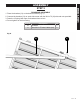
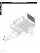
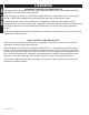
DRAWBAR ASSEMBLY
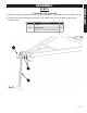
1. Place the drawbar (31) on the beds as shown (Fig. 6)
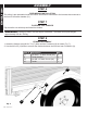
2. Connect the drawbar (31) on each side runner with the M14 x 70 (6) bolts and nuts provided.
3. Draw the L-Spring latch open for drawbar tubes to lock.
4. Do not tighten for the time being.
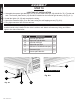
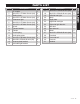
Item N
o.
Description Qty.
31 Drawbar 1
6 Hex M14 x 70 nuts & bolts (set) 2
631
Fig. 6