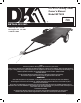
4 ft. x 8 ft. Folding Trailer Owner’s Manual Model MFT4X8 8 ft. (244 cm) Utility Trailer DETAIL K2 INC. 1080 Clay Ave., Unit #2 Burlington Ont. L7L 0A1 1-888-277-6960 STOP! Questions, problems, missing parts? Do not return to your retailer. Please call our customer service department at: 1(888) 277-6960. Our customer service staff are ready to provide assistance. If a part is damaged or missing, replacement parts can be shipped from our facility.
ENGLISH WARNING! Please read through these instructions completely BEFORE you begin to assemble and install your DK2 trailer. Failure to follow the instructions closely could cause serious personal injury or property damage. Thank for very much for choosing a DK2 product! For further reference, please complete the owner’s records below: Model: _______________ Purchase Date: _______________ Save the receipt, warranty and these instructions.
IMPORTANT SAFE OPERATING PRACTICES ENGLISH IMPORTANT: Read safety rules and instructions carefully before using this equipment. Read and follow instructions carefully. Save owner’s manual for future reference or parts information. Be certain any future user of this carrier is aware of correct attachment and use. CAUTION: Safety First — Read this manual carefully before attaching and using your trailer.
ENGLISH GENERAL WARNINGS WARNING: Read and understand all instructions. Failure to follow all instructions listed below may result in electric shock, fire and/or serious injury. WARNING: The warnings, cautions, and instructions discussed in this instruction manual cannot cover all possible conditions or situations that could occur. It must be understood by the operator that common sense and caution are factors that cannot be built into this product, but must be supplied by the operator. 1.
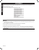
GENERAL WARNINGS UNPACKING z When unpacking, check to make sure all the parts shown on the Parts List (see p. ) are included. z If any parts are missing or broken, please contact with us. TECHNICAL SPECIFICATIONS Tires Wheel Lug Nuts Tire Pressure Rim Bed Dimensions Ball/Coupler size Coupler capacity Load Capacity Net weight GAWR GVWR 5.30-12 tubeless 5 per wheel: 85-90 ft-lb. (115.24 - 122.02 Nm) torque 80 PSI (552 kPa) cold 12 x 5 4 ft. x 8 ft. (1.22 m x 2.44 m) 2 Inch (≈ 50 mm) Class II; 3500 lb.
ENGLISH ASSEMBLY Read the following instructions step by step. Refer also to the complete parts and hardware list. Average assembly time is 1 hour. You will need the following tools to assemble your trailer: 16 mm wrench or socket 17 mm wrench or socket 18 mm wrench or socket 19 mm wrench or socket 20 mm wrench or socket 21 mm wrench or socket Pliers Phillips screwdriver Rubber mallet NOTE: z The trailer parts are called out by standing at the rear of the trailer looking toward the hitch.
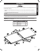
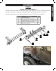
ASSEMBLY BED ASSEMBLY Lay the front bed (26) and rear bed (21) as shown. Note the location of the marker lights holes in the front side rails. See fig.1 1. Use M10 x 20 hex head bolts and nuts (34) to mount the 8 stake pockets (40) to the trailer as shown. 2. Use M10 x 20 hex head bolts and nuts (34) to mount the inside hinge (27) to the front bed (26) and the outside hinge (28) to the rear bed (31); NOTE: Do not join the hinges from front to rear bed halves yet. 3.
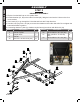
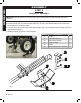
ENGLISH ASSEMBLY STEP 2 1. 2. 3. 4. 5. DRAWBAR ASSEMBLY Flip the front bed half over so it is upside down. Position drawbar (5L, 5R) to the trailer front bed (26), fitting the bars into the U slots on the front cross member. Use L latch (37) to go through the U bracket and lock with R clip after then. Use M10 x 30 (36), M12 x 25 (39) to connect the drawbar end to trailer side rails. Do not tighten the bolts until all bolts in position.
ASSEMBLY ENGLISH STEP 3 SPRING HANGER ASSEMBLY Install the Left spring hanger (19) and Right spring hanger (shown, 41, fig.3) to trailer sides with M10 x 20 (34) at front, M10 x 30 (36) in the middle and M10 x 25 carriage bolts (35) for rear end. (35) insert finger tight for later in the assembly process, this will secure your bed halves Item No.
ENGLISH ASSEMBLY STEP 4 FENDER KIT ASSEMBLY NOTE: You will have to prop up the bed to give yourself space to attach fender and caster bracket. 1. Connect the fender bracket (24) to spring hangers (19,41) with M10 x 20 bolts and nuts (34). 2. Connect fender (25) to fender bracket with M10 x 20 (34). Note that the holes on the side of the fender edge are toward the trailer. 3. Connect left caster bracket (22) to left spring hanger (19). Connect Right caster bracket (23) to the right spring hanger(41). 4.
ASSEMBLY SPRING AND AXLE ASSEMBLY 1. Place 3 leaf spring (8) into spring hanger with eye forward, towards the drawbar of the trailer. Install M14 x 85 (9) go through spring hanger, and spring eye and lock with M14 nyloc nut. 2. Install M14 x 85 go through spring tail and spring hangers and lock with M14 nyloc nut. 3. Place Axle (7) onto spring (8) with hole in axle over peg on spring. Fasten Axle to each spring with two U bolts (9), spring plate (6) and lock with four M10 nuts as shown. Item No.
ENGLISH ASSEMBLY STEP 6 TIRE ASSEMBLY 1. Locate both tire/hub assemblies. For easy access, be certain thatgrease fittings are facing out away from the hub as shown in figure 6-1. 2. Remove hubcap (21) using a small pry bar between the flange on the hub cap and the face of the hub (fig.6-2a). 3. Remove 4 mm cotter pin (L), bearing (20) and washer (N). See figure 6-2b. 4. Remove castle nuts (H) from axle ends. 21 �ig.6-1 �ig.6-2b �ig.6-2a 5.
ASSEMBLY �ig.6-4 ENGLISH 6. Install outer bearing (fig.6-3, 11) with the taper facing inward toward the hub. 7. Install the washer and castle nut (fig.6-3, 14 & 15). Tighten castle nut while turning the tire/hub. Tighten castle nut until there is resistance while turning the tire/hub. 8. Install 4 mm cotter pin (fig.6-4, L) through castle nut (fig.6-4, H) and hole in axle end. If holes are not aligned, slightly loosen castle nut -no more than one castellationto align holes. 9.
ENGLISH ASSEMBLY STEP 7 GETTING YOUR TRAILER TOW READY 1. Lay the rear bed upside down on the front trailer bed 2. Fasten the brackets together using the M10 x 20 (34) on both sides 3. Carefully flip the rear trailer bed down as shown in fig. 7-1 NOTE: two (35) and two (34) can be inserted to join your bed halves and have your trailer tow ready. �ig.6 �ig.
ASSEMBLY LIGHTING KIT INSTALLATION 1. Attach the Light Brackets (33) to the Rear Left Side Rail and Rear Right Side Rail by using four sets of M10 x 20 Bolts and M10 Nuts (44). 2. Attach the License Plate Bracket (29) with the Left Tail Light (30L) to the Light Bracket on the Rear Left Side Rail, using M10 Nuts. 3. Attach the Right Tail Light (30R) to the Light Bracket on the Rear Right Side Rail, using M10 Nuts. 4.
ENGLISH ASSEMBLY STEP 9 WIRING THE TRAILER NOTE: Only a qualified technician should perform the electrical service that may be needed to enable your particular make/model vehicle to power the Trailer’s 12 volt DC lighting system. This is beyond the scope of this manual.
ASSEMBLY ENGLISH 4-pin connector White ground wire to trailer tongue Brown Yellow Brown Side marker lights Green Black Wire clip Yellow Brown Brown Brown tail lamp wires Left light (Yellow lead) �ig.8-2 Right light (Green lead) Wired same as left side KEY / COLOR CODES Brown: Tail and side marker lights Green: Right directional and stop light Yellow: Left directional and stop light White: Ground to trailer frame O Indicates wire nut connection v.
ENGLISH ASSEMBLY 3. Connect the brown wire to the vehicle’s left tail light by stripping, wrapping, and taping the connector plug. 4. Connect the yellow wire to the vehicle’s left signal and stop light wire. 5. Connect the green wire to the vehicle’s right signal and stop light wire. 6. Attach the white ground wire at the plug end of the wiring harness to the small mounting hole in the Tow Bar (5) with a 1/4” (6 mm) tapping screw (not included). See J, fig.8-3. �ig.8-3 7.
ATTACHING THE COUPLER 1. Attach the Coupler (2) to the Coupler Base (4), using two sets of M12 x 75 bolts (20b) and M12 nuts (20n). When installing the front bolt, thread it through the center link of the Safety Chain (1) to secure the Chain to the Coupler. Latch Trigger 2.Item Lock Trigger, using its Locking No.the CouplerDescription Qty.Pin and R-Clip. 1 2 20 Safety chain 2 inch coupler Hex bolt M12 x 80 & nut (set) 1 1 2 R Clip fig.9-2 Safety Pin b n �ig.9-1 3.
ENGLISH ASSEMBLY WARNING! Risk of trailer uncoupling. • The coupler provided with your trailer requires a 2 inch hitch ball. • Use only a 2 inch hitch ball on the tow vehicle towing this trailer NOTE: To reduce friction between the ball hitch and coupler, apply a layer of multipurpose lithium grease over ball hitch. Wipe off excess grease when not in use to avoid staining clothes.
SAFE USE AND OPERATION RULES z Excess speed is the second most important cause of car-trailer accidents. Recommended maximum speed for all passenger cars towing trailers is 45 mph (72 km/h). HITCH, BALL, COUPLER z Check that the hitch on the towing vehicle is capable of towing the trailer. The capability of the hitch is normally stamped on the hitch bar and the capacity of the ball is stamped on the ball. z Make sure the coupler and the ball the same size and are rated equal to or greater than the load.
ENGLISH SAFE USE AND OPERATION RULES WHEELS AND TIRES z Check tire for wear, damage and proper inflation before each use and every 100 miles (160 km). z Tire pressure should be kept at 80 PSI (552 kPa). z Check and tighten lug nuts. Tighten to 85-90 ft-lb. (115.24 - 122.02 Nm) of torque. z Retighten after first 25, 50 and 100 miles (40, 80, 160 km) and before towing each time thereafter. OPERATION z Know how to properly control your towing vehicle-trailer combination on the highway under all conditions.
SAFE USE AND OPERATION RULES ENGLISH Step 4 Secure the sections together using a bungee or rope. Make sure the trailer cannot open up while tipping onto castors for storage. Step 5 Remove the wheel chocks from the trailer tires and tilt the trailer onto its casters (fig.11). Make sure you get the assistance of 1 or 2 additional people. Do not try this on your own. Step 6 Be careful when transporting trailer on caster wheels. The trailer can tip if you aren’t careful balancing the weight.
ENGLISH LICENSING NOTICE: z Re-pack wheel bearings after every 3000 miles (4800 km) of use. z Keep tire pressure at 80 PSI (552 kPa) with tires at ambient temperature. z Please insure you comply with the following before using your trailer. 1. Tighten U-bolts 2. Tighten wheel lug nuts. 3. Coupler is secured to the ball and is properly adjusted. 4. Cross and connect safety chains. 5. Trailer load must not exceed its 1450 lb. (657.7 kg) capacity and must be properly secured. 6.
PARTS ASSEMBLY LIST Description Safety chain 2” coupler Towbar T-plate Coupler base Tow bar Axle fish plate Axle 3-leaf spring U-bolt M10 x 85 Grease seal Bearing 30205 Hub assy. 5.3-12” tire and wheel Flat washer Castle nut Lug nuts Cotter pin Dustcap Left spring hanger Hex bolt M12 x 80 8.8G Qty. 1 1 1 1 2 2 1 2 4 2 4 2 2 2 2 10 2 2 1 6 Item No.
20 34 2pc. 37 40 2 38 32 2 pc. 2 pc. 8 pc. 4 3 1 pc. 1 pc. 2 pc. 2 pc. 41 1 pc. 1 pc. 36 5 35 4 pc. 1 pc. 2pcs 6 33 4 pc. 2 pc. 7 8 1 pc. 2 pc. 11 2 pc. 9 10 12 13 4 pc. 34 2 pc. 4 pc. 2 pc. 2 pc. 14 15 16 20 19 26 25 24 23 22 21 2 pc. 28 27 2 pc. 1 pc. 4 pc. 4 pc. 2 pc. 2 pc. 1 pc. 1 pc. 2 pc. 1 pc. 18 17 31 30 29 2 pc. 2 pc. 2 pc. 10 pc. 1 pc. 2 pc. 1 pc. MFT4X8 man 26 39 60 pc.
ENGLISH This page intentionally left empty. v.