
User guide


Zenmuse Z15-5D III
(
HD
)
User Manual
16
©
2014 DJI. All Rights Reserved.
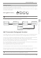
GCU Ports
The following table shows the connections between the GCU channels and the relevant TX channels.
TX Channels
GCU
Channels
Indications
JR Futaba/Hitec
AILE 1 ROLL For roll axis control (left/right). Velocity is zero if disconnected.
ELEV 2 TILT For tilt axis control. Velocity is zero if disconnected.
RUDD 4 PAN For pan axis control. Velocity is zero if disconnected.
AUX2 7 MODE For Working Mode switch and Auto-calibration Function.
2-position switch channel SHUT
For camera shutter control (both taking photos and
recording video are available). Off if disconnected.
2-position switch channel AUX1 For the 360° Panoramic Photograph Function.
2-position switch channel AUX2
When AUX2 is connected to a 2-position switch channel, it
is used as a camera orientation (down or forward) switch
in FPV Mode (Reset). The camera orientation is forward if
disconnected.
Or if you are using a S-Bus receiver, connect the recever
to the AUX2 port.
2- position switch channel
or PPM channel
AUX3
When the AUX3 is connected to a 2-position switch chan-
nel, it is used to toggle video recording.
If you are using a PPM receiver, connect the receiver to the
AUX3 port.
The following table shows the corresponding relationship between the GCU and the S-Bus/PPM channels.
S-Bus/PPM Channels GCU Channels S-Bus/PPM Channels GCU Channels
1 ROLL 5 SHUT
2 TILT 8 AUX1
4 PAN 9 AUX2
7 MODE 6 AUX3
Working Mode /AUX1/AUX2/AUX3 Switch Setup
Working Mode Switch Settings
Whichever 3-position switch you select to use as the Working Mode switch, wire the relevant channel from
the receiver to the MODE port. At each switch position, use end-point ne tuning to set channel AUX2(JR) or
7(Futaba/Hitec) for all three Working Modes:
Working Mode /AUX1/AUX2/AUX3 Switch Setup