Zenmuse Z15-5D III (HD) User Manual 2014.09 V1.
Warning & Disclaimer Do not modify or adjust the Z15-5D III (HD). The Z15-5D III (HD) gimbal has been calibrated specifically for the designated camera and lens before it leaves the factory. Please mount only the designated camera and lens to the Z15-5D III (HD). No adjustments or modifications are needed. Do not add any other component/device (such as filters, lens hood, etc.) to the camera.
Product Profile The Z15-5D III (HD) is a sophisticated gimbal specifically designed for aerial creativity. It has a built-in independent IMU module, special servo drive module, HDMI-HD/AV module, and more. The Z15-5D III (HD) performs well in all modes, including Orientation-locked, Non orientation-locked, and FPV (Reset). Product Profile Working Modes Orientation-locked Non orientation-locked FPV (Reset) Gimbal Direction Gimbal pans with aircraft nose. Gimbal pan and aircraft nose move separately.
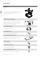
In the Box Gimbal×1 In the Box The Z15-5D III (HD) gimbal includes built-in servo drive modules, an independent IMU module and a HDMI-HD/AV module. Gimbal Control Unit (GCU) ×1 Connect the GCU to your flight control system using the CAN-Bus cable. The GCU will control the gimbal’s pan, roll and tilt movements. Connect the GCU to video downlink for video signal. Lens Retaining Ring ×1 For mounting the camera lens. Mounting Bracket ×4 For mounting the gimbal to the landing gear.
Zenmuse Z15-5D III (HD) User Manual Screw Package ×1 For mounting the gimbal to your aircraft (M2.5*8 cap head screw). 10-Pin to 9-Pin Cable × 2 For connecting the GCU to the gimbal. In the Box 7-Pin Cable × 1 For connecting the GCU to the Lightbridge air system. 8-Pin to 6-Pin Cable × 2 For connecting the GCU to the gimbal. Servo Cable Package × 1 For connecting the GCU and the receiver.
Contents 6 Warning & Disclaimer Manual Tips Legend 2 2 2 Product Profile In the Box Contents Gimbal Description Camera Setup Mount Mounting the Lens Mounting the Camera Mounting the Gimbal to the Landing Gear 3 4 6 7 8 8 8 9 9 Camera Wiring and Shutter Control 360° Panoramic Photograph Function Auto-calibration Function Video Signal Transmission 10 11 A. AV Wireless Video Transmission B. DJI iOSD Mark II and AV Wireless Video Transmission C.
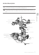
Gimbal Description To avoid motor damage, ensure there is nothing blocking the rotation of the servo drive modules. Clear obstacles or immediately cut off the power if any blockage occurs. The servo drive modules have two motor command input ports and one private encoder port. The HDMI-HD/AV module converts HDMI to HD (or AV) using a cable connected to the camera HDMI port.
Camera Setup Follow the steps below to configure your camera to work with the Z15-5D III (HD). Please read the relevant section for your camera. Canon 5D Mark III Camera Setup / Mount Mode Dial Movie Shooting 1. Set the shooting mode to Shutter-priority AE (Tv) or Manual exposure (M) by turning the Mode Dial. / ) to the Movie shooting position. 2. Turn the Live View shooting/Movie shooting switch ( 3. Press the AF.DRIVE button and select the drive mode as (10-sec.
Zenmuse Z15-5D III (HD) User Manual Mounting the Camera Lens Retaining Ring Screw Mount Camera Mounting Screw 2. Mount the camera onto gimbal as shown above. 3. Adjust the camera and tighten the top camera mounting screw. Then tighten the bottom camera mounting screw and the lens retaining ring screw. Mounting the Gimbal to the Landing Gear The following diagram shows the gimbal mounted on a DJI S1000. You may also mount the gimbal onto different landing gear by referring to this diagram.
Zenmuse Z15-5D III (HD) User Manual 4. Mount the gimbal onto the landing gear with the mounting brackets. Tighten the screws and use thread locker. Ensure the lens is pointing in the same direction as the aircraft nose. Ensure the top and bottom plates of the damping unit stay parallel when mounting. This prevents stretching and distortion. Maintain good overall balance when mounting in order to ensure the center of gravity is balanced on each of the three axis lines.
Zenmuse Z15-5D III (HD) User Manual 3-Positon Switch Shutter Control The Z15-5D III (HD) gimbal can transform a transmitter command into a shutter control signal. Select a 2-position switch/channel to use for remote shutter control. For whichever 2-position switch you select, connect the correct receiver channel to the SHUT port.
Auto-calibration Function The auto-calibration function is new to the Z15-5D III (HD) gimbal. It can help solve vibration problems that may be caused by the gimbal sensor drifting. You can use the auto calibrate function when the following conditions are met: 1. The aircraft is on flat, level ground. Wireless Video Transmission Module to the aircraft IMU. 2. The landing gear is parallel Air Unit 3.
Zenmuse Z15-5D III (HD) User Manual B. DJI iOSD Mark II and AV Wireless Video Transmission Wireless Video Transmission Module Air Unit 14V 5D-HD 52V ROLL TILT GCU PAN MODE Video Signal Port G7 SHUT AUX1 AUX2 AUX3 Power Yellow Video Signal MODE Video Signal Port G7 SHUT AUX1 Make sure toGND connect the wireless video transmission module and the iOSD MarkII cableAUX2 to the GCU AUX3 before powering on. C. DJI Lightbridge Air System 5D-HD GCU ©2014 DJI. All Rights Reserved.
Zenmuse Z15-5D III (HD) User Manual This example is based on a Z15-5D III (HD) gimbal and the A2 flight control system. 1. Connect the Gimbal Port on the Lightbridge Air System to the G7 port on the Z15-5D III (HD) GCU using the supplied HD video power cable (7-pin cable). 2. Connect the DBUS port on the Lightbridge Air System to the DBUS port (X2 port) on the A2 flight control system. Toggle the HD/AV switch to the HD position. 3.
Zenmuse Z15-5D III (HD) User Manual A2/WKM Battery (4S~12S) USB Port PC connection for configuration and firmware upgrades with an USB cable.
Zenmuse Z15-5D III (HD) User Manual GCU Ports The following table shows the connections between the GCU channels and the relevant TX channels. TX Channels JR Futaba/Hitec GCU Channels AILE 1 ROLL ELEV 2 TILT For tilt axis control. Velocity is zero if disconnected. RUDD 4 PAN For pan axis control. Velocity is zero if disconnected. AUX2 7 MODE For Working Mode switch and Auto-calibration Function.
Zenmuse Z15-5D III (HD) User Manual Orientation-locked MODE channel end-point 60%~90% FPV (Reset) back to center Non orientation-locked MODE channel end-point 60%~90% The gimbal will work in Orientation-locked mode if the MODE channel is disconnected. FPV mode is the default startup mode when the MODE channel is connected. The Working Mode from the previous power cycle will be retained if the cable between MODE and the RC receiver is disconnected during operation.
Zenmuse Z15-5D III (HD) User Manual 3-Positon Switch AUX3 Switch Settings The Z15-5D III (HD) supports starting and stopping your camera’s video record function by using a 2-position switch through AUX3. Connect the relevant channel of the receiver to the AUX3 port. Toggle the switch to start/stop recording. 2-Positon Position-1: Start recording Switch Position-2: Stop recording PC Assistant Tuning Installation and Usage 1. Ensure the most recent drivers are installed correctly.
Zenmuse Z15-5D III (HD) User Manual Upgrade You can view the latest firmware version information on this page. Upgrade the firmware by following the steps below: 1. Connect the gimbal to your computer with a Micro-USB cable, and wait until the blue indicator LED in the Assistant software is blinking. 2. Click “Upgrade”. 3. Wait for the download to finish. 4. Click “Upgrade” again and then click “Confirm”. 5. Power cycle the gimbal (turn it off, then on again) after the upgrade is complete.
Zenmuse Z15-5D III (HD) User Manual Pre-Flight Check Pre-Flight Check Ensure the gimbal is properly installed and attached to the landing gear, and that the camera is mounted correctly and securely. Before powering on, spin the gimbal through its complete rotation by hand on each axis to ensure nothing is blocking its movement. Ensure all cables are connected correctly, without any plugged in backwards or into the wrong ports.
Zenmuse Z15-5D III (HD) User Manual Flight Test 1. 2. 3. 4. 5. If the gimbal does not match the diagram after initialization, please refer to the Troubleshooting section in Appendix. ©2014 DJI. All Rights Reserved. 21 Pre-Flight Check Ensure the batteries are fully charged for your TX, GCU, and all of the other devices on your aircraft. Make sure all connections and wiring are in good condition. Switch on the TX. Adjust the camera to a level position on the roll axis of the gimbal.
Appendix Attention For safety reasons, please pay careful attention to all of the following items: 1. To avoid motor damage, ensure nothing blocks the servo drive module’s total range of movement. 2. Before powering on, spin the gimbal through its complete rotation by hand on each axis to ensure nothing is blocking the mechanical movement of the gimbal. 3. Be sure to mount the side of servo drive module 1 with the ports facing towards the aircraft tail. 4. The gimbal’s center of gravity has been preset.
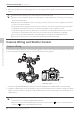
Zenmuse Z15-5D III (HD) User Manual 1. Prepare one 14-channel TX/RC receiver for the aircraft and gimbal control. Above is an example of the wiring configuration. 2. Setup the Aileron, Elevator, Throttle, and Rudder channels on your TX for aircraft roll, elevator, throttle, and rudder control. Also, connect the TX’s AUX2 for aircraft control modes (Please refer to your Flight Control System’s user manual). 3. Choose three 3-position switches to use for the gimbal ROLL, TILT, and PAN rotation control.
Zenmuse Z15-5D III (HD) User Manual Port Descriptions GCU ROLL For roll axis control TILT For tilt axis control PAN For pan axis control MODE For Working Mode switch SHUT For camera shutter control and auto-calibration function AUX1 For the 360° panoramic photograph function AUX2 For Gimbal Orientation (down or forward) switch in FPV Mode ; S-Bus Receiver AUX3 For the video recording control ; PPM Receiver G7 XT60 1.
Zenmuse Z15-5D III (HD) User Manual Troubleshooting NO. The Cause What to Do 1 The gimbal keeps drifting after initialization. (1) The TX trims are too high. (2) The GCU and Flight Control System have been disconnected. (3) The gimbal direction is not pointing in the same direction as the aircraft’s nose. (1) Adjust the TX trims. (2) Connect the GCU and Flight Control System. (3) Ensure the gimbal direction is pointing in the same direction as the aircraft’s nose.
Zenmuse Z15-5D III (HD) User Manual Specifications General Built-In Functions Three Working Modes Orientation-locked control Non orientation-locked control FPV mode (Reset) Built-in independent IMU module DJI gimbal special servos drive module HDMI-HD/AV module Wireless video transmission supported Camera shutter control supported Wide range voltage input supported S-Bus/PPM Receiver supported 360° panoramic photograph function Auto-calibration function Peripheral Supported Camera CANON EOS 5D MARK III
User manual is subject to change without prior notice. You may visit DJI offical website to obtain the latest version of user manual. http://www.dji.com/product/zenmuse-z15-5d-iii-hd/download © 2014 DJI. All Rights Reserved.