
Technical data


1592022750 Quick reference guide IC 200CX Rel. 1.1 25/05/2009
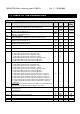
CF 45
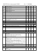
OUT 3 configuration
0= Not enabled
1= 0..10V signal for compressor 1 inverter controlled
2= 0..10V signal for compressor 2 inverter controlled
3= 0..10V signal for auxiliary output 1
4= 0..10V signal for auxiliary output 1
5= 0..10V signal for geothermal function
6= 0..10V signal for condenser fan circuit 1
7= 0..10V signal for condenser fan circuit 2
8= PWM signal for condenser fan circuit 1
9= PWM signal for condenser fan circuit 2
o1 .. c26 signal to drive external relay
0
o 1
9
c26
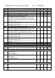
CF 46
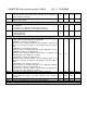
OUT 4 configuration
0= Not enabled
1= 0..10V signal for compressor 1 inverter controlled
2= 0..10V signal for compressor 2 inverter controlled
3= 0..10V signal for auxiliary output 1
4= 0..10V signal for auxiliary output 1
5= 0..10V signal for geothermal function
6= 0..10V signal for condenser fan circuit 1
7= 0..10V signal for condenser fan circuit 2
8= PWM signal for condenser fan circuit 1
9= PWM signal for condenser fan circuit 2
o1 .. c26 signal to drive external relay
0
o 1
9
c26
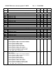
Remote keyboard
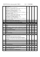
CF 47
Remote keyboard 1 configuration
0= Not enabled
1= with NTC temperature sensor on board
2= without NTC temperature sensor on board
0 2
CF 48
Remote keyboard 2 configuration
0= Not enabled
1= with NTC temperature sensor on board
2= without NTC temperature sensor on board
0 2
CF 49
Offset of the probe mounted on the remote keyboard 1 -12.0
-21
12.0
21
°C
°F
Dec
int
CF 50
Offset of probe mounted on the remote keyboard 2 -12.0
-21
12.0
21
°C
°F
Dec
int
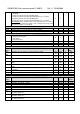
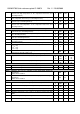
Icon function
CF 51
Icon and keys for chiller and heat pump
0= chiller / heat pump
1= chiller / heat pump
0 1
Chiller / heat pump selection mode
CF 52
Chiller / heat pump selection
0= selection by keys on the keyboard
1= selection by digital input
2= selection by probe
0 2
Unit of measurement
CF 53
Unit of measurement
0= °C / °BAR
1= °F / °psi
0 1
Voltage frequency