
Technical data


Ichill 200CX EVO rev 1.1 14/11/2013
Pag. 61 of 151
Regulation of the heaters in heat pump
The Par. Ar07 selects the probe/s control for the anti-freeze alarm and the relay outputs configured as anti-
freeze / support / boiler heaters for the circuits 1 and 2 in heat pump mode.
Par. Ar07 = 0: the function is disabled
Par. Ar07 = 1: function enabled; the regulation probe is evaporator water inlet.
Par. Ar07 = 2: function enabled; the regulation probe are evaporator water outlet circuit 1 and evaporator
water outlet circuit 2.
ATTENTION:
It is not possible to control the heaters of the circuit #1 with the probe of the circuit #2 and
viceversa.
Par. Ar07 = 3: function enabled; the regulation probe are evaporator water outlet circuit 1, evaporator water
outlet circuit 2 or evaporator common probe.
Par. Ar07 = 4: function enabled; the regulation probe is outside temperature.
ANTI-FREEZE HEATERS, INTEGRATION HEATING, BOILER HEATERS DURING THE DEFROST
CYCLE
The Ar05 parameter allows to choose the operation mode of the heaters during the defrost:
Par. Ar05 = 0: The heaters are activated according the regulation request.
Par. Ar05 = 1: The heaters are activated only by the regulation request and are always on during the defrost.
The heaters are switched on when the 4-way valve change from heat-pump to chiller and switched off only
after the dripping time and the compressors restart.
Condenser Anti-freeze heaters regulation
The parameter Ar08 allows to select the heaters probe control in chiller and heat pump mode.
Par. Ar08 = 0: the function is disabled.
Par. Ar08 = 1: function enabled; the regulation probe is condenser water inlet.
Par. Ar08 = 2: function enabled; the regulation probe are condenser water inlet circuit 1, condenser water
inlet circuit 2 and condenser water common inlet.
ATTENTION:
It is not possible to control the heaters of the circuit #1 with the probe of the circuit #2 and
viceversa.
Par. Ar08 = 3: function enabled; the regulation probe are evaporator water outlet circuit 1, evaporator water
outlet circuit 2
Par. Ar08 = 4: function enabled; the regulation probe are evaporator water outlet circuit 1, evaporator water
outlet circuit 2 and condenser common outlet.
ATTENTION
When the outputs are configured as heaters circuit #1 and 2 they are both controlled by the NTC probe of
the common condenser outlet.
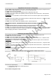
Graph of the anti-freeze- integration heating - boiler heater relays
Boiler function
The function is enabled when:
One probe is configured as outside temperature.
Parameter Ar11 > 0.
Ar11=1 Boiler in integration mode