
Technical data


Ichill 200CX EVO rev 1.1 14/11/2013
Pag. 131 of 151
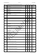
Ar 12 External air temperaure setpoint for boiler heaters (on) -50.0
-58
110.0
230
°C
°F
Dec
int
Ar 13 Temperature differential for boiler heaters (off) 0.1
0
25.0
45
°C
°F
Dec
int
Ar 14 Time delay before turning the boiler on 0 250 Min
Ar 15 Setpoint for boiler heaters (on) in chiller -50.0
-58
110.0
230
°C
°F
Dec
int
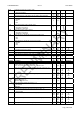
Ar 16 Proportional band for boiler heaters in chiller 0.1
0
25.0
45
°C
°F
Dec
int
Ar 17 Setpoint for boiler heaters (on) in HP -50.0
-58
110.0
230
°C
°F
Dec
int
Ar 18 Proportional band for boiler heaters in HP 0.1
0
25.0
45
°C
°F
Dec
int
Ar 19 External air setpoint to stop the compressor as integration function -50.0
-58
110.0
230
°C
°F
Dec
int
Ar 20 External air differential to stop the compressor as integration function 0.1
0
25.0
45
°C
°F
Dec
int
Ar21 Termoregulation probe anti freeze alarm in chiller mode
0= Not enabled
1= Evaporator inlet
2= Evaporator outlet 1 and 2
3= Evaporator outlet 1 and 2 and common outlet
4= External temperature
0 4
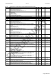
Ar22 Termoregulation probe anti freeze alarm in heat pump mode
0= Not enabled
1= Evaporator inlet
2= Evaporator outlet 1 and 2
3= Evaporator outlet 1 and 2 and common outlet
4= External temperature
0 4
Ar23 Termoregulation probe anti freeze alarm water condenser
0= not enabled.
1= Condenser common water inlet probe.
2= Condenser common water inlet and condenser inlet 1 / 2 probe.
3= Condenser water outlet 1 / 2 probe.
4= Condenser water outlet 1 / 2 and common outlet
5= External temperature
0 5
Ar24 Water pump / antifreeze alarm in OFF/ stand-by
0= Aways in OFF
1= ON only with thermoregulation control
0 1
Ar25 Termoregulation probe water pump in antifreeze mode
0= Not enabled
1= Evaporator inlet
2= Evaporator outlet 1 and 2
3= Evaporator outlet 1 and 2 and common outlet
4= External temperature
0 4
Ar26 Set point starting water pump in antifreeze alarm
-50.0
-58
110.0
230
°C
°F
Dec
int
Ar27 Differential starting water pump in antifreeze alarm
0.1
0
25.0
45
°C
°F
Dec
int
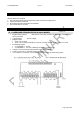
Parameter Description min max M. u. Resolution
dF 1 Defrost configuration:
0= Not enabled
1= Start and stop for temperature / pressure
2= Start depends on probe selected by par. dF24 and stop for time duration
(dF05)
3= Start depends on probe selected by par. dF24 and stop for external
contact
4= Defrost only with condenser fan
5= Start from digital input and stop on probe selected by par. dF24
0 5
dF 2 Temperature or pressure of the defrost start-up -50.0
-58
0.0
0
110.0
230
50.0
725
°C
°F
bar
psi
Dec
int
Dec
Int
dF 3 Temperature or pressure of the defrost stop -50.0
-58
0.0
0
110.0
230
50.0
725
°C
°F
bar
psi
Dec
int
Dec
Int
dF 4 Minimum defrost duration. 0 250 Sec
dF 5 Maximum defrost duration. 0 250 Min
dF 6 Time delay between the defrost of two circuits 0 250 Min
dF 7 OFF compressor delay before the defrost 0 250 Sec
dF 8 OFF compressor delay after the defrost 0 250 Sec
dF 9 Defrost interval time of the same circuit 1 99 Min
dF 10 Temperature setpoint for combined defrost of the 1st circuit after parameter
DF10 counting.
-50.0
-58
110.0
230
°C
°F
Dec
int