
Technical data


Ichill 200CX EVO rev 1.1 14/11/2013
Pag. 130 of 151
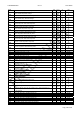
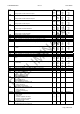
FA 22 Over ride CUT- OFF in Heat pump. To set a temperature/pressure differential
to keep the minimum fan speed.
0.1
0
0.1
1
25.0
45
14.0
203
°C
°F
Bar
Psi
Dec
int
Dec
int
FA 23 Night speed in Heat pump. To set the maximum fan speed percentage value
(30..100%), it is related to the fan power supply.
0 100 %
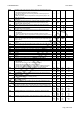
FA 24 Hot start setpoint -50.0
-58
110.0
230
°C
°F
Dec
int
FA 25 Hot start differential 0.1
0
25.0
45
°C
°F
Dec
int
FA 26 ON/OFF regulation FA01 = 2/3
SETpoint step n° 3
-50.0
-58
0.0
0
110.0
230
50.0
725
°C
°F
Bar
Psi
Dec
int
Dec
int
FA 27 ON/OFF regulation FA01 = 2/3
SETpoint step n° 4
-50.0
-58
0.0
0
110.0
230
50.0
725
°C
°F
Bar
Psi
Dec
int
Dec
int
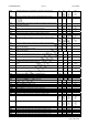
FA 28 ON/OFF regulation FA01 = 2/3
SETpoint step n° 3
-50.0
-58
0.0
0
110.0
230
50.0
725
°C
°F
Bar
Psi
Dec
int
Dec
int
FA 29 ON/OFF regulation FA01 = 2/3
SETpoint step n° 4
-50.0
-58
0.0
0
110.0
230
50.0
725
°C
°F
Bar
Psi
Dec
int
Dec
int
FA 30 Pre ventilation in Heat Pump
(only if FA01 = 4 )
0 250 Sec Sec
FA 31 Post ventilation in Heat Pump 0 250 Sec 10Sec
FA 32 Outside temperature to enable post ventilation in Heat Pump -50.0
-58
110.0
230
°C
°F
Dec
int
FA 33 Condenser fan speed during post ventilation 0 100
%
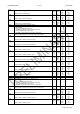
Parameter Description min max M. u. Resolution
Ar 1 Anti-freeze heaters/integration heating setpoint for air/air unit in Chiller mode.
To set a temperature value, below this value the anti-freeze relay is activated.
-50.0
-58
110.0
230
°C
°F
Dec
int
Ar 2 Regulation band for antifreeze in Chiller mode. 0.1
0
25.0
45
°C
°F
Dec
Int
Ar 3 Set Anti-freeze heaters/integration heating setpoint for air/air unit in HP mode.
To set a temperature value, below this value the anti-freeze relay is activated.
-50.0
-58
110.0
230
°C
°F
Dec
int
Ar 4 Regulation band for antifreeze in HP mode. 0.1
0
25.0
45
°C
°F
Dec
int
Ar 5 Antifreeze heaters / integration heating in defrost
0= ON only with thermoregulation control
1= ON with thermoregulation and during the defrosting cycle
0 1
Ar 6 Antifreeze probe to manage heaters / support heaters in Chiller mode.
0= Not enabled
1= Evaporator inlet
2= Evaporator outlet 1 and 2
3= Evaporator outlet 1 and 2 and common outlet
4= External temperature
0 4
Ar 7 Antifreeze probe to manage heaters / support heaters in HP mode.
0= Not enabled
1= Evaporator inlet.
2= Evaporator outlet 1 and 2.
3= Evaporator outlet 1 and 2 and common outlet
4= External temperature
0 4
Ar 8 Thermoregulation probe for anti-freeze / condenser heaters.
0= not enabled.
1= Condenser common water inlet probe.
2= Condenser common water inlet and condenser inlet 1 / 2 probe.
3= Condenser water outlet 1 / 2 probe.
4= Condenser water outlet 1 / 2 and common outlet
5= External temperature
0 5
Ar 9 Anti-freeze heaters or condenser/evaporator water pump control with unit in
remote OFF or stand-by mode:
0= Control not enable
1=Controlled by anti-freeze thermoregulation.
0 1
Ar 10 Anti-freeze heaters control for condenser/evaporator faulty probe:
0= Anti-freeze heaters OFF
1= Anti-freeze heaters ON
0 1
Ar 11 Boiler function
0=Not enabled
1=Enabled for integration heating
2= Enabled for heating
0 2