
Technical data


Ichill 200CX EVO rev 1.1 14/11/2013
Pag. 125 of 151
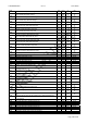
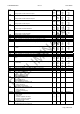
CO 47 Unloading Differential. From temperature / pressure in HP mode (See
unloading function).
0.1
0
0.1
1
25.0
45
14.0
203
°C
°F
Bar
Psi
Dec
int
Dec
int
CO 48 Maximum unloading duration time from temperature/pressure control. 1 250 Min
CO 49 Number of steps for circuit with active unloading
1= 1st step
2= 2nd step
3= 3rd step
1 3
CO 50 Minimum ON time of the capacity step after the unloading function start (only
for capacity compressor)
0 250 Sec
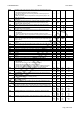
CO 51 Setpoint of the solenoid valve (on) of the liquid injection 0
32
150
302
°C
°F
Dec / int
int
CO 52 Setpoint of the solenoid valve (off) of the liquid injection 0.1
0
25.0
45
°C
°F
Dec
int
CO 53 Maximum time of work in neutral zone without insert resource 0 250 Min 10 Min
CO 54 Maximum time of work in neutral zone without rotation resource 0 999 Hr 1Hr
CO 55 Set point unloading compressor from low evaporator water temperature
-50.0
-58
110.0
230
°C
°F
Dec
int
CO 56 Differential unloading compressor from low evaporator water temperature
0.1
0
0.1
1
25.0
45
14.0
203
°C
°F
Bar
Psi
Dec
int
Dec
int
CO 57 Maximum unloading duration time from low evaporator water temperature
0 250 Min
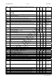
CO 58 maximum time pump-down in stopped
CO58 = 0 Not enabled
0 250 Sec
CO 59 maximum time pump-down in started
CO59 = 0 Not enabled
0 250 Sec
CO 60 Maximum time start up compressor inverter controlled
0 250 sec
CO 61 Minimum value proportional output from start up compressor
0 100 %
CO 62 Minimum time capacity variation from start up compressor inverter controlled
0 250 sec
CO 63 Minimum percentage continuative of work of the compressor inverter
controlled before to start counting CO64 time
0 100 %
CO 64 Maximum time continuative of work of the compressor with percentage less of
CO63
0 250 Min 10 Min
CO 65 Time of forcing the compressor inverter controlled to the maximum power
0 250 sec sec
CO 66 Maximum time continuative of work of the compressor inverter controlled
0 999 Hr 1Hr
CO 67 Minimum value of the compressor 1 inverter controlled
1 CO68 %
CO 68 Maximum value of the compressor 1 inverter controlled CO67 100 %
CO 69 Minimum value of the compressor 2 inverter controlled 1 CO70 %
CO 70 Maximum value of the compressor 2 inverter controlled CO69 100 %
CO 71 Minimum time capacity variation compressor inverter controlled 1 250 sec
CO 72 Maximum operating time of a single compressor
0 250 Min
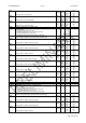
CO 73 Sanitary water pump hour counter 0 999 10 Hr 10 Hr
CO 74 Solar panel water pump hour counter 0 999 10 Hr 10 Hr
CO 75 Forced time to reverse the 4 way valve when the compressor is switched off 0 250 sec
CO 76 Maximum number of compressors to use in Chiller 1 15
CO 77 Maximum number of compressors to use in Heat pump 1 15
CO 78 Maximum number of compressors to use in Sanitary water 1 15
CO 79 Maximum % output of the inverter compressor in Chiller 1 100 %
CO 80 Maximum % output of the inverter compressor in Heat pump 1 100 %
CO 81 Maximum % output of the inverter compressor in Sanitary water 1 100 %
CO 82 Outside temperature to reduce inverter compressor speed in Heat pump -50.0
-58
0.0
0
110.0
230
50.0
725
°C
°F
Bar
Psi
Dec
int
Dec
int
CO 83 Hysteresis temperature to reduce inverter compressor speed in Heat pump 0.1
0
0.1
1
25.0
45
14.0
203
°C
°F
Bar
Psi
Dec
int
Dec
int
CO 84 Compressor speed if outside temperature > CO82 0 100 %
CO 85 Evaporator water pump OFF time if the set point is reached 0 250 10 min
CO 86 Evaporator water pump OFF time if the machine is STD-BY or OFF 0 250 10 Ore
CO 87 Evaporator water pump ON time 0 250 Sec 10sec
CO 88 Condenser water pump OFF time if the set point is reached 0 250 10 min
CO 89 Condenser water pump OFF time if the machine is STD-BY or OFF 0 250 10 Ore
CO 90 Condenser water pump ON time 0 250 Sec 10sec