
Technical data


Ichill 200CX EVO rev 1.1 14/11/2013
Pag. 123 of 151
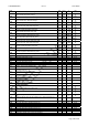
ES 29 Friday: Sanitary water 2nd set point activation 0 7
ES 30 Saturday: Sanitary water 2nd set point activation 0 7
ES 31 Sunday: Sanitary water 2 set point activation 0 7
ES 32 2nd set point Sanitary water offset -30.0
-54
30.0
54
°C
°F
Dec
int
ES 33 2nd set point Sanitary water differential 0.1
0
25.0
45
°C
°F
Dec
int
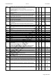
Parameter Description min max M. u. Resolution
Cr1 Type of functioning compressor rack
0= Not enabled
1= regulation by ST09 probe
2 = regolation by pressure probe (Evaporator pressure probe)
0 2
Cr2 Set point compressor suction probe
Cr03 Cr04
Bar
Psi
Dec
int
Cr3 Minimum set point compressor suction probe
0 Cr02
Bar
Psi
Dec
int
Cr4 Maximum set point compressor suction probe
Cr02
50
725
Bar
Psi
Dec
int
Cr5 Regulation band suction probe
0.1
1
14.0
203
Bar
Psi
Dec
int
Cr6 Set energy saving compressor rack
0.0
0
14.0
203
Bar
psi
Dec
int
Cr7 Differential energy savingcompressor rack
0.1
1
14.0
203
Bar
Psi
Dec
int
Cr8 Number of compressors enabled in case of failure probe
0 ÷ 6
0 6
Cr9 Number od ventilation step in case of failure probe
0 ÷ 4
0 4
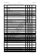
Parameter Description min max M. u. Resolution
CO 1 Minimum compressor ON time after the start-up. 0 250 10 sec 10 sec
CO 2 Minimum compressor OFF time after the switching off. 0 250 10 sec 10 sec
CO 3 ON delay time between two compressors or compressor and valve. During
this time the led of the next resource is blinking.
1 250 Sec
CO 4 OFF delay time between two compressors or compressor and valve. During
this time the led of the next resource is blinking.
0 250 Sec
CO 5 Output time delay after the main power supply start-up to the unit.
All the loads are delayed in case of frequently power failures.
0 250 10 Sec 10 sec
CO 6 Functioning (see Capacity Control)
0= With on/off steps
1= Continuous with steps and direct action
2= Continuous with steps and reverse action
3= Continuous with steps and direct total action
0 3
CO 7 Start-up with minimum compressor power / automatic start-unloading valve
0 = Only at the compressor start-up (Minimum power automatic start-
unloading valve off)
1= At the compressor start-up and during the termoregulation (Minimum
power / automatic start-unloading valve off)
2 = Only at the screw compressor start-up (Minimum power automatic start-
unloading valve off)
3= At the compressor start-up and during the termoregulation (Minimum
power / Unloading valve ON with compressor off)
0 3
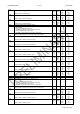
CO 8 Relay ON time of the Solenoid valve Intermittent for screw compressor, with 0
the function is not enabled.
0 250 Sec
CO 9 Relay OFF time of the Solenoid valve Intermittent for screw compressor 0 250 Sec
CO 10 Kind of compressor start-up
0= Direct ( vedi avviamento compressors )
1= Part - winding
0 1
CO 11 If CO10= 1 part - winding start-up time. To change the time delay between the
two contactors of the two compressor circuits.
0 100
Dec. di
Sec
0.1 sec
CO 12 Not used
CO 13 By-pass gas valve start-up time / automatic start-unloading valve (capacity
step control)
0 250 sec
CO 14 Compressor rotation (See compressor rotation)
0 = Sequential
1 = Compressors rotation based on time running hours
2 = Compressors rotation based on number of starts-up
0 2
CO 15 Circuit balancing (See Circuit balancing)
0= Circuit saturation
1= Circuit balancing
0 1