
Technical data


Ichill 200CX EVO rev 1.1 14/11/2013
Pag. 118 of 151
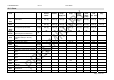
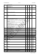
CF 25 Pressure value at 20mA or 5 Vdc of the PB3 transducer -1.0
-14
50.0
725
Bar
psi
Dec
int
CF 26 Pressure value at 4mA or 0.5 Vdc of the PB4 transducer -1.0
-14
50.0
725
Bar
psi
Dec
int
CF 27 Pressure value at 20mA or 5 Vdc of the PB4 transducer -1.0
-14
50.0
725
Bar
psi
Dec
int
CF 28 Not used 0 0
CF 29 Not used 0 0
CF 30 Configuration of ID1 0 -o1 c75
CF 31 Configuration of ID2 0 -o1 c75
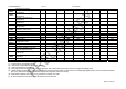
CF 32 Configuration of ID3
0 -o1
c75
CF 33 Configuration of ID4 0 -o1 c75
CF 34 Configuration of ID5 0 -o1 c75
CF 35 Configuration of ID6 0 -o1 c75
CF 36 Configuration of ID7 0 -o1 c75
CF 37 Configuration of ID8 0 -o1 c75
CF 38 Configuration of ID9 0 -o1 c75
CF 39 Configuration of ID10 0 -o1 c75
CF 40 Configuration of ID11 0 -o1 c75
CF 41 Configuration of RL1 0 -o1 c74
CF 42 Configuration of RL2 0 -o1 c74
CF 43 Configuration of RL3 0 -o1 c74
CF 44 Configuration of RL4 0 -o1 c74
CF 45 Configuration of RL5 0 -o1 c74
CF 46 Configuration of RL6 0 -o1 c74
CF 47 Configuration of RL7 0 -o1 c74
CF 48 Configuration of RL8 0 -o1 c74
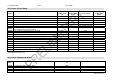
CF 49 Not used
CF 50 Proportional output OUT 1
0= not configured
1= modulation evaporator water pump 0÷10V
2= Free cooling modulating output 0÷10V
3= not used
4= auxiliary output AUX1 0÷10V
5= auxiliary output AUX2 0÷10V
6= inverter compressor 1 0÷10V
7= inverter compressor 2 0÷10V
8= modulating condenser fan circuit 1 0÷10V
9= modulating condenser fan circuit 2 0÷10V
o1..c50 ON / OFF with the same meaning of relè configuration
0
o 1
9
c50
CF 51 Proportional output OUT 2
0= not configured
1= modulation evaporator water pump 0÷10V
2= Free cooling modulating output 0÷10V
3= not used
4= auxiliary output AUX1 0÷10V
5= auxiliary output AUX2 0÷10V
6= inverter compressor 1 0÷10V
7= inverter compressor 2 0÷10V
8= modulating condenser fan circuit 1 0÷10V
9= modulating condenser fan circuit 2 0÷10V
o1..c50 ON / OFF with the same meaning of relè configuration
0
o 1
9
c50
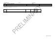
CF 52 Proportional output OUT 3
0= not configured
1= modulation evaporator water pump 0÷10V
2= Free cooling modulating output 0÷10V
3= not used
4= auxiliary output AUX1 0÷10V
5= auxiliary output AUX2 0÷10V
6= inverter compressor 1 0÷10V
7= inverter compressor 2 0÷10V
8= modulating condenser fan circuit 1 0÷10V
9= modulating condenser fan circuit 2 0÷10V
10= modulating condenser fan circuit 1 PWM
11= modulating condenser fan circuit 2 PWM
o1..c50 ON / OFF output with the same meaning of relè
0
o 1
11
c50