
Technical data


Ichill 200CX EVO rev 1.1 14/11/2013
Pag. 116 of 151
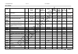
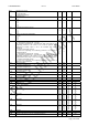
49. TABLE OF PARAMETERS
Parameter Description min max M. u. Resolution
ST 1 Chiller Setpoint ST02 ST03 °C/°F dec/int
ST 2 Chiller minimum Setpoint
-50.0
-58
ST01
°C
°F
Dec
int
ST 3 Chiller maximum Setpoint
ST01
110
230
°C
°F
Dec
int
ST 4 Heat pump setpoint ST05 ST06 °C/°F dec/int
ST 5 Heat pump minimum Setpoint -50.0
-58
ST04
°C
°F
Dec
int
ST 6 Heat pump maximum Setpoint
ST04
110
230
°C
°F
Dec
int
ST 7 Regulation band in chiller mode 0.1
0
25.0
45
°C
°F
Dec
int
ST 8 Regulation band in chiller heat pump 0.1
0
25.0
45
°C
°F
Dec
int
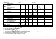
ST 9 Regulation probe selection in chiller
0= Temperature probe NTC for evaporator inlet
1= Temperature probe NTC for evaporator outlet 1
2= Temperature probe NTC for evaporator outlet 2
3= Temperature probe NTC for common evaporator outlet
4= Temperature NTC probe from remote panel 1
5= Temperature NTC probe from remote panel 2
0
5
ST 10 Regulation probe selection in heat pump
0= Temperature probe NTC for evaporator inlet
1= Temperature probe NTC for evaporator outlet 1
2= Temperature probe NTC for evaporator outlet 2
3= Temperature probe NTC for common evaporator outlet
4= Temperature NTC probe from remote panel 1
5= Temperature NTC probe from remote panel 2
6= Temperature probe for water common inlet of the condenser
7= Temperature probe for water inlet of the circuit # 1 condenser
8= Temperature probe for water inlet of the circuit # 2 condenser
9= Temperature probe for water outlet of the circuit # 1 condenser
10= Temperature probe for water outlet of the circuit # 2 condenser
11= Temperature probe for water common otlet of the condenser
0 11
ST 11 Type of thermoregulation
0= Proportional
1= Neutral zone
0 1
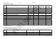
Visualizzazione display
Parameter Description min max M. u. Resolution
dP 1 Default read-out of the top display 0 16
dP 2 Default read-out of the bottom display 0 20
dP 3 Default display read-out configuration top / bottom
0= Configurable
1= Top display: Evaporator IN, Bottom display: Evaporator OUT
2= Top display: Condenser IN, Bottom display: Condenser OUT
3=Top display: temperature/Condensing pressure, Bottom Display:
evaporating pressure
0 3
dP 4 Top display default read-out of the remote terminal_1
0= the read-out depends on the paremeters dP01 – dP02 – dP03
1= the read-out shows the NTC probe of the remote panel.
0 1
dP 5 Top display default read-out of the remote terminal_2
0= the read-out depends on the paremeters dP01 – dP02 – dP03
1= the read-out shows the NTC probe of the remote panel.
0 1
dP 6 Visograph: firs probe visualized 0 35
dP 7 Visograph: second probe visualized 0 35
dP 8 Visograph: third probe visualized 0 35
dP 9 Visograph: fourth probe visualized 0 35
dP 10 Visualization in STD-BY
0= "STD-BY"
1= same visualization of dP1 and dP2
2= “OFF”
0 2
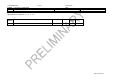
Parameter Description min max M. u. Resolution
Unità
CF 1 Type of unit
0= Air / air Chiller
1= Air / water Chiller
2= Water / water Chiller
0 2