
Install Instructions
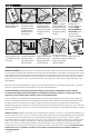


5. Ensure that sensor
angle to ground does not
exceed 30 degrees, adjust
if necessary.
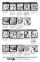
Installation Instructions for Auxiliary Drain Line
2. Glue threaded bush
to 90° elbow tting and
install threaded nipple.
1. Disconnect power to
HVAC unit at Main panel
before installation.
6. Wire the sensor per
the attached instructions
and diagram. Can be
connected with either
Red or Yellow wires.
9. Place supplied warning
sticker on air handler unit.
7. Test sensor function by
lifting oat while the HVAC
unit is running to ensure
unit stops when the oat
ascends to trip point.
OFF
3. Thread the 90° elbow
assembly into auxiliary
drain output port and
tighten into position to
ensure leak-free t.
4. Firmly press CS-2
sensor into the 90° elbow
tting. DO NOT GLUE
THE SENSOR TO THE
ASSEMBLY. Sensor can
be removed for inspection
and cleaning.
8. Test the connections for
leaks. Plug pan or line and ll
pan with water to verify water
height at sensor activation
and proper installation.
Red
White
Green
Yellow
Furnace / AC
From ThermostatTo Switch
DiversiTech Corporation
6650 Sugarloaf Parkway
Duluth, GA 30097 USA
For more information visit:
www.diversitech.com
CS-2