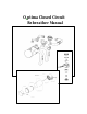
O2ptima Closed Circuit Rebreather Manual
O2ptima Manual –User Guide – Rev 1.2 Page 2 of 26 __________________________________________________________________ CONFIDENTIAL This document is for use by, O2PTIMA owners only, and is the property of Lamartek, Inc. dba Dive Rite Dissemination of the information contained herein to outside parties is expressly prohibited. Text, photographs, and figures copyright ©2005 by Asseer & Associates Inc. HammerHead Manual is copyright Joseph A Radomski used under permission. 175 NW Washington St.
O2ptima Manual –User Guide – Rev 1.2 Page 3 of 26 __________________________________________________________________ Table of Contents 1. Preface ....................................................................................... 4 2. User Guide................................................................................. 6 2.1. 2.2. 2.3. 2.4. 2.5. 2.6. 2.7. 2.8. Breathing Loop Assembly ..................................................................................... 6 Canister ..............
O2ptima Manual –User Guide – Rev 1.2 Page 4 of 26 __________________________________________________________________ 1. Preface Congratulations on your decision to purchase what is quite possibly the most sophisticated self-contained underwater breathing apparatus ever developed. Two years of intensive research, experimentation, and testing by a team of dedicated individuals have culminated in the creation of O2PTIMA, a electronically controlled, mixed-gas, closed-circuit rebreather system.
O2ptima Manual –User Guide – Rev 1.2 Page 5 of 26 __________________________________________________________________ Please take the time to fully understand all of the O2PTIMA’s system components before entrusting your life to them. This manual explains the O2PTIMA in great detail, but only you, the user, can control the outcome of your dives. Learn what the O2PTIMA can do to expand your capabilities underwater. Practice standard operational protocols until they become intuitive.
O2ptima Manual –User Guide – Rev 1.2 Page 6 of 26 __________________________________________________________________ 2. User Guide The O2ptima CCR was designed to ensure assembly and disassembly of the unit is straightforward and simple. WARNING: THE FOLLOWING INSTRUCTIONS ARE ASSEMBLY INSTRUCTIONS ONLY. FURTHER TRAINING IS REQUIRED PRIOR TO USING THE UNIT. INITIAL ASSEMBLY IS TO BE COMPLETED UNDER THE SUPERVISION OF THE CERTIFYING O2PTIMA INSTRUCTOR. 2.1.
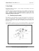
O2ptima Manual –User Guide – Rev 1.2 Page 7 of 26 __________________________________________________________________ 2.2. Canister Canister assembly should be performed in a clean dry and well lit area.
O2ptima Manual –User Guide – Rev 1.2 Page 8 of 26 __________________________________________________________________ Scrubber cartridge o-ring 1. Screw in the three O2 cells into the Sensor Holder Disk. No cell should be placed in location 4 unless a stand alone computer is using this as an input. Remove the oring from the O2 cells if applicable. Sensor Holder Disk 2.
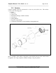
O2ptima Manual –User Guide – Rev 1.2 Page 9 of 26 __________________________________________________________________ 3. Plug-in the wiring harness into the banana jack block inside the head. Ensure that the colors match and that the ground for each cell is plugged into its appropriate spot. Banana Jack Plugs 4. Secure the O2 disk into the head with provided screw. Do not over tighten.
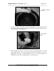
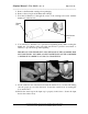
O2ptima Manual –User Guide – Rev 1.2 Page 10 of 26 __________________________________________________________________ 5. Remove the Extendair cartridge from packaging. 6. Remove the red cap from the Extendair cartridge. 7. Feed the O2 Premix rod through the center of the cartridge and secure with the thumb nut on the far side. Thumb Nut O2 Premix rod 8. You will have to hold the rod to prevent from spinning freely while securing the thumb nut.
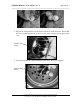
O2ptima Manual –User Guide – Rev 1.2 Page 11 of 26 __________________________________________________________________ 11. Insert hose connectors into the head and input cap. The red connector must be screwed into the head (left hand thread). The black connector is screwed into the input cap. 2.3. Inhalation Side The inhalation side comes over the divers left shoulder. It is comprised of 2 hoses (with red connectors), 1 Auto-Diluent valve and 1 counter lung with appropriate fittings.
O2ptima Manual –User Guide – Rev 1.2 Page 12 of 26 __________________________________________________________________ 2. Attach the short breathing hose with red connectors to the ADV and the other end to the assembled canister. This hose has left handed threads and does not have a specific flow direction. 3. Attach the diluent supply to the ADV. This connection should only be finger tight. Ensure that the manual shut-off is accessible when wearing the unit. 4.
O2ptima Manual –User Guide – Rev 1.2 Page 13 of 26 __________________________________________________________________ 2.4. Exhalation Side The exhalation side comes over the divers’ right shoulder. It is comprised of 2 hoses (black connectors), 1 T-Piece and 1 counter lung with appropriate fittings. All the exhalation side threads are right handed threads and are black in color. 1. Attach the T-Piece to the exhalation lung. The T-Piece does not have a specific orientation. 2.
O2ptima Manual –User Guide – Rev 1.2 Page 14 of 26 __________________________________________________________________ 2.5. DSV (Diver Supply Valve) The DSV does not typically need any assembly or disassembly. The DSV does contain two mushroom valves to provide flow direction. Both mushroom valves are removable for maintenance and cleaning (see the Maintenance section). 2.6. DIVA The DIVA (Display Integrated Vibration Alarm) is designed as a H.U.D. – Heads Up Display.
O2ptima Manual –User Guide – Rev 1.2 Page 15 of 26 __________________________________________________________________ 2.8. Electronics The O2ptima electronics are supplied by Juergensen Marine. Please see the HammerHead manual for specific user functionality. The O2ptima electronics are shipped out of the facility with all lock out codes erased from the handset. This renders the electronics inoperable until the proper code is keyed into each of the handsets.
O2ptima Manual –User Guide – Rev 1.2 Page 16 of 26 __________________________________________________________________ 3. Maintenance To ensure many years of trouble free diving, it is critical that proper maintenance be performed on the O2ptima. Lack of maintenance can affect the proper functionality of the unit and will void any warranty. 3.1.
O2ptima Manual –User Guide – Rev 1.2 Page 17 of 26 __________________________________________________________________ completely remove O2 cells and disk by disconnecting the wiring harness. Spray disinfectant on a cloth and clean the bottom of the head. WARNING: YOU WILL NEED TO RE-CALIBRATE O2 CELLS ONCE THE HARNESS HAS BEEN DISCONNECTED. 3.2. Storage If storing the O2ptima CCR for any extended period of time, store the unit in a clean and dry environment.
O2ptima Manual –User Guide – Rev 1.2 Page 18 of 26 __________________________________________________________________ IMPORTANT!!! When re-assembling the DSV, extreme care should be taken to ensure the valves have been put in the proper orientation for air loop flow. The long hose with red connector should be on the inhalation side and the long hose with black connector should be on the exhalation side. A mushroom valve check should perform after reassembly. 3.5.
O2ptima Manual –User Guide – Rev 1.2 Page 19 of 26 __________________________________________________________________ every 12 months or at any time excessive corrosion is seen on either end of the wiring harness connectors. 3.8. Solenoid Valve The solenoid valve selected for the O2ptima CCR should provide years of trouble free diving.
O2ptima Manual –User Guide – Rev 1.2 Page 20 of 26 __________________________________________________________________ 3.10. Scrubber Medium The O2ptima CCR has been designed to use Extendair cartridges manufactured by Micropore. The Extendair absorbent use the same chemistry as granular absorbents but they are formed into sheets that are rolled into easy to use cartridges. The Extendair cartridge has been extensively tested in order to determine maximum duration of the scrubber material.
O2ptima Manual –User Guide – Rev 1.2 Page 21 of 26 __________________________________________________________________ 4. Unit Assembly Section 4 of the manual covers the overall assembly of the unit. Some of these steps are required to be done every dive while others are only done when first assembling the unit or when a complete down of the unit is required. The first assembly of the unit should be done with a certified Optima instructor. 1.
O2ptima Manual –User Guide – Rev 1.2 Page 22 of 26 __________________________________________________________________ 2. Run the required hoses through the provided ports (see previous picture for front view). 3. Secure wing and Transpac or Tranplate to internal support bar using provide hardware. Bolts are to secure to the threaded holes on the support bar. Feed ports for diluent and O2 hoses Internal Support Bar Threaded holes on the internal support bar to secure wing and harness 4.
O2ptima Manual –User Guide – Rev 1.2 Page 23 of 26 __________________________________________________________________ Valve tabs 5. Insert canister and screw on the O2 inject hose. The O2 hose should only be finger tight. DO NOT OVERTIGHTEN O2 HOSE. Canister tie down strap O2 injection hose connection (hand tight only).
O2ptima Manual –User Guide – Rev 1.2 Page 24 of 26 __________________________________________________________________ 6. Install back lid 7. Install Breathing lungs. The upper harness has to loop under the lungs. Clip the top of the lungs with the provided clips.
O2ptima Manual –User Guide – Rev 1.2 Page 25 of 26 __________________________________________________________________ 8. Install remainder of the breathing loop as per directions from Section 2.
O2ptima Manual –User Guide – Rev 1.2 Page 26 of 26 __________________________________________________________________ Troubleshooting Issue / Problem Positive and/or negative pressure tests can not be preformed • • • • Oxygen cell calibration • • • Handsets are in dive mode at the surface • • Handsets reset to start up screen • • • Solution Ensure all fittings are secured. Ensure DSV is fully closed. Ensure over pressurization valve is fully closed.
Optima HammerHead Electronics Instruction Manual The Hammerhead, also has handsets called the primary and secondary, but each has different purpose and functions. The primary is responsible for maintaining the selected set-point, displaying the measured PO2 for the three main oxygen sensors, time, depth and decompression information. The secondary is a backup display for the main oxygen sensors, and controller for the DIVA Heads-Up display.
Normal display Primary Handset Set-Point #1 Set-Point #2 Changed Version 4.5 Version 4.
Normal display Secondary Handset Set-Point #1 Set-Point #2 User Defined Values Set-Point #3 User Entry Set-Point #4 Set-Point #5 OPT DEFINE SET POINT 1 2 3 BACKLIGHT TIMER 2 – 30 Seconds AUTO SHUTDN RATE 2 to 30 minutes 4 5 CALIBRATE O2 MV DISPLAY DIAGNOSTICS SET DISPLAY MODE ABOUT Erase Flash Test Flash Test Watchdog Enter SN Initialize Volts Display USER SETPOINT 1.
System Overview Before being able to dive the unit, it is necessary to understand a few basic conventions used by the controllers, calibrate the oxygen sensors and set diver preferences. Initially out of the factory, some common set-points are defined, all gas mixes are programmed to AIR, and sea level is set at approximately 1840 ft above sea level. If the data becomes corrupted or unusable, it can be easily reset to factory defaults. The primary handset can operate using Imperial or Metric units of depth.
The other unique feature pertaining to set-point maintenance is the algorithm used to hold the selected set-point. Each manufacture comes up with their own unique formula to determine when oxygen is injected; the user generally has no control over this function.
Juergensen’s Threat Matrix Diver forgets to turn on unit: ¾ Answer: Wet Switches Wet Switches Fail: ¾ Answer: Pressure Transducer will activate unit at 1m pressure Diver sets unit to Open Circuit, but is still breathing the loop. ¾ Answer: Solenoid Override at 0.19 PO2 Diver sets unit to Manual Control, but forgets to add O2: ¾ Answer: Solenoid Override at 0.
ALARMS START Primary READ PO2 Green Flashing LED FLASHING BACKLIGHT Red Flashing LED PO2 >= 1.8 AVERAGE PO2 PO2 <=.19 FLASHING BACKLIGHT FIRE SOLENOID SYSTEM OK START Secondary READ PO2 DIVA VIBRATING FLASHING BACKLIGHT DIVA VIBRATING FLASHING BACKLIGHT PO2 >= 1.8 Check Status PO2 <=.
Handset Display Details The Primary handset has several informational screens that vary depending on whether the unit is in surface mode, no deco obligation, or deco required conditions. This is the surface mode screen; the top line consists of the surface interval, selected set-point or open circuit indicator, maximum depth of previous dive, and 1:38 OC 008 000 finally dive time. The second line is the current PO2 0.73 0.73 0.71 reading for the three oxygen sensors.
line. This should help insure the diver doesn’t try and use a nitrogen mix with same oxygen percentage as a helium based gas Set-Point Operation One of the main features of the hammerhead is the ability for the diver to select a new set-point based on a user programmed set of five choices. The hammerhead comes pre-programmed with set-points of 0.4, 0.7, 1.0, 1.2, and 1.4. Regardless of the current operating set-point pressing the left button will cycle through the set-point choices in sequence.
measurements for each sensor. Any individual sensor out of range will be voted out. The voting logic used in both the primary and secondary handsets is identical. Any sensor that is 15% out of range from the average of the remaining two sensors will be voted out. The second, third and fourth screenshots show sensor one voted out. The second screenshot shows system status of , this is indicated if any sensor is voted out or average po2 is at least 15% from selected set-point.
OC NEXT SELECT OC Open Circuit OPT NEXT SELECT The next option allows the diver to put the handset in either open circuit or close circuit mode. In open circuit mode, solenoid control is disabled, unless the PO2 falls to 0.19Ata. This function serves two purposes. The first allows the diver to bail onto open circuit and still have decompression obligations calculated. The second is to use the handset as a stand-alone dive computer.
The next option is setting the level of conservatism for the decompression model. The original software has eleven levels of conservatism, setting “1” Conservatism being the least conservative and setting “11” being the NEXT SELECT most conservative. The GF-low and GF-high limits are decreased equally with increasing level of conservatism forcing deeper stop depths and lower allowed limits of inert gas loading. Starting with version 4.
sites. Gradient factors is a method used to control the shape of the decompression profile. in a consistent manner. There are two parameters GF-Low and GF-High. The first parameter determines where the initial stop begins. The second parameter determines the maximal allowing tissue loading upon surfacing. These two points determine the slope used to modify the “M-values” during the ascent. For each given depth the “M-value” is lowered based on the computed GF for that depth.
decompression obligation. NO conservatism setting or decompression plan can guarantee ZERO risk of decompression sickness! The next option allows the entry of the custom gradient discussed in the previous section. The first value entered is the GF-High, followed by the GF-Low setting. Custom Gradient Gf Hi = [100] Custom Gradient NEXT SELECT Custom Gradient Gf Lo = [ 95] This is necessary to allow setting the upper limit for the GF-Low setting 5% below the GF-High value.
unit from remaining on. Let the unit sit for at least FIVE minutes. This allows time for any inert gas remaining in the loop to mix. Top with oxygen if any volume from the loop is lost and go to the “MV display” screen again. If the sensor values have decreased, the flush was incomplete so flush again and repeat.
Imperial—Metric NEXT SELECT The Imperial – Metric setting selects system of units that will be used for displaying depth on the current hardware revision; future hardware upgrades will add temperature measurement. The current selected units will be displayed, pressing the LEFT button will toggle and RIGHT will select. The solenoid firing function sets the set-point control algorithm.
better setting. In shallow water, a low value will hold a stable set-point with little or no overshooting, but as depth increases, an overshoot is probable. An error setting of 5% works well over a wide range of depths with acceptable results for most divers. The general rule of thumb is as depth increases; the allowed error should be increased to prevent overshoot. Dive mode does not locked out this option; this allows the value to changed at any time.
O2ptima Pre Dive Check List Name: _________________________________ Date of dive: ____/____/____ Rig ID: ______________ Sensor S/N: (1) _____________ (2) ______________ (3) _______________ BATTERY DATA: DATE INSTALLED PRIMARY SECONDARY Table 1 Dive start time: _________ Stop time: _________ Initials Note: Initial only when task has been performed. ____ 1. Inspect all parts for dirt, deterioration, damage, and lubrication during assembly. ____ 2. Charge O2 and diluent cylinders.
O2ptima Post Dive Check List Date of -dive: ____/____/____ Dive start time: _________ Stop time: _________ Initials Note: Initial only when task has been performed. ____ 1. Rinse CCR in fresh water. ____ 2. Record cylinder pressures O2, ______PSI/BAR Diluent: ______ PSI/BAR ____ 3. Secure O2 and diluent cylinders and bleed down system via bypass valves. ____ 4. Disconnect all L.P. hoses, ADV, and displays from various assemblies. ____ 5. Remove DSV assembly from counterlungs . Rinse and disinfect. ____ 6.