O2ptima FX CCR Owner’s Manual Version 1, Rev 4 a product of Dive Rite
II Dive Rite O2ptima FX CCR Owner’s Manual Dive Rite Optima Rebreather ©2007,2009 Dive Rite All Rights Reserved. USA Copyright Registration: Copyright protection claimed includes all forms and matters of copyrightable material and information now allowed by statutory or judicial law or hereinafter granted, including without limitation all charts, photos, illustrations, displays, graphics, etc. Certain Graphics and text have been reproduced, with permission.
O 2 ptima FX Owner’s Manual III Table of Contents Introduction. . . . . . . . . . . . . . . . . . . . . . . . . . . . . . . . . . . . . . . . . . . . . . . . . . . . . . . . . . . . . . V Chapter 1 Common Terms and Diving Systems.. . . . . . . . . . . . . . . . . . . . . . . . . . . . Ch. 1 Pg. 1 Glossary (Ch. 1 Pg. 1); Common Acronyms (Ch. 1 Pg. 3); Scuba System Overview (Ch. 1 Pg. 4); Open-Circuit Systems (Ch. 1 Pg. 4); Semi-closed Circuit Rebreathers (Ch. 1 Pg. 5); Closed-Circuit Systems (Ch. 1 Pg.
IV Dive Rite SECONDARY Handset Options and Programming. . . . . . . . . . . . . . . . . . . . . . . . Ch. 3 Pg. 13 STACK TIME OPT (Ch. 3 Pg. 13); VIEW STACK TIME (Ch. 3 Pg. 13); SET STACK TIME (Ch. 3 Pg. 13); RESET STACK TIME (Ch. 3 Pg. 14); TEST STACK TIME (Ch. 3 Pg. 14); DECOMPRESS MODE (Ch. 3 Pg. 14); DISPLAY OPTIONS (Ch. 3 Pg. 15); SET DIVA MODE (Ch. 3 Pg. 15); User Set Point: (Ch. 3 Pg. 16); PPO2 mode Flash Protocol: (Ch. 3 Pg. 16) Chapter 4 Dive Planning and Procedures.. . . . . . . . . . . . . . .
O 2 ptima FX Owner’s Manual V Introduction The O2ptima is a fully closed mixed gas capable closed circuit rebreather. Unlike other products both past and present, this design represents the collaboration of several manufacturers within the diving and safety industries. Each company was able to bring their strengths to this product, increasing safety and reliability. While many designs have needed to evolve over the years, the O2ptima, at its release represented some of the best technology available.
O 2 ptima FX Owner’s Manual Ch. 1 Pg. 1 Chapter 1 Common Terms and Diving Systems Objective The purpose of this chapter is to briefly outline the various diving systems in use, to discuss the advantages and disadvantages of each, and to define common diving terms and acronyms. Glossary The following is a list of terms that are frequently used by divers and may be used throughout this manual.
Ch. 1 Pg. 2 Dive Rite Left Hand Valve This is the valve that would be operated by the diver using his/her left hand based on a set twin cylinders with a manifold. The knob is on the opposite side when compared to a “normal” valve. This designation is NOT universal with all valve manufacturers, consult the appropriate product catalog when ordering valves. Over Pressure Valve This valve is used to automatically vent excess gas from the loop during ascent.
O 2 ptima FX Owner’s Manual Ch. 1 Pg. 3 packed loose granules or a disposable cartridge. There are two main types, Radial and Axial. Semi-Closed Rebreather SCR A type of rebreather where the breathing loop is isolated from the environment. During normal operation some percentage of the gas is periodically or continually vented and replaced with fresh gas (usually Nitrox). The most common SCR is one with a constant preset gas flow but SCRs keyed to the diver’s respiratory rate do exist.
Ch. 1 Pg. 4 SC SCR WOB Dive Rite Semi-Closed Semi Closed Rebreather Work of Breathing Scuba System Overview The Open-Circuit Scuba system is the configuration that is usually associated with scuba diving and the configuration used by the average recreational diver. This chapter will introduce the semi-closed and closed-circuit rebreather designs or more simply, SCR and CCR.
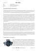
O 2 ptima FX Owner’s Manual Ch. 1 Pg. 5 None of the exhaled gas is reused, so the breathing circuit is said to be “open”, hence the term “Open-Circuit Scuba”. The original open-circuit scuba regulator was a two-hose style regulator and was based on previous designs of closed-circuit Oxygen systems. Inhaled gas comes over the right shoulder entering the first of two flexible breathing hoses, past a non-return or "one-way" valve and into the mouthpiece.
Ch. 1 Pg. 6 Dive Rite a demand valve with fresh oxygen rich gas. Since there is venting of used or excess gas while at a constant depth, the descriptive name of “semi-closed-circuit” is appropriate. The amount and quantity of exhaled gas will depend on the flow rate of the replacement gas source, whether its fixed or tied to the diver’s respiration rate.
O 2 ptima FX Owner’s Manual Ch. 1 Pg. 7 The earliest designs required the diver to chose the target PO 2 or FO 2 during setup but current systems allow the diver to vary the gas mixture being breathed during the dive. These CCR systems employ an electronically-controlled gas mixing system that blends the gas from two separate cylinders.
O 2 ptima FX Owner’s Manual Ch. 2 Pg. 1 Chapter 2 Component Description Mouthpiece The DSV on the O2ptima, is a low profile, low volume design to minimize dead-air spaces and resistance in the water. The DSV contains no O-Rings and depends on good lubrication and proper machining for a water-tight seal. This design has an advantage in that there can be no sudden gas loss due to a failed O-Ring but under normal conditions MAY leak gas slightly while in air.
Ch. 2 Pg. 2 Dive Rite are RED in color. The hose fittings on the exhalation side of the loop are right-handed fittings, tighten clockwise, and are BLACK in color. Counter-lungs The O2ptima uses two detachable over-the-shoulder (OTS) counter-lungs. This configuration offers the best breathing characteristics in all possible positions, allows an individual diver to adjust the counter-lung for optimal positioning, and allows for easy cleaning and care.
O 2 ptima FX Owner’s Manual Ch. 2 Pg. 3 and have the hoses removable, others have the T-Pieces removable but have the hoses permanently connected, but the O2ptima is different in that the hoses are removable and the TPiece is removable from the counter-lung. This design allows the easiest cleaning, maintenance and testing of the various components.
Ch. 2 Pg. 4 Dive Rite Loop Over-Pressure Valve The O2ptima rebreather uses a special valve as a loop overpressure relief. This valve will normally be operated in the open position (turned fully counter-clockwise). Divers with a large tidal volume may be required to close the OPV slightly to maintain the proper loop volume. During the ascent, the gas in the loop will expand, increasing buoyancy and increasing the breathing effort slightly.
Ch. 2 Pg. 5 O 2 ptima FX Owner’s Manual Oxygen First Stage and Connections Oxygen Side Assembly as supplied by the factory The oxygen first stage is the Dive Rite Model RG1208. The IP (intermediate pressure) for the oxygen side must be set to 90 psi (6.2 Bar). This is lower than the normal factory standard setting for the RG1208 used for most applications. Pressures above 90 psi (6.2 Bar) will cause higher battery drain on the primary handset, and may prevent the Solenoid from properly firing.
Ch. 2 Pg. 6 Dive Rite Diluent First Stage and Connections Diluent Side Assembly as supplied by the factory The diluent first stage is the Dive Rite Model RG1208. The IP (intermediate pressure) should be set to factory standards of 140 psi (9.7 Bar). The normal configuration from the factory is a LP feed connected to a 3 port manifold, a LP inflator for the manual diluent addition valve, a first stage over-pressure valve (OPV), and a submersible pressure gauge.
O 2 ptima FX Owner’s Manual Ch. 2 Pg. 7 Optima Solenoid WARNING DISASSEMBLING THE SOLENOID WILL CAUSE DAMAGE TO THE SOLENOID AND WILL VOID ANY IMPLIED OR STATED WARRANTIES. The Dive Rite O2ptima has an oxygen safe solenoid in the head of the unit which is controlled by the primary Juergensen handset to inject oxygen into the breathing loop. The solenoid can be identified by tracing the yellow power wire from the sensor block in the head to the black cap 1 covering the magnetic housing of the solenoid.
Ch. 2 Pg. 8 Dive Rite Mounting Frame The mounting frame used on the O2ptima allows the use of most cylinders up to a length of 15 inches (38cm) and a diameter of 5.5 inches (14cm). The total overall length including the valve can be approximately 19 inches (48 cm). The O2ptima is available with several different cylinder options. The frame is made from a sturdy light weight ABS plastic, with a stainless steel reinforcement bar running down the center.
O 2 ptima FX Owner’s Manual Ch. 3 Pg. 1 Chapter 3 HammerHead Electronics Introduction This chapter is a basic overview of the electronics used on the HammerHead CCR. This chapter is meant as a quick introduction rather than a detailed manual documenting all the features and their uses. A separate document “HammerHead Electronics User Manual” that is meant as a complete documention is available from Juergensen Marine and several sources on the internet.
Ch. 3 Pg. 2 Dive Rite Activation PINS: Primary: Serial Number: __________ User: _________ Helium: _________ Secondary: Serial Number: __________ User: _________ Deco: _________ The primary handset can operate using Imperial or Metric units of depth and temperature but the PO2 on both handsets is ALWAYS displayed in units of ATA not Bar. This should be of particular interest because several other CCRs and dive computers use Bar as base unit.
O 2 ptima FX Owner’s Manual Ch. 3 Pg. 3 HANDSET DISPLAY DETAILS PRIMARY: The Primary handset has several informational screens that vary depending on whether the unit is in surface or dive mode, and if decompression stops are required. This is the surface mode screen; the top line consists of the surface interval, selected set-point or open circuit indicator, maximum depth of previous dive, and finally dive time. The second line is the current PO 2 reading for each of the three oxygen sensors.
Ch. 3 Pg. 4 Dive Rite SECONDARY: The Secondary handset has three possible display options (“Classic” - Classic, “D/Timer” - Depth/Timer, and “D/TandS” - Depth/Timer/Stack Timer). Classic Mode This mode displays system status, warnings and PO 2 on a single screen. All warnings and alarms are based on the deviation from the target set-point. The secondary must be set to the desired set-point in the same manner as the primary.
Ch. 3 Pg. 5 O 2 ptima FX Owner’s Manual Depth/Timer Mode This mode cycles between THREE different screens. The PO 2 for all cells is displayed on the second line of all screens. The first screen is identical to classic mode and is the main status screen. The second screen displays current depth, Temperature and maximum depth. The third screen displays the current depth and the total dive time in the format hours:minutes:seconds. 0.8 1.1* 0.86 0.7 0.81 25.6 68F > 28.6 1.00 1.00 1.00 24.
Ch. 3 Pg. 6 Dive Rite If there are any required decompression stops, the next screen will have the standard status line, but the second line now displays the oxygen percentage of the diluent, deepest stop depth and stop time followed by the total ascent time. The sample screen shows the deepest stop at 20fsw for two minutes and a TTS of 12 minutes. This screen is displayed for approximately 2 seconds. 1.0 21% 2@ 20 1.
Ch. 3 Pg. 7 O 2 ptima FX Owner’s Manual Handset Operational Overview The options available in the primary handset are grouped into two main “menus”. The first grouping contains the functions most likely to be used during a dive, while the second grouping under the options menu ”OPT” is used to gain access to additional functions including handset configuration. For safety reasons several functions in the second grouping are unavailable while in dive mode.
Ch. 3 Pg. 8 OC NEXT Dive Rite SELECT The next option allows the diver to put the handset in either open circuit or close circuit mode. In open circuit mode, solenoid control is disabled, OC unless the PO2 falls to 0.19Ata. This function allows the diver to bail Open Circuit onto open circuit and still have decompression obligations calculated.
O 2 ptima FX Owner’s Manual Ch. 3 Pg. 9 MILLIVOLT DISPLAY This option displays the millivolt output for each of the three sensors. While in this mode the backlight remains illuminated and does not timeout. Pressing either button exits the test. This option Sen1 Sen2 Sen3 should be used to record the output of each sensor while in AIR and 100% Oxygen. A log with this information can aid in tracking the cells decay over time. The mV display is also used to diagnose cell problems.
Ch. 3 Pg. 10 Dive Rite Recommended Calibration Sequence: (1) Connect ALL regulators, leave DILUENT Valve off. On systems equipped with an ADV and cut-off valve, make sure the valve is in the off position. (2) Turn on Oxygen and Activate handsets. Make sure that the solenoid fires for several seconds to flush Oxygen through the solenoid. This is easily accomplished by setting the set-point to 1.0 then setting it to a 0.4 once the purge is completed.
O 2 ptima FX Owner’s Manual Ch. 3 Pg. 11 independent! The calibrate option is disabled while in dive mode to prevent a possible accident by the wet switches sensing water or depth sensor detecting a depth. The HammerHead holds a very stable calibration; it is not necessary to constantly recalibrate the handsets. The sensors should be verified to be within a few percent of expected values by performing a quick loop flush with oxygen and/or exposing the sensors to AIR prior to each dive.
Ch. 3 Pg. 12 Dive Rite PASSWORD MANAGER Passwrd Manager NEXT SELECT Enter UsrEN PW NEXT SELECT [1234] NEXT SELECT Enter HeEN PW NEXT SELECT [1234] NEXT SELECT This option allows the user to enable/disable Helium gas usage and to erase all PINs to disable the unit entirely. PINs are supplied to certified users through a student’s instructor. Upon the sale of the rebreather/electronics to another party, the handsets should be disabled by clearing all the PINs.
O 2 ptima FX Owner’s Manual Ch. 3 Pg. 13 SECONDARY Handset Options and Programming The secondary handset has many of the same options as the primary handset. The notable differences are the lack of functions supporting the deco computer and set-point control options. The secondary has FOUR additional options, “Stack Time Opt” , “Decompress Mode“, “Display Options” and “Set DIVA Mode”. STACK TIME OPT The stack timer is convenience reminder, and should not be counted on as a life support feature.
Ch. 3 Pg. 14 Dive Rite RESET STACK TIME The “Reset Stack Time” option resets the current stack time to the limit as set in the “Set Stack Time” option. Choosing this option (with the RIGHT button) will prompt the diver to confirm with a LEFT button press. Reset Stack Time NEXT SELECT TEST STACK TIME The purpose of the “Test Stack Time” option is to allow the diver to become familiar with the alarms generated on the secondary display, the flash protocol on the DIVA coupled with the vibrating of the DIVA.
O 2 ptima FX Owner’s Manual Ch. 3 Pg. 15 DISPLAY OPTIONS The “Display Options” explanation is detailed in the section on display details earlier in the manual. The Three supported display modes are “Classic” (Classic), “D/Timer” (Depth plus Bottom Timer), “D/TandS” (Depth, Bottom Timer plus Stack Timer).
O 2 ptima FX Owner’s Manual Ch. 4 Pg. 1 DIVA DISPLAY MODES User Set Point: The secondary uses the 3 available colors within the DIVA to signal alarm conditions. The flash rate and color is dependent on the error percentage from the user selected set-point. (1) Set-point error is less than 15%; the secondary blinks the DIVA GREEN LED every 8 seconds. (2) Set-point error is 15% to 24% or a sensor voted out; the secondary blinks the DIVA ORANGE LED every 5 seconds.
O 2 ptima FX Owner’s Manual Ch. 5 Pg. 1 Chapter 4 Dive Planning and Procedures Oxygen Oxygen is the gas that sustains life, but the oxygen dosage must fall within a specific range in order to sustain life. Too little leads to unconsciousness and eventually death, and too much causes respiratory and central nervous system issues. The term used to describe the amount of Oxygen present in the breathing mixture is “partial pressure dosage” or PO 2 .
Ch. 5 Pg. 2 Dive Rite The following chart lists the limits as established by NOAA. NOAA O 2 EXPOSURE LIMITS Oxygen Partial Pressure (PO 2 ) ( ata ) Maximum Single Exposure Maximum Daily Exposure (min) (hrs) (min) (hrs) 1.6 4 5 0.75 150 2.5 1.5 120 2.0 180 3.0 1.4 150 2.5 180 3.0 1.3 180 3.0 210 3.5 1.2 210 3.5 240 4.0 1.1 240 4.0 270 4.5 1.0 300 5.0 300 5.0 0.9 360 6.0 360 6.0 0.8 450 7.5 450 7.5 0.7 570 9.5 570 9.5 0.6 720 12.0 720 12.
Ch. 5 Pg. 3 O 2 ptima FX Owner’s Manual Lets examine a dive for 20 minutes at 100fsw and 30 minutes at 60fsw using a setpoint of 1.3ata. (20 minutes + 30 minutes) X 100 / 180 minutes = % CNS 50 minutes X 0.56 % / minute = 28% CNS Residual Oxygen Toxicity (CNS%) While on the surface, your Percentage of Oxygen Toxicity is reduced in a similar fashion to the way Nitrogen out-gases from the body.
Ch. 5 Pg. 4 Dive Rite CO2 Scrubber Duration The O2ptima CO 2 scrubber duration was conducted using the ExtendAir EP CO 2 absorbent cartridge and scrubber canister designed by Micropore. The Dive Rite recommended duration for sport diving depths is maximum of 240 liters of CO 2 produced. To avoid CO 2 production tracking the duration can be adjusted down to three hours in warm water and two hours in cold water. CO 2 production can be approximated y tracking oxygen usage.
O 2 ptima FX Owner’s Manual Ch. 5 Pg. 5 Decompression / No Decompression Dive Planning The O2ptima features a built in dive computer capable of tracking gas loading on a constant PO 2 profile. This does not negate the need to pre-plan the dive nor does it negate the recommendation that some form of backup planning/tracking being employed. Alternate planning/tracking is essential should the tissue loading in the HammerHead become lost or corrupted.
Ch. 5 Pg. 6 Dive Rite Important Cautionary Notes DO: DO: DO: DO: DO: DO: DO: DO: DO: DO: DO: DO: DO: DO: DO DO DO DO DO DO DO NOT: NOT: NOT: NOT: NOT: NOT: NOT: DO DO DO DO NOT: NOT: NOT: NOT: Know your PO 2 at all times! Always open Oxygen and Decompression gas valves very slowly as a prevention against Oxygen fires! Understand all topics presented in this manual Always dive within manufacturer and certification limits. The pre-dive checks prior to each dive. Use diving quality gasses.
Ch. 6 Pg. 1 O 2 ptima FX Owner’s Manual Chapter 5 Component Assembly and Checklists The O2ptima FX has been designed for easy assembly and disassembly. All the components of a completely disassembled unit (less cylinders) fit into the main body (mounting frame plus protective cover) of the rebreather. The Optima FX is shipped from the factory in this configuration and is ideal for long term storage and for protection during travel.
Ch. 6 Pg. 2 Dive Rite The hose for the bailout regulator should now be connected to the manifold. Loosen one of the spare 3/8 port plugs using an 4mm Allen Key and install LP hose. If the wing is to be supplied by the onboard diluent supply, remove the remaining 3/8 port plug and install the LP inflator hose supplied with the wing. The hoses and submersible pressure gauges should now be routed through the cutout in the mounting frame.
O 2 ptima FX Owner’s Manual Ch. 6 Pg. 3 A common problem with many rebreathers is corrosion of the sensor wires. This usually requires the user to ship the unit back to the factory for repair. The O2ptima has taken a modular approach, and replacing the wiring only takes minutes. Carrying a spare harness in the save a dive kit is highly recommended. All sensor connections on the O2ptima are color coded, simply match up the colors.
Ch. 6 Pg. 4 Dive Rite Inspect the o-ring on the end-cap and lubricate if necessary. Locate the water trap, inspect the o-ring for debris and damage. Lubricate the end-cap o-ring surface and press the water trap into place. The orings from the end-cap and water trap should line up next to each other when the water trap is properly installed. Canister Assembly The ease in assembling of the canister is a feature that sets the O2ptima FX apart from other CCRs and is big step in improving diver safety.
O 2 ptima FX Owner’s Manual Ch. 6 Pg. 5 Re-inspect o-rings on end-cap and on the water trap for debris and damage. Verify that the water trap is properly installed into the endcap. Lubricate the canister o-ring surface. Place the end-cap assembly onto the open end of the center tube and rotate until the cap slips into place. Rotate the end cap clockwise until the arrow on the end-cap lines up with the locked indication on the center tube.
Ch. 6 Pg. 6 Dive Rite DIVA The DIVA ships from the factory as an assembled unit. The DIVA needs to be mounted to the DSV. The O2ptima DSV has TWO locations for the diver. The diva can be positioned so that it can be viewed by either the diver’s right or left eye. To install line up the screw hole on the DIVA mount and use the thumb screw supplied with the DSV to secure. A hood is shipped with the O2ptima to improve the visibility in bright conditions.
O 2 ptima FX Owner’s Manual Ch. 6 Pg. 7 Automatic Diluent addition Valve ADV Component Breakdown The ADV comes fully assembled from the factory and is installed by the diver onto the inhalation counter-lung. The screw on fitting is RED signifying the inhalation side of the loop. Examine the TWO orings on the counter-lung fitting for debris and proper lubrication.
Ch. 6 Pg. 8 Dive Rite Removing the ADV from the counter-lung is the reverse of connecting it. The ADV ring should be loosened a few turns at a time and then gently lifting the ADV away from the fitting. Repeat as necessary. ADV Adjustment To adjust the cracking effort on the Optima ADV, the swivel cap must be removed to access the adjustable orifice by using a 5/32" Allen wrench. Next, insert a 3/16" Allen wrench through the swivel and into the adjustable orifice.
O 2 ptima FX Owner’s Manual Ch. 6 Pg. 9 Attaching Counter-lungs and Hoses Once the canister is assembled, the ADV and T-pieces are properly attached to the counter-lungs and the functionality of the DSV has been tested, the rest of the loop can be assembled. The counter-lungs should first be secured to the top of the case by the fastex buckles . The inhalation counter-lung on the diver’s left and the exhalation counter-lung on the diver’s right. The fastex buckles will only accept the proper counter-lung.
Ch. 6 Pg. 10 Dive Rite The final step is to connect the DSV hose assembly. Inspect the o-rings on the connectors for debris and proper lubrication. Connect the RED fitting to the DSV and the Black fitting to the TPiece. These fittings use a fine thread and care should be taken to avoid cross threading the fitting. If the connectors does not engage DO NOT FORCE IT.
Ch. 6 Pg.
Ch. 6 Pg. 12 Dive Rite Complete Pre-Dive Checklist (Continued) _____ 33. Verify voltage in Air is 8mV-13mV, Record Sensor voltages PRIMARY S1____ S2_____S3_____ SECONDARY S1____ S2_____S3_____ Additional Monitor (if equipped) S4_____ _____ 34. Check accumulated service time on CO 2 absorbent: (hrs:min) _____:_____ _____ 35. Is remaining time sufficient for planned dive YES / NO (circle answer) _____ 36. Replace Micropore CO 2 Cartridge when remaining time is insufficient. _____ 37.
Ch. 6 Pg.
Ch. 6 Pg.
O 2 ptima FX Owner’s Manual Ch. 6 Pg. 15 Page intentionally left blank.
O 2 ptima FX Owner’s Manual APP1 METRIC - IMPERIAL CONVERSIONS PRESSURE 1 msw = 1/10 bar 1 msw = 3.2568 fsw 1 ata = 1.01325 bar 1 ata = 1013.25 millibars 1 ata = 760 mm Hg 1 ata = 14.6959 psi 1 ata = 33 fsw 33fsw = 10.1326 msw 1 bar = 14.5037 psi 1 bar = 0.98692 ata 1 bar = 10 msw 1 kg/cm 2 = 14.223 psi DISTANCE 1 meter = 3.28 feet 1 foot = .3048 meter VOLUME 1,000 liters = 1 cubic meter 1 cu. ft. = 28.3168 liters 1 cubic inch = 0.016387064 liter 1 cubic inch = 16.