GLOBE IP1839EN- rev. 2012-07-31 EN Installation and maintenance manual for automations for sectional overhead doors and spring balanced up-and-over doors. (Original instructions) DITEC S.p.A. Via Mons. Banfi, 3 - 21042 Caronno Pertusella (VA) - ITALY Tel. +39 02 963911 - Fax +39 02 9650314 www.ditec.it - ditec@ditecva.
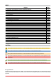
INDEX Subject 1. General safety precautions 2. Declaration of incorporation of partly completed machinery Page 2.1 Machinery Directive 3. Technical data 3.1 Operating instructions 3.2 Dimensions 4. 5. 6. 7. 8. 9. 10. 11. 12. 13. 14. 15. 16. 17. 18. 19. 20. 21. 22. 23.
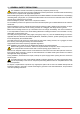
1. GENERAL SAFETY PRECAUTIONS This installation manual is intended for professionally competent personnel only. Installation, electrical connections and adjustments must be performed in accordance with Good Working Methods and in compliance with applicable regulations. Before installing the product, carefully read the instructions. Bad installation could be hazardous. The packaging materials (plastic, polystyrene, etc.
2. DECLARATION OF INCORPORATION OF PARTLY COMPLETED MACHINERY (Directive 2006/42/EC, Annex II-B) The manufacturer DITEC S.p.A. with headquarters in Via Mons. Banfi, 3 - 21042 Caronno Pertusella (VA) ITALY declares that the automation for sectional doors type GLOBE: has been constructed to be installed on a manual gate to construct a machine pursuant to the Directive 2006/42/EC.
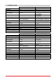
3.
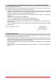
3.1 Operating instructions Service class: 3 (minimum 10÷5 years of working life with 30÷60 cycles per day). Applications: FREQUENT (for multi-family entrances or small condominiums with frequent vehicle or pedestrian access). Performance characteristics are to be understood as referring to the recommended weight (approx. 2/3 of maximum permissible weight). When used with the maximum permissible weight a reduction in the above mentioned performance can be expected.
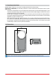
4. STANDARD INSTALLATION 8 RG5 ² .5 mm + 2x1 1.5 mm² ² x 2 mm 4x0.5 .5 mm² 4x0 A 2 1 3 8 4 6 6 7 5 Ref.
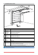
5. MAIN COMPONENTS 500 30 7 10 4 20 2 1 3 5 6 Ref.
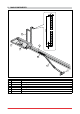
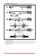
6. Assembling belt and chain 1 A B C 2 D 3A E F A E F 3B E F A E F - Attach the belt or chain [A] to the transmission [B] and slide [C]. - Assemble the belt stop [D]. - Fasten the two ends of the belt [A] to the release pin [E] through the couplings [F] in the direction of the pin, as shown in the figure. - Fasten the two ends of the chain [A] to the release pin [E] through the couplings [F] in the direction of the pin, as shown in the figure.
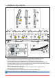
7. Assembling the automation D C C C B B 1 2 1066 370 1066 205 B 3 400 205 370 C A 1066 400 A D B E 205 370 F G D H E I F J - Insert the guide [B] into the non-bevelled side of the coupling [C] until it reaches the stop. - Insert the guide [D] into the bevelled side of the coupling [C] until it reaches the stop. - Insert the guide [D] into the non-bevelled side of the coupling [E] until it reaches the stop.
8. Tensioning belt and chain C B 1 A 2 B C A 1÷2 - Assemble the transmission unit as indicated in the figure. - To tension the chain or belt correctly, 1÷2 mm should be left between the spring retainer [A] and the stop [B], so that the spring [C] can function properly. WARNING: over-tensioning the chain or belt will prevent the automatic system from functioning properly.
9. MECHANICAL INSTALLATION A C B 10÷100 45° min 680 - Select and mark the point where the guide will be mounted on the wall and ceiling. - Leaving the control unit on the floor, mount the guide [A] on the wall using the transmission support bracket [B]. - Insert the retention brackets [C] and lock them in place with the screws provided. - Raise the control unit and bend the brackets as necessary (excess parts can be removed), then attach to the ceiling.
10. Fastening the arm B B A A F max 200 C C 20÷100 45° G D F E A 45° D A - Mount the door section retention bracket [A] on the top of the door, using the reinforcement angle brackets [B] provided, if necessary. - Release the automation as shown on page 27. Bring the slide [C] to the closed door and attach the arm [D] to the slide [C] so as to form approximately a 45° angle with the upright section of the door. If necessary adjust the length of the arm [D] using the extension [E].
11. INSTALLATION OF the end stops C B A L L = max 2760 max 3820 [GLOBEL1-GLOBELV1] - Insert the opening end stop [A] in the guide [B], as shown in the figure, and fasten it in place, where preferred. - Insert the closing end stop [C] in the guide [B], as shown in the figure, and fasten it in place, where preferred. 12.
min 20 max 210 13.
14.
15. ELECTRICAL CONNECTIONS AUX Transformer Power supply 24 V~ ANT SIG JR4 F1 COM PRG GOL4 BIXMR2 BATK1 SO JR3 Courtesy light JR2 Motor 24V= ON MM+ Black Blue OFF 1 2 3 4 5 6 POWER ALARM GLOBE10 SA ENC R1 TC Electric lock Lamp Flashing light Output 24 V= / max 0.3 A + Step-by-step Safety re-opening Stop 15 13 14 0 1 5 8 9 GLOBE10 The figure shows the main connections of the control panel 70R-71R.
16. COMMANDS 1 Command Function 5 N.O. STEP-BY-STEP OPENING WITH AUTOMATIC CLOSING OPENING WITHOUT AUTOMATIC CLOSING 1 8 1 9 N.C. REVERSE SAFETY CONTACT N.C. STOP N.O. transmitters STORAGE AND CANCELLATION PRG Description With DIP1=OFF, the closing of the contact activates opening or closing operations in the following sequence: open-stopclose-open. Note: if automatic closing is enabled, the stop is not permanent but lasts for a duration set by TC.
17. OUTPUTS AND ACCESSORIES Output Value - Accessories 0 1 2 3 4 9 24 V= / 0.3 A - + 14 0 LAMPH 24 V= / 25 W GLOBE10 24 V= / 25 W 1 13 24 V= / 3 W 0 15 24 V= / 1.2 A max 15 0 12 V / 15 W ANT BIXAL AUX COM BIXMR2 BAT BATK1 2 x 12 V / 2 Ah Description Accessories power supply. Power supply output for external accessories, including automation status lamp. Flashing light. Activated during opening and closing operations. Internal courtesy light.
18. ADJUSTMENTS Description OFF Command 1-5 operation. Step-by-step. NOTE: it also sets operating mode of the plugin cards connected on AUX. Direction selection. Opening towards gearmotor. Disengagement on the closing stop 2 mm. with JR2=ON. DIP1 DIP2 DIP3 Disengagement on the closing stop 5 mm. with JR2=OFF. Automation status at power on. Open. Indicates how the control panel considers automation when powered up. DIP4 DIP6 Description Reversal safety switch function.
SIG LED On Transmitter enabling/storage phase. POWER ALARM Power supply on. SA At least one of the safety contacts is open. 21 Flashing Reception of a radio transmission. Cancellation of transmitters in progress. Memory damaged. Encoder not working.
19. Radio receiver operation ANT SIG CH1 CH2 CH3 CH4 COM PRG 1 2 10 s 3 The control panel is equipped with a radio receiver with a frequency of 433.92 MHz. The antenna consists of a rigid wire, 173 mm long, connected to the ANT clamp. It is possible to increase the range of the radio by connecting the antenna of the flashing lights, or by installing the tuned BIXAL antenna. NOTE: to connect the external antenna to the control panel, use a coaxial cable type RG58 (max 10 m).
20. START-UP WARNING 12345678- 9- i The operations related to point 5 are performed without safeties. The trimmer can only be adjusted with the automation idle. The automation automatically slows when approaching the end stops. At every start-up the control panel receives a RESET and the first operation is performed at reduced speed (automation position acquisition). Make a jumper for the N.C. safety contacts. Set TC=MAX and R1=MAX. Use DIP2 to set the required direction.
21. TROUBLESHOOTING Problem Possible causes The automation does not No power. open or close. (POWER ALARM led off). Short circuited accessories. (POWER ALARM led off). Blown line fuse. (POWER ALARM led off). Safety contacts are open. (SA led on). The remote control does not work. External safety devices not activating. The automation opens/closes briefly and then stops. The remote control has limited range and does not work with the automation moving.
DETACH AND DELIVER TO THE CUSTOMER GLOBE 23. Operating instructions 23.1 General safety precautions The following precautions are an integral and essential part of the product and must be supplied to the user. Read them carefully since they contain important information on safe installation, use and maintenance. These instructions must be kept and forwarded to all possible future users of the system. This product must only be used for the specific purpose for which it was designed.
1 Fig. 2 2 3 Fig. 3 23.2 Manual release instructions Carry out blocking and release with the motor switched off. Do not enter within the operating range of the door. If released, the door may move on its own. NOTE: to remove power from the door, disconnect the power supply and batteries (if present). In case of emergency, perform the following operations to open the door manually: - Internal cord release (fig.
IP1839EN • 2012-07-31
TM DITEC S.p.A. Via Mons. Banfi, 3 21042 Caronno P.lla (VA) Italy Tel. +39 02 963911 Fax +39 02 9650314 www.ditec.it ditec@ditecva.com DITEC BELGIUM LOKEREN Tel. +32 9 3560051 Fax +32 9 3560052 www.ditecbelgium.be DITEC DEUTSCHLAND OBERURSEL Tel. +49 6171 914150 Fax +49 6171 9141555 www.ditec-germany.de DITEC ESPAÑOLA ARENYS DE MAR Tel. +34 937958399 Fax +34 937959026 www.ditecespanola.com DITEC FRANCE MASSY Tel. +33 1 64532860 Fax +33 1 64532861 www.ditecfrance.com DITEC GOLD PORTA ERMESINDE-PORTUGAL Tel.