
Instruction Manual

- 17 -
0DT866 10-05-2022
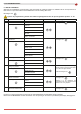
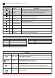
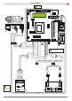
Trimmer Description
P1 Opening speed
P2 Closing speed
P3 Deceleration during opening
P4 Adjustment of deceleration during closure
P5 Adjustment of display contrast.
0 s 30 s
0 s 10 s
0 MAX
0 MAX
0 MAX
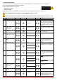
Dip-switches Description OFF ON
DIP 1 Future use – –
DIP 2 Access to advanced menu Disabled Enabled
DIP 3 Trimmer enabling Disabled Enabled
DIP 4
Counter
TOT: Number of operations
SVC: Number of operations left until service
Disabled Enabled
DIP 5 Access to service menu Disabled Enabled
DIP 6
Door operating data display
(F working, I Bus, I peak, V Bus)
Disabled Enabled
DIP 7 Future use – –
DIP 8 Cyclic operation menu Disabled Enabled
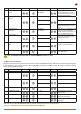
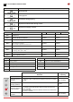
LED On
DL2 Closing position
DL3 Deceleration
DL6 Partial opening
DL7 Opening position
DL15 Autostart
Buttons Description
S2 USED FOR PROGRAMMING
S3 NOT USED
S4 NOT USED
S5 USED FOR PROGRAMMING
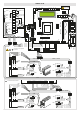
Operating mode
Standard
Programming
Operating
Button LED Button
Starts the opening
operation.
- The green LED on indicates the presence of the 24 V= power
supply.
Menu scrolling
Starts the partial
opening operation.
Conrm
Starts and stops the
STOP operation.
- The red LED on indicates that the STOP has been activated.
- The ashing red LED indicates that the safety devices have
been activated.
- The quick ashing red LED indicates that the service threshold
has been reached
Starts the closing
operation.
Menu scrolling
ON
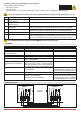
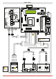
2. ADJUSTMENTS AND SETTINGS
52E
EN