
User Manual


- 38 -
0DT829 01-12-2021
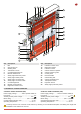
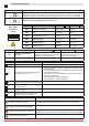
5.2 52E CONTROL PANEL (INVERTER) - Connections
INPUTS
Command Function Description
1
2 NC STOP If on the programming menu (page 15 point 16)
Contact 1-2 enabled, opening of the contact STOPS the door
1
3
NO
Opening
The closure of the contact activates the opening operation.
1
4
NO
Closure
The closure of the contact activates the closing operation.
41
40 NC Reversal safety
contact
Opening the safety contact triggers a reversal of the movement (reopening)
during the closing operation.
1
8 NC Reversal safety
contact
Opening the safety contact triggers a reversal of the movement (reopening)
during the closing operation.
1
20 NO Partial opening Closing of the contact activates a partial opening operation of the duration set
with the advanced menu.
1
11
NC Closing position Opening of the contact indicates the closing position. (max. 50 mA)
1
13
NC
Opening position
Opening of the contact indicates the opening position. (max. 50 mA)
OUTPUTS
Output Value Description
1
0
+
-
24 V = / 0. 5A
Power supply to accessories.
Power supply output for external accessories, including automation status
lamps.
LAMP
230 V~
Flashing light (FLM).
Non-ashing signal (jumper ON on FML).
Activated during opening and closing operations.
-F +F
24 V = / 0.5 A
Motor electric brake.
The output is active for the duration of both the opening and closing operation.
U W V
M
3 ~
230 V~ / 6 A Three-phase motor.
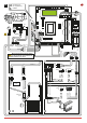
M2 Safety device / Commands
M3 Position signal
M4 Interlock
M4A Back
M5 Motor / brake motor
M6 Thermal motor
M7 Absolute encoder
J4 Brake resistance
OPEN Auxiliary panel card
SAFETY Auxiliary safety card
CONTROL PANEL CONNECTORS
52E