
User Manual


- 33 -
0DT829 01-12-2021
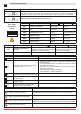
Correctly size the line conductor cross-section by referring to the indicated absorption and taking the length and
installation of the cables into account.
0 1
Tx1 Rx1
0 1
0 1
Tx2Rx2
0 1
A935G/E
A935L/N
7982
7982
A451L
A934E/L
A933A - 7823B
A931C - 7824B
7825A - C
7823A
7824A
7824A
7825A
7823C/D
7824C/D
7824C/D
9038
9036
9040
7825A - C
ENC
M F
T
Black
Blue
Black
Blue
Black
Blue
Orange
Red
Black
Blue
Orange
Red
C T
19
17 18
400 V
400 V
400 V
230 V
Inverter
230 V
Inverter
TRAFFIC C
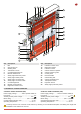
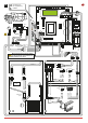
4. ELECTRICAL CONNECTIONS
4.1 Electrical panel
• Insert the cables with the pre-wired terminal boards in the housing (g. 17) and connect them to the boards (as shown in
chap. 5). Fit the cables in the conduit and connect the connectors on the motor (g.18).
Cabling connection on the board must be done with main power cut o, for at least 30 sec.
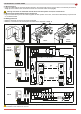
4.2 Electrical panel/motor/safety device connections
• Figure 19 shows the layout of the cables supplied and their position in the door; each cable is identied by a special code
on an adhesive label.
4.3 Safety photocells
• Make the electrical connections as shown in (g.19).
• Make the connections in the control panel as shown in the diagrams in chap. 5.
EN