R150/R230/R300 Operator’s Manual CMW® Issue 1.
R150/R230/R300 Operator’s Manual Overview - 1 Overview Chapter Contents Serial Number Location . . . . . . . . . . . . . . . . . . . . . . 2 Intended Use . . . . . . . . . . . . . . . . . . . . . . . . . . . . . . . 3 Equipment Modification . . . . . . . . . . . . . . . . . . . . . 3 Unit Components . . . . . . . . . . . . . . . . . . . . . . . . . . . 4 Operator Orientation. . . . . . . . . . . . . . . . . . . . . . . . . 4 About This Manual . . . . . . . . . . . . . . . . . . . . . . . . . .
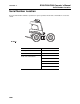
R150/R230/R300 Operator’s Manual Overview - 2 Serial Number Location Serial Number Location Record serial numbers and date of purchase in spaces provided. Power unit serial number is located as shown.
R150/R230/R300 Operator’s Manual Overview - 3 Intended Use Intended Use The Zahn line consists of three versatile performers. The R150 is configured as a dedicated trencher. The R230 and R300 units can be configured as dedicated trenchers or they can be configured with an InterChange connection to allow them to accept a variety of front ends. Available interchangeable front ends include a trencher, vibratory plow, dumper, tool carrier, backhoe, stump grinder and tiller.
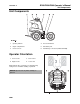
R150/R230/R300 Operator’s Manual Overview - 4 Unit Components Unit Components 1. operator platform 4. front end manifold 2. engine compartment 5. articulation joint 3. control console 6. InterChange connection (R230 and R300) Operator Orientation 1. Front of unit 3. Rear of unit 2. Right of unit 4. Left of unit Right and left sides of machine are determined by facing front of unit while standing on platform. NOTICE: Operate unit only while standing on platform.
R150/R230/R300 Operator’s Manual Overview - 5 About This Manual About This Manual This manual contains information for the proper use of this machine. See Operation Overview for basic operating procedures. Cross references such as “See page 50” will direct you to detailed procedures. Bulleted Lists Bulleted lists provide helpful or important information or contain procedures that do not have to be performed in a specific order.
Overview - 6 R150/R230/R300 Operator’s Manual About This Manual CMW
R150/R230/R300 Operator’s Manual Foreword - 7 Foreword This manual is an important part of your equipment. It provides safety information and operation instructions to help you use and maintain your Ditch Witch equipment. Read this manual before using your equipment. Keep it with the equipment at all times for future reference. If you sell your equipment, be sure to give this manual to the new owner. If you need a replacement copy, contact your Ditch Witch dealer or download it at www.ditchwitch.com.
Foreword - 8 R150/R230/R300 Operator’s Manual R150/R230/R300 Operator’s Manual Issue number 1.6/OM-9/09 Part number 053-1173 Copyright 2007, 2008, 2009 by The Charles Machine Works, Inc. , Ditch Witch, CMW, AutoCrowd, Jet Trac, Roto Witch, Subsite, Fluid Miser, Power Pipe, Super Witch, Pierce Airrow, The Underground, The Underground Authority Worldwide, and Zahn are registered trademarks of The Charles Machine Works, Inc. This product is covered by the following patent: U.S. 7,621,366; other U.S.
R150/R230/R300 Operator’s Manual Contents - 9 Contents Overview 1 machine serial number, information about the type of work this machine is designed to perform, basic machine components, and how to use this manual Foreword 7 part number, revision level, and publication date of this manual, and factory contact information Safety 11 machine safety alerts and emergency procedures Controls 21 machine controls, gauges, and indicators and how to use them Prepare 33 procedures for inspecting and cl
Contents - 10 R150/R230/R300 Operator’s Manual Support 99 the warranty policy for this machine, and procedures for obtaining warranty consideration and training Service Record a record of major service performed on the machine CMW 103
R150/R230/R300 Operator’s Manual Safety - 11 Safety Chapter Contents Guidelines . . . . . . . . . . . . . . . . . . . . . . . . . . . . . . . . 12 Safety Alert Classifications . . . . . . . . . . . . . . . . . . 13 Safety Alerts . . . . . . . . . . . . . . . . . . . . . . . . . . . . . . 14 Emergency Procedures . . . . . . . . . . . . . . . . . . . . . 17 • Electric Strike Description . . . . . . . . . . . . . . . . . . . . . . . . . . . . . . . . . . .17 • If an Electric Line is Damaged . . . . . . .
Safety - 12 R150/R230/R300 Operator’s Manual Guidelines Guidelines Follow these guidelines before operating any jobsite equipment: • Complete proper training and read operator’s manual before using equipment. • Contact your local One-Call (811 in USA) or the One-Call referral number ( 888-258-0808 in USA and Canada) to have underground utilities located before digging. Also contact any utilities that do not participate in the One-Call service.
R150/R230/R300 Operator’s Manual Safety - 13 Safety Alert Classifications Safety Alert Classifications These classifications and the icons defined on the following pages work together to alert you to situations which could be harmful to you, jobsite bystanders or your equipment. When you see these words and icons in the book or on the machine, carefully read and follow all instructions. YOUR SAFETY IS AT STAKE. Watch for the three safety alert levels: DANGER, WARNING and CAUTION.
R150/R230/R300 Operator’s Manual Safety - 14 Safety Alerts Safety Alerts Moving digging teeth will kill you or cut off arm or leg. Stay away. Turning shaft will kill you or crush arm or leg. Stay away. Electric shock. Contacting electric lines will cause death or serious injury. Know location of lines and stay away. Deadly gases. Lack of oxygen or presence of gas will cause sickness or death. Provide ventilation. Jobsite hazards could cause death or serious injury.
R150/R230/R300 Operator’s Manual Safety - 15 Safety Alerts Explosion possible. Serious injury or equipment damage could occur. Follow directions carefully. Incorrect procedures could result in death, injury, or property damage. Learn to use equipment correctly. Improper control function could cause death or serious injury. If control does not work as described in instructions, stop machine and have it serviced. Looking into fiber optic cable could result in permanent vision damage.
R150/R230/R300 Operator’s Manual Safety - 16 Safety Alerts Tipover possible. Machine can tip over and crush you. • Always operate with load end uphill. • Always carry load low. High load can cause tipping, loss of load or loss of visibility. • Never jerk control levers. Use a steady even motion. Flying objects may cause injury. Wear hard hat and safety glasses. Hot parts may cause burns. Do not touch until cool. Exposure to high noise levels may cause hearing loss. Wear hearing protection.
R150/R230/R300 Operator’s Manual Safety - 17 Emergency Procedures Emergency Procedures Before operating any equipment, review emergency procedures and check that all safety precautions have been taken. EMERGENCY SHUTDOWN: Release all controls (including cruise control pedal) and turn ignition switch to OFF. Electric Strike Description When working near electric cables, remember the following: • Electricity follows all paths to ground, not just path of least resistance.
Safety - 18 R150/R230/R300 Operator’s Manual Emergency Procedures If an Electric Line is Damaged If you suspect an electric line has been damaged and you are on platform, DO NOT MOVE. Remain on platform and take the following actions. The order and degree of action will depend upon the situation. • Warn people nearby that an electric strike has occurred. Instruct them to leave the area and contact utility. • Raise front end and attachments and drive from immediate area.
R150/R230/R300 Operator’s Manual Safety - 19 Emergency Procedures If a Fiber Optic Cable is Damaged Do not look into cut ends of fiber optic or unidentified cable. Vision damage can occur. If Machine Catches on Fire Perform emergency shutdown procedure and then take the following actions. The order and degree of action will depend on the situation. • Immediately move battery disconnect switch (if equipped) to disconnect position.
Safety - 20 R150/R230/R300 Operator’s Manual Emergency Procedures CMW
R150/R230/R300 Operator’s Manual Controls - 21 Controls Chapter Contents Gauges and Indicators . . . . . . . . . . . . . . . . . . . . . 22 Controls . . . . . . . . . . . . . . . . . . . . . . . . . . . . . . . . . 24 • R150/R150E . . . . . . . . . . . . . . . . . . . . . . . . . . . . . . . . . . . . . . . . . . . . . .24 • R230/R300 . . . . . . . . . . . . . . . . . . . . . . . . . . . . . . . . . . . . . . . . . . . . . . .28 • R150/R230/R300 . . . . . . . . . . . . . . . . . . . . . . . . . . . .
R150/R230/R300 Operator’s Manual Controls - 22 Gauges and Indicators Gauges and Indicators 1. Auxiliary power outlet (R150E/R230/R300 only) 3. Hydraulic fluid sight glass 4. Hourmeter (optional) 2. Fuel sight glass Item Description Notes 1. Auxiliary power outlet To operate work lights or other 12V devices, plug into outlet. Not available on R150 with rope start. 2. Fuel tank sight window Shows level of fuel in tank. 3. Hydraulic fluid sight glass Shows level of hydraulic fluid in tank.
R150/R230/R300 Operator’s Manual Controls - 23 Gauges and Indicators Item Description Notes 4. Hourmeter (optional) Displays engine operating time. Use these times to schedule service.
Controls - 24 R150/R230/R300 Operator’s Manual Controls Controls R150/R150E 1. Ground drive control 6. Choke (R150)/manual start switch (R150E) 2. Traction assist switch 7. Rope start 3. Throttle switch 8. Ignition switch 4. Front end lift control 9. Parking brake 5. Front end drive control 10.
R150/R230/R300 Operator’s Manual Controls - 25 Controls Item Description Notes 1. Ground drive control To move forward, push. To make a gradual turn, move control halfway between desired directions and return to center. Unit will remain articulated until it is returned to center. To move backward, pull. To turn right, move to right. To turn left, move to left. IMPORTANT: As long as control is moved to right or left, unit is articulating and turning is tightened.
R150/R230/R300 Operator’s Manual Controls - 26 Controls Item Description 5. Front end drive control To engage front end drive in reverse, lift lever release and move to right. Notes To engage front end drive in forward, lift lever release and move to left. 6. Choke/manual start switch Choke (R150) This valve regulates air/fuel mixture. To help start cold engine, close valve. Manual start switch (R150E) IMPORTANT: R150E units have automatic choke feature.
R150/R230/R300 Operator’s Manual Controls - 27 Controls Item Description Notes 9. Parking brake lever To engage, move handle to left. IMPORTANT: To disengage, move handle to right. 10. Cruise control pedal To maintain ground drive and front end drive settings, press pedal and release handles. • Move unit slightly to ensure parking brake pins are engaged. • It might be necessary to move unit slightly to disengage parking brake. NOTICE: Pedal must return to neutral when released.
Controls - 28 R150/R230/R300 Operator’s Manual Controls R230/R300 1. Ground drive control 6. Choke 2. Traction assist switch 7. Throttle 3. Front end lift control 8. Ignition switch 4. Front end drive control 9. Parking brake 5. Remote throttle control (optional) 10.
R150/R230/R300 Operator’s Manual Controls - 29 Controls Item Description Notes 1. Ground drive control To move forward, push. To make a gradual turn, move control halfway between desired directions and return to center. Unit will remain articulated until it is returned to center. To move backward, pull. To turn right, move to right. To turn left, move to left. IMPORTANT: As long as control is moved to right or left, unit is articulating and turning is tightened.
R150/R230/R300 Operator’s Manual Controls - 30 Controls Item Description Notes 5. Remote throttle control (optional) To increase engine speed, push. NOTICE: R300 units must be stopped at full throttle to prevent backfiring. To decrease engine speed, pull. 6. Choke To help start cold engine, move to left. This valve regulates air/fuel mixture. Move to right after engine has warmed. 7. Throttle 8. Ignition switch 9. Parking brake lever To increase engine speed, move to left.
R150/R230/R300 Operator’s Manual Controls - 31 Controls Item Description Notes 10. Cruise control pedal To maintain ground drive and front end drive settings, press pedal and release handles. NOTICE: Pedal must return to neutral when released. Never tie down or use anything other than foot to hold pedal down. To adjust settings, grab drive handles, step off pedal, adjust drive settings, press pedal and release handles.
Controls - 32 R150/R230/R300 Operator’s Manual Controls R150/R230/R300 1. Articulation lock To lock articulation joint, align top and bottom holes and put pin in hole (shown). Lock for transporting and lifting. Unlock to maneuver unit. To unlock articulation joint, return pin to storage hole.
R150/R230/R300 Operator’s Manual Prepare - 33 Prepare Chapter Contents Gather Information . . . . . . . . . . . . . . . . . . . . . . . . . 34 Inspect Site . . . . . . . . . . . . . . . . . . . . . . . . . . . . . . . 35 • Identify Hazards . . . . . . . . . . . . . . . . . . . . . . . . . . . . . . . . . . . . . . . . . . .35 Classify Jobsite . . . . . . . . . . . . . . . . . . . . . . . . . . . 36 • Inspect Jobsite . . . . . . . . . . . . . . . . . . . . . . . . . . . . . . . . . . . . . . . . . . . .
Prepare - 34 R150/R230/R300 Operator’s Manual Gather Information Gather Information A successful job begins before you start working. The first step in planning is reviewing information already available about the job and jobsite. Review Job Plan Review blueprints or other plans. Check for information about existing or planned structures, elevations, or proposed work that may be taking place at the same time.
R150/R230/R300 Operator’s Manual Prepare - 35 Inspect Site Inspect Site Inspect jobsite before transporting equipment. Check for the following: • changes in elevation such as hills or other open trenches • obstacles such as buildings, railroad crossings, or streams • signs of utilities (See “Inspect Jobsite” on page 36.) • traffic • access • soil type and condition Identify Hazards Identify safety hazards and classify jobsite if front end or attachment will penetrate ground.
Prepare - 36 R150/R230/R300 Operator’s Manual Classify Jobsite Classify Jobsite Inspect Jobsite • Inspect jobsite and perimeter for evidence of underground hazards, such as: – “buried utility” notices – utility facilities without overhead lines – gas or water meters – junction boxes – drop boxes – light poles – manhole covers – sunken ground • Follow U.S. Department of Labor regulations on excavating and trenching (Part 1926, Subpart P) and other similar regulations.
R150/R230/R300 Operator’s Manual Prepare - 37 Classify Jobsite Apply Precautions Once classified, precautions appropriate for jobsite must be taken. Electric Jobsite Precautions Use one or both of these methods. • Expose line by careful hand digging or soft excavation. • Have service shut down while work is in progress. Have electric company test lines before returning them to service.
Prepare - 38 R150/R230/R300 Operator’s Manual Check Supplies and Prepare Equipment Check Supplies and Prepare Equipment Supplies • fuel • lubricants Fluid Levels • fuel • hydraulic fluid • battery charge • engine oil Condition and Function • parking brake pins (see “Check Parking Brake Operation” on page 65) • filters (air, oil, hydraulic) • pumps and motors • hoses and valves • signs, guards, and shields Accessories Fire Extinguisher Mount a fire extinguisher near the power unit but
R150/R230/R300 Operator’s Manual Drive - 39 Drive Chapter Contents Start Unit . . . . . . . . . . . . . . . . . . . . . . . . . . . . . . . . . 40 Drive . . . . . . . . . . . . . . . . . . . . . . . . . . . . . . . . . . . . 41 Shut Down . . . . . . . . . . . . . . . . . . . . . . . . . . . . . . .
Drive - 40 R150/R230/R300 Operator’s Manual Start Unit Start Unit EMERGENCY SHUTDOWN: Release all controls (including cruise control pedal) and turn ignition switch to OFF. R150 1. Ensure all controls are in neutral and parking brake is engaged. 2. Turn key to on position. 3. Move throttle switch to center position. 4. Choke engine, if necessary. 5. Pull rope or turn ignition switch to start position and release when engine starts. R230/R300 1.
R150/R230/R300 Operator’s Manual Drive - 41 Drive Drive Incorrect procedures could result in death, injury, or property damage. Learn to use equipment correctly. NOTICE: Operate unit only while standing on platform. General Operation Tipover possible. Machine can tip over and crush you. • Always operate with load end uphill. • Always carry load low. High load can cause tipping, loss of load or loss of visibility. • Never jerk control levers. Use a steady even motion. 1. Disengage parking brake. 2.
Drive - 42 R150/R230/R300 Operator’s Manual Shut Down Shut Down 1. Lower front end to ground. 2. Move all controls to neutral position. 3. Engage parking brake. 4. Move throttle to center position (R150) or to full open (R230/R300). 5. Turn ignition switch to OFF. 6. Remove key.
R150/R230/R300 Operator’s Manual Transport - 43 Transport Chapter Contents Lift . . . . . . . . . . . . . . . . . . . . . . . . . . . . . . . . . . . . . . 44 • Points . . . . . . . . . . . . . . . . . . . . . . . . . . . . . . . . . . . . . . . . . . . . . . . . . . .44 • Procedure . . . . . . . . . . . . . . . . . . . . . . . . . . . . . . . . . . . . . . . . . . . . . . . .45 Haul . . . . . . . . . . . . . . . . . . . . . . . . . . . . . . . . . . . . . 46 • Load . . . . . . . . . . . . . . . . .
Transport - 44 R150/R230/R300 Operator’s Manual Lift Lift Crushing weight. If load falls or moves it could kill or crush you. Use proper procedures and equipment or stay away. Points Lifting points are identified by lifting decals. Lifting at other points is unsafe and can damage machinery.
R150/R230/R300 Operator’s Manual Transport - 45 Lift Procedure Use a hoist capable of supporting the equipment's size and weight. See “Specifications” on page 81 or measure and weigh equipment before lifting. Configured trencher Configured 4-wheel drive unit only Lock articulation joint and use three lift points as shown. Lock articulation joint and use four lift points as shown. To lift configured 4-wheel drive unit with front end, see appropriate front end operation sheet.
R150/R230/R300 Operator’s Manual Transport - 46 Haul Haul IMPORTANT: For trailer information, see the trailer manufacturer’s manual. Load Crushing weight. If load falls or moves it could kill or crush you. Use proper procedures and equipment or stay away. Tipover possible. Machine can tip over and crush you. • Always operate with heavy end uphill. • Lock articulation joint when transporting. IMPORTANT: Do not remove front end from InterChange connection before loading or unloading power unit. 1.
R150/R230/R300 Operator’s Manual Transport - 47 Haul Tie Down Points Tiedown points are identified by tiedown decals. Securing to truck or trailer at other points is unsafe and can damage machinery. Procedure Configured Trencher Loop tiedowns around unit at tiedown points. Make sure tiedowns are tight before transporting. Other Front Ends To tie down unit with any other front end, see appropriate front end operation sheet.
R150/R230/R300 Operator’s Manual Transport - 48 Haul Unload Crushing weight. If load falls or moves it could kill or crush you. Use proper procedures and equipment or stay away. Tipover possible. Machine can tip over and crush you. Always operate with heavy end uphill. IMPORTANT: Do not remove front end from InterChange connection before loading or unloading power unit. 1. Lower trailer or ramps and remove tiedowns. 2. Unlock articulation joint. 3. Open fuel tank shutoff valve. 4.
R150/R230/R300 Operator’s Manual Transport - 49 Tow Tow Under normal conditions, unit should not be towed. If unit breaks down and towing is necessary: • attach chains to tow point (shown) facing towing vehicle • tow for short distances at less than 1 mph (1.
Transport - 50 R150/R230/R300 Operator’s Manual Tow Prepare Unit for Towing 1. Ensure parking brake is engaged. 2. Block wheels. 3. Connect to tow point. 4. Turn tow valve (shown). • R150 (top illustration): Turn counterclockwise two turns. • R230/R300 (bottom illustration): Turn counterclockwise 1/4 turn. 5. Disengage parking brake. See “Parking brake lever” on page 27. 6. Unblock wheels. Return Unit to Normal Operation 1. Engage parking brake. 2. Block wheels. 3. Disconnect from tow point. 4.
R150/R230/R300 Operator’s Manual Trench - 51 Trench Chapter Contents Trench . . . . . . . . . . . . . . . . . . . . . . . . . . . . . . . . . . .
R150/R230/R300 Operator’s Manual Trench - 52 Electrical shock. Contacting electrical lines will cause death or serious injury. Know location of lines and stay away. NOTICE: Cutting high voltage cable can cause electrocution. Expose lines by hand before digging. Incorrect procedures could result in death, injury, or property damage. Learn to use equipment correctly. NOTICE: • Comply with all utility notification regulations before digging or drilling.
R150/R230/R300 Operator’s Manual Trench - 53 Trench Trench Moving digging teeth will cause death or serious injury. Stay away. NOTICE: • Keep everyone at lease 6’ (2 m) from machine, digging boom, and its range of movement. • Machine may move when chain starts to dig. Allow 3’ (1 m) between end of chain and obstacle. • Operate unit only while standing on platform. 1. Move unit to starting point of trench.
Trench - 54 R150/R230/R300 Operator’s Manual Trench 7. Disengage parking brake and pull ground drive control to begin trenching. UNIT WILL MOVE. IMPORTANT: • Trenching movement is toward you. • For easier turning, lower boom to full depth. • If an object becomes lodged in chain, move digging chain control to neutral and raise boom slightly. Reverse chain direction. If object must be removed manually, stop engine. 8. For continuous ground drive and front end drive operation, use cruise control pedal.
R150/R230/R300 Operator’s Manual Systems and Equipment - 55 Systems and Equipment Chapter Contents Chain, Teeth, and Sprockets . . . . . . . . . . . . . . . . . 56 • Chain and Tooth Maintenance . . . . . . . . . . . . . . . . . . . . . . . . . . . . . . . .56 • Chain Types . . . . . . . . . . . . . . . . . . . . . . . . . . . . . . . . . . . . . . . . . . . . . .56 • Chain Selection . . . . . . . . . . . . . . . . . . . . . . . . . . . . . . . . . . . . . . . . . . .57 Optional Equipment . . . . . .
Systems and Equipment - 56 R150/R230/R300 Operator’s Manual Chain, Teeth, and Sprockets Chain, Teeth, and Sprockets Chain and Tooth Maintenance • Always replace sprockets at the same time you replace the digging chain. Sprockets and chain are designed to work together. Replacing one without the other will cause premature wear of the new part. • Keep digging teeth sharp. Using dull, worn teeth will decrease production and increase shock load to other trencher components.
R150/R230/R300 Operator’s Manual Systems and Equipment - 57 Chain, Teeth, and Sprockets Chain Selection These charts are meant as a guideline only. No one chain type works well in all conditions. See your Ditch Witch dealer for soil conditions and chain recommendations for your area. Ask for the latest Chain, Teeth, and Sprockets Parts Catalog.
Systems and Equipment - 58 R150/R230/R300 Operator’s Manual Optional Equipment Optional Equipment See your Ditch Witch dealer for information about available optional equipment.
R150/R230/R300 Operator’s Manual Complete the Job - 59 Complete the Job Chapter Contents Restore Jobsite . . . . . . . . . . . . . . . . . . . . . . . . . . . . 60 • Backfilling . . . . . . . . . . . . . . . . . . . . . . . . . . . . . . . . . . . . . . . . . . . . . . . .60 Rinse Equipment . . . . . . . . . . . . . . . . . . . . . . . . . . 60 Stow Tools . . . . . . . . . . . . . . . . . . . . . . . . . . . . . . .
Complete the Job - 60 R150/R230/R300 Operator’s Manual Restore Jobsite Restore Jobsite After product is installed, return spoils to the trench with optional backfill blade. Backfilling 1. Turn off engine. 2. Install backfill blade and secure with pull pins, as shown. 3. Start unit. 4. Position unit at end of trench, several feet from spoils. Aim unit at outer edge of spoils. 5. Adjust backfill blade to fit land contour. 6. Move outer edge of spoils toward trench.
R150/R230/R300 Operator’s Manual Service - 61 Service Chapter Contents Service Precautions . . . . . . . . . . . . . . . . . . . . . . . . 62 Recommended Lubricants/Service Key . . . . . . . . 62 Oil Temperature Chart . . . . . . . . . . . . . . . . . . . . . . 63 Each Use . . . . . . . . . . . . . . . . . . . . . . . . . . . . . . . . . 64 10 Hour . . . . . . . . . . . . . . . . . . . . . . . . . . . . . . . . . . 66 20 Hour . . . . . . . . . . . . . . . . . . . . . . . . . . . . . . . . . . 69 50 Hour .
R150/R230/R300 Operator’s Manual Service - 62 Service Precautions Service Precautions Incorrect procedures could result in death, injury, or property damage. Learn to use equipment correctly. NOTICES: • Unless otherwise instructed, all service should be performed with engine off. • Refer to engine manufacturer’s manual for engine maintenance instructions. • Before servicing equipment, lower unstowed front ends to ground.
R150/R230/R300 Operator’s Manual Service - 63 Engine Oil Temperature Chart Engine Oil Temperature Chart R150 Temperature range anticipated before next oil change R230/R300 Temperature range anticipated before next oil change For more information on engine lubrication and maintenance, see your engine manual.
R150/R230/R300 Operator’s Manual Service - 64 Each Use Each Use Location Task Notes Power Unit Check engine oil level GEO Check hydraulic fluid level THF Check parking brake operation Check tires Power Unit Check Engine Oil Level - R150 Check engine oil at dipstick (1) before each use. If low, add GEO until oil level is at highest line on dipstick. IMPORTANT: For more information on engine oil, see “Recommended Lubricants/Service Key” on page 62 or see engine manual.
R150/R230/R300 Operator’s Manual Service - 65 Each Use Check Hydraulic Fluid Level With digging boom fully raised, check hydraulic fluid level at sight glass (2) before each use. If low, add THF until level is at halfway point on sight glass. Clean dust from cap (1) by blowing with low pressure air. Check Parking Brake Operation Verify that parking brake pins engage as shown before each use. Check Tires Check power unit tire pressure (2, if necessary) before each use.
R150/R230/R300 Operator’s Manual Service - 66 10 Hour 10 Hour Location Task Power Unit Check hydraulic hoses Trencher Notes Inspect insulation R150 only Lube trencher pivot MPG Lube trencher headshaft bearing MPG Check digging chain tension MPG Power Unit Check Hydraulic Hoses Check hydraulic hoses for leaks every 10 hours. Fluid or air pressure could pierce skin and cause injury or death. Stay away. NOTICE: Escaping pressurized fluid can cause injury or pierce skin and poison.
R150/R230/R300 Operator’s Manual Service - 67 10 Hour Inspect Insulation (R150 units only) Inspect heat insulation on R150 fuel tank (1) and fuel line (2) for damage every 10 hours. Replace if damaged. 1 Trencher 2 t22om001t.eps Lube Trencher Pivot Lube two pivot zerks with MPG every 10 hours. Lube Headshaft Bearings Lube headshaft bearing with MPG every 10 hours. t22om001t.
R150/R230/R300 Operator’s Manual Service - 68 10 Hour Check Digging Chain Tension NOTICE: Do not overtighten chain. Overtightening will cause chain stretch, loss of machine performance, and possible premature chain failure. Check digging chain tension every 10 hours and adjust as needed. With boom horizontal, measure distance from bottom of boom to chain. When properly tensioned, distance (A) should be 1.5” (38 mm). Adjustment Screw: 1. Loosen four clamp bolts (2) so that boom slides freely. 2.
R150/R230/R300 Operator’s Manual Service - 69 20 Hour 20 Hour Location Task Notes Power Unit Change engine oil - R150 Initial service, GEO Change engine oil and filter - R230/R300 Initial service, GEO Lube trail wheel MPG Lube headshaft bearing MPG, headshaft auger trencher only Trencher Power Unit Change Engine Oil (Initial) - R150 Change engine oil after the first 20 hours of operation. 1. Move drain hose (1) to front of unit and drain while oil is still warm. 2. Replace plug. 3. Add 1.
Service - 70 R150/R230/R300 Operator’s Manual 20 Hour Change Engine Oil and Filter (Initial) R230/R300 Change engine oil and filter after the first 20 hours of operation. 1. Move drain hose (1) to front of unit and drain while oil is still warm. 2. Replace plug. 3. Install new filter (3). 4. Add 2 qt (1.9 L) of GEO at fill neck (2). IMPORTANT: If operating in extremely dusty conditions, change oil more frequently.
R150/R230/R300 Operator’s Manual Service - 71 50 Hour Lube Headshaft Bearing (Headshaft Auger Trencher Only) Lube headshaft bearing with MPG every 20 hours. 50 Hour Location Task Notes Power Unit Check battery if equipped Trencher Lube digging boom adjustment screw and stub, if equipped MPG Lube digging boom stub, if equipped MPG Power Unit Check Battery Check battery every 50 hours. Keep battery case and terminals clean. Remove all corrosion from terminals with a wire brush.
Service - 72 R150/R230/R300 Operator’s Manual 50 Hour Trencher Lube Digging Boom Adjustment Screw and Stub Lube adjustment screw and stub with MPG every 50 hours. Lube Digging Boom Stub (Greaseable Boom) Lube boom stub with MPG every 50 hours.
R150/R230/R300 Operator’s Manual Service - 73 100 Hour 100 Hour Location Task Notes Power Unit Change engine oil - R150 GEO Change engine oil and filter - R230/R300 GEO Change air filter Power Unit Change Engine Oil - R150 Change engine oil every 100. 1. Move drain hose (1) to front of unit and drain while oil is still warm. 2. Replace plug. 3. Add 1.6 qt (1.1 L) of GEO at fill neck (2). IMPORTANT: If operating in extremely dusty conditions, change oil more frequently.
Service - 74 R150/R230/R300 Operator’s Manual 100 Hour Change Air Filter - R150 Change air filter elements every 100 hours. IMPORTANT: If operating in extremely dusty conditions, change filter more frequently. To change: 1. Remove wing nut (6) and air cleaner cover (5). 2. Remove wing nut (4) and remove elements (2, 3). 3. Reverse procedure to install new elements. Ensure gasket (1) is seated properly. Change Air Filter - R230/R300 Change air filter elements every 100 hours.
R150/R230/R300 Operator’s Manual Service - 75 250 Hour 250 Hour Location Task Notes Power Unit Change hydraulic fluid and filter THF Change fuel filter Power Unit Change Hydraulic Fluid and Filter Change hydraulic fluid and filter every 250 hours. 1. Drain hydraulic fluid at drain (3). 2. Replace plug. 3. Change filter (shown). 4. Add THF at fill neck (1, above) until level is at halfway point on sight glass (2, above).
Service - 76 R150/R230/R300 Operator’s Manual 250 Hour Change Fuel Filter Close fuel tank shutoff (top illustration) and change fuel filter (bottom illustration) every 200 hours. Open fuel tank shutoff before operating unit.
R150/R230/R300 Operator’s Manual Service - 77 500 Hour 500 Hour Adjust Ground Drive Pump Neutral (R230/R300 only) Adjust neutral on ground drive pump every 500 hours or if spring is rusted or worn. Check adjustment with throttle at low speed and hydraulic fluid at operating temperature. Ensure all neutral components are working properly before adjusting. To adjust 1. Use a hoist or appropriate jack stands to reaise unit until all tires are off the ground. 2. Loosen bolts (1). 3.
R150/R230/R300 Operator’s Manual Service - 78 As Needed As Needed Location Task Notes Power Unit Change fuses 15A, 30A Clean cooler and screen Adjust ground drive pump speed Adjust ground drive pump neutral Set cruise control brake Adjust cruise control brake Power Unit Change Fuses Change fuses as needed. • blue with red stripe wire is 15A • orange with blue stripe wire is 30A Clean Cooler and Screen Clean hydraulic fluid cooler and screen as needed.
R150/R230/R300 Operator’s Manual Service - 79 As Needed Adjust Ground Drive Pump Speed (R230/R300 only) Adjust ground drive pump speed as desired. To adjust 1. Remove nut (1) and lock washer. 2. Move linkage (2) to hole that corresponds with desired speed range. • A is low • B is medium • C is high 3. Tighten nut. Set Cruise Control Brake Engage or disengage cruise control brake as desired. To engage, set arm as shown (A). To disengage, move arm to slot (B).
Service - 80 R150/R230/R300 Operator’s Manual As Needed Adjust Cruise Control Brake Adjust cruise control brake as desired. Loose brake allows more override. Tight brake allows less override. To adjust 1. Open arm (4) and remove pin. 2. Rotate linkage (1) counterclockwise to tighten or clockwise to loosen. 3. If brake is still loose, loosen jam nut (2) and turn screw (3) clockwise to tighten and counterclockwise to loosen brake. 4. Rotate linkage as needed to adjust. 5. Reinstall arm.
R150/R230/R300 Operator’s Manual Specifications - 81 Specifications Chapter Contents R150 . . . . . . . . . . . . . . . . . . . . . . . . . . . . . . . . . . . . 82 R230 with InterChange Connection . . . . . . . . . . . 85 R300 with InterChange Connection . . . . . . . . . . . 89 Power Unit with Headshaft Auger Trencher . . . . 93 Power Unit with Independent Auger Trencher . .
Specifications - 82 R150/R230/R300 Operator’s Manual R150 R150 Dimensions U.S. Metric L Length 43 in 1.09 m L6 Tractor back to rear axle 26.8 in 681 mm L7 Rear axle to front end mounting 19.2 in 488 mm H Height 53.5 in 1.36 m H4 Ground clearance 5.3 in 135 mm H10 Platform height 10.7 in 272 mm W Width 36 in 914 mm A Angle of departure 25° 25° R150 968 lb 439 kg R150E 1010 lb 458 kg Right turn 11.3 ft 3.44 m Left turn 10.5 ft 3.
R150/R230/R300 Operator’s Manual Specifications - 83 R150 Operation U.S. Metric Ground drive speed, forward 3.3 mph 5.3 km/h Ground drive speed, reverse 3.3 mph 5.3 km/h Ground pressure 16 psi 1.2 bar Power U.S. Metric Engine: Honda iGX440, gasoline Cooling medium air Number of cylinders 1 Displacement 26.7 in3 438 cc Bore 3.46 in 88 mm Stroke 2.84 in 72.1 mm Manufacturer’s power rating 15 hp 9.
Specifications - 84 R150/R230/R300 Operator’s Manual R150 Hydraulic System U.S. Metric Flow rate 7.4 gpm 28 L/min Pressure 3000 psi 207 bar Flow rate 11.4 gpm 43.2 L/min Pressure 1800 psi 124 bar Fluid Capacities U.S. Metric Fuel tank 10.9 gal 41.3 L Engine oil 1.6 qt 1.1 L Hydraulic reservoir 7.7 gal 29.1 L Total hydraulic system volume 8.5 gal 32.
R150/R230/R300 Operator’s Manual Specifications - 85 R230 with InterChange Connection R230 with InterChange Connection Dimensions U.S. Metric L Driving length 70 in 1.78 m L5 Wheelbase 34.2 in 869 mm L6 Tractor back to rear axle 26.8 in 681 mm L7 Rear axle to front end mounting 19.2 in 488 mm L8 Front end mounting to front axle 15 in 381 mm H Height 53.5 in 1.36 m H4 Ground clearance 5.3 in 135 mm H10 Platform height 10.
Specifications - 86 R150/R230/R300 Operator’s Manual R230 with InterChange Connection Operation (based on 18” tires) U.S. Metric Low 3.5 mph 5.6 km/h High 5.0 mph 8.0 km/h Low 3.5 mph 5.6 km/h High 5.0 mph 8.0 km/h Ground pressure 10 psi 0.7 bar Power U.S. Metric Ground drive speed, forward Ground drive speed, reverse Engine: Kohler CH23S, gasoline Cooling medium air Number of cylinders 2 Displacement 41.1 in3 674 cc Bore 3.15 in 80 mm Stroke 2.
R150/R230/R300 Operator’s Manual Specifications - 87 R230 with InterChange Connection Tires U.S. Metric Pressure 12 psi 82.7 kpa Tire assembly mass 22 lb 9.98 kg Pressure n/a n/a Tire assembly mass 36 lb 16.33 kg Pressure n/a n/a Tire assembly mass 49 lb 22.23 kg Pressure 22 psi 151 kpa Tire assembly mass 20 lb 9.07 kg U.S. Metric Flow rate 12 gpm 46 L/min Pressure 3000 psi 207 bar Flow rate 19.3 gpm 73 L/min Pressure 3500 psi 241 bar 18 X 9.
Specifications - 88 R150/R230/R300 Operator’s Manual R230 with InterChange Connection Fluid Capacities U.S. Metric Fuel tank 10.9 gal 41.3 L Engine oil, with filter 2 qt 1.9 L Hydraulic reservoir 7.7 gal 29.1 L Total hydraulic system volume 8.5 gal 32.
R150/R230/R300 Operator’s Manual Specifications - 89 R300 with InterChange Connection R300 with InterChange Connection Dimensions U.S. Metric L Driving length 70 in 1.78 m L5 Wheelbase 34.2 in 869 mm L6 Tractor back to rear axle 26.8 in 681 mm L7 Rear axle to front end mounting 19.2 in 488 mm L8 Front end mounting to front axle 15 in 381 mm H Height 53.5 in 1.36 m H4 Ground clearance 5.3 in 135 mm H10 Platform height 10.
Specifications - 90 R150/R230/R300 Operator’s Manual R300 with InterChange Connection Operation (based on 18” tires) U.S. Metric Low 3.5 mph 5.6 km/h High 5.0 mph 8.0 km/h Low 3.5 mph 5.6 km/h High 5.0 mph 8.0 km/h Ground pressure 10 psi 0.7 bar Power U.S. Metric Ground drive speed, forward Ground drive speed, reverse Engine: Kohler CH750S, gasoline Cooling medium air Number of cylinders 2 Displacement 45.6 in3 747 cc Bore 3.3 in 83 mm Stroke 2.
R150/R230/R300 Operator’s Manual Specifications - 91 R300 with InterChange Connection Tires U.S. Metric Pressure 12 psi 82.7 kpa Tire assembly mass 22 lb 9.98 kg Pressure n/a n/a Tire assembly mass 36 lb 16.33 kg Pressure n/a n/a Tire assembly mass 49 lb 22.23 kg Pressure 22 psi 151 kpa Tire assembly mass 20 lb 9.07 kg U.S. Metric Flow rate 12 gpm 46 L/min Pressure 3000 psi 207 bar Flow rate 19.3 gpm 73 L/min Pressure 3500 psi 241 bar 18 X 9.
Specifications - 92 R150/R230/R300 Operator’s Manual R300 with InterChange Connection Fluid Capacities U.S. Metric Fuel tank 10.9 gal 41.3 L Engine oil, with filter 2 qt 1.9 L Hydraulic reservoir 7.7 gal 29.1 L Total hydraulic system volume 8.5 gal 32.
R150/R230/R300 Operator’s Manual Specifications - 93 Power Unit with Headshaft Auger Trencher Power Unit with Headshaft Auger Trencher Dimensions U.S. Metric L Driving length 90.5 in 2.3 m L2 Maximum length 104.5 in 2.65 m L4 Front end length 58.5 in 1.49 m L5 Wheelbase 44.2 in 1.
R150/R230/R300 Operator’s Manual Specifications - 94 Power Unit with Headshaft Auger Trencher Dimensions U.S. Metric H Driving height 53.5 in 1.36 m H1 Tie-down height 31.7 in 805 mm H3 Maximum front end height 49.3 in 1.25 m D1 Operating depth (maximum) 36 in 914 mm W Width 36 in 914 mm W2 Cutting width 4-8 in 102-203 mm W3 Spoils width 13.8 in 351 mm W4 Centerline of trench, left 18.5 in 470 mm W5 Centerline of trench, right 17.
R150/R230/R300 Operator’s Manual Specifications - 95 Power Unit with Headshaft Auger Trencher Power Train U.S. Metric U.S. Metric Minimum 290 ft/min 88.4 m/min Maximum 364 ft/min 111 m/min Minimum 4 in 102 mm Maximum 8 in 203 mm 18 lb 8.
Specifications - 96 R150/R230/R300 Operator’s Manual Power Unit with Independent Auger Trencher Power Unit with Independent Auger Trencher Dimensions U.S. Metric L Driving length 90.5 in 2.3 m L2 Maximum length 104.5 in 2.65 m L4 Front end length 58.5 in 1.49 m L5 Wheelbase 44.2 in 1.
R150/R230/R300 Operator’s Manual Specifications - 97 Power Unit with Independent Auger Trencher Dimensions U.S. Metric H Driving height 53.5 in 1.36 m H1 Tie-down height 31.7 in 805 mm H3 Maximum front end height 49.3 in 1.25 m D1 Operating depth (maximum) 36 in 914 mm W Width 36 in 914 mm W2 Cutting width 4-8 in 102-203 mm W3 Spoils width 16 in 406 mm W4 Centerline of trench, left 18.5 in 470 mm W5 Centerline of trench, right 17.
R150/R230/R300 Operator’s Manual Specifications - 98 Power Unit with Independent Auger Trencher Operation U.S. Metric Minimum 230 ft/min 70.1 m/min Maximum 364 ft/min 111 m/min Minimum 4 in 102 mm Maximum 8 in 203 mm 18 lb 8.16 kg Digging chain speed Trench cleaner (optional) type: mechanical Spoils handling: single open end auger Auger size: 6.18” OD x 2” ID x 17.25” long Tires Trail wheel: urethane filled 16 X 6.
R150/R230/R300 Operator’s Manual Support - 121 Procedure Support Procedure Notify your dealer immediately of any malfunction or failure of Ditch Witch equipment. Always give model, serial number, and approximate date of your equipment purchase. This information should be recorded and placed on file by the owner at the time of purchase. Return damaged parts to dealer for inspection and warranty consideration if in warranty time frame.
R150/R230/R300 Operator’s Manual Warranty - 122 Warranty Ditch Witch Equipment and Replacement Parts Limited Warranty Policy Subject to the limitation and exclusions herein, free replacement parts will be provided at any authorized Ditch Witch dealership for any Ditch Witch equipment or parts manufactured by The Charles Machine Works, Inc. (CMW) that fail due to a defect in material or workmanship within one (1) year of first commercial use (Exception: 2 years for all SK5 attachments).
R150/R230/R300 Operator’s Manual Service Record - 137 Service Record Service Performed Date Hours CMW
Service Record - 138 Service Performed CMW R150/R230/R300 Operator’s Manual Date Hours