SK750/SK755 Operator’s Manual CMW® Issue 2.
SK750/SK755 Operator’s Manual Overview - 1 Overview Chapter Contents Serial Number Location . . . . . . . . . . . . . . . . . . . . . . 2 Intended Use . . . . . . . . . . . . . . . . . . . . . . . . . . . . . . . 3 Equipment Modification . . . . . . . . . . . . . . . . . . . . . . 3 Unit Components . . . . . . . . . . . . . . . . . . . . . . . . . . . 4 Operator Orientation. . . . . . . . . . . . . . . . . . . . . . . . . 5 About This Manual . . . . . . . . . . . . . . . . . . . . . . . . . .
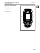
SK750/SK755 Operator’s Manual Overview - 2 Serial Number Location Serial Number Location Record serial numbers and date of purchase in spaces provided. Unit serial number is located as shown. t35om034w.
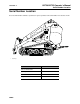
SK750/SK755 Operator’s Manual Overview - 3 Intended Use Intended Use The SK750/SK755 is a platform, rubber track mini skid steer unit designed for light-to medium-duty construction work. The SK750/SK755 has a quick attach mount plate which makes it easy for an operator to connect different attachments. The unit is designed for operation in temperatures typically experienced in earth moving and construction work environments. Provisions may be required to operate in extreme temperatures.
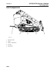
SK750/SK755 Operator’s Manual Overview - 4 Unit Components Unit Components 1 t35om001w.eps 1. Operator station 2. Tracks 3. Engine compartment 4. Lift arms 5.
SK750/SK755 Operator’s Manual Overview - 5 Operator Orientation Operator Orientation 1 1. Front of unit 2. Right side of unit 3. Rear of unit 4. Left side of unit 4 2 3 t35om002w.
Overview - 6 SK750/SK755 Operator’s Manual About This Manual About This Manual This manual contains information for the proper use of this machine. See the beige Operation Overview pages for basic operating procedures. Cross references such as “See page 50” will direct you to detailed procedures. Bulleted Lists Bulleted lists provide helpful or important information or contain procedures that do not have to be performed in a specific order.
SK750/SK755 Operator’s Manual Foreword - 7 Foreword This manual is an important part of your equipment. It provides safety information and operation instructions to help you use and maintain your Ditch Witch equipment. Read this manual before using your equipment. Keep it with the equipment at all times for future reference. If you sell your equipment, be sure to give this manual to the new owner. If you need a replacement copy, contact your Ditch Witch dealer.
Foreword - 8 SK750/SK755 Operator’s Manual SK750/755 Operator’s Manual Issue number 2.0 / OM-7/14 Part number 053-2570 Copyright 2012, 2014 by The Charles Machine Works, Inc. , Ditch Witch, CMW, and Roto Witch are registered trademarks of The Charles Machine Works, Inc.
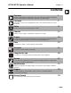
SK750/SK755 Operator’s Manual Contents - 9 Contents Overview 1 machine serial number, information about the type of work this machine is designed to perform, basic machine components, and how to use this manual Foreword 7 part number, revision level, and publication date of this manual, and factory contact information Safety 11 machine safety alerts and emergency procedures Controls 21 machine controls, gauges, and indicators and how to use them Prepare 29 procedures for inspecting and class
Contents - 10 CMW® SK750/SK755 Operator’s Manual
SK750/SK755 Operator’s Manual Safety - 11 Safety Chapter Contents Guidelines . . . . . . . . . . . . . . . . . . . . . . . . . . . . . . . . 12 Emergency Procedures . . . . . . . . . . . . . . . . . . . . . 13 • Electric Strike Description . . . . . . . . . . . . . . . . . . . . . . . . . . . . . . . . . . . .13 • If an Electric Line is Damaged . . . . . . . . . . . . . . . . . . . . . . . . . . . . . . . .14 • If a Gas Line is Damaged . . . . . . . . . . . . . . . . . . . . . . . . . . . . . . . . .
Safety - 12 SK750/SK755 Operator’s Manual Guidelines Guidelines Follow these guidelines before operating any jobsite equipment: • Complete proper training and read operator’s manual before using equipment. • Contact your local One-Call (811 in USA) or the One-Call referral number (888-258-0808 in USA and Canada) to have underground utilities located before digging. Also contact any utilities that do not participate in the One-Call service.
SK750/SK755 Operator’s Manual Safety - 13 Emergency Procedures Emergency Procedures Jobsite hazards could cause death or serious injury. Use correct equipment and work methods. Use and maintain proper safety equipment. 274-050 Before operating any equipment, review emergency procedures and check that all safety precautions have been taken. EMERGENCY SHUTDOWN - Turn ignition switch to stop position or push remote engine stop button (if equipped). Electric Strike Description Electric shock.
Safety - 14 SK750/SK755 Operator’s Manual Emergency Procedures If an Electric Line is Damaged If you suspect an electric line has been damaged and you are on tractor, DO NOT MOVE. Remain on tractor and take the following actions. The order and degree of action will depend upon the situation. • Warn people nearby that an electric strike has occurred. Instruct them to leave the area and contact utility. • Raise attachments and drive from immediate area. • Contact utility company to shut off power.
SK750/SK755 Operator’s Manual Safety - 15 Emergency Procedures If a Gas Line is Damaged Fire or explosion possible. Fumes could ignite and cause burns. No smoking, no flame, no spark. 275-419 (2P) Explosion possible. Serious injury or equipment damage could occur. Follow directions carefully. If you suspect a gas line has been damaged, take the following actions. The order and degree of action will depend on the situation. • Immediately shut off engine(s), if this can be done safely and quickly.
Safety - 16 SK750/SK755 Operator’s Manual Emergency Procedures If a Fiber Optic Cable is Damaged Do not look into cut ends of fiber optic or unidentified cable. Vision damage can occur. Contact utility company. If Machine Catches on Fire Perform emergency shutdown procedure and then take the following actions. The order and degree of action will depend on the situation. • Immediately move battery disconnect switch (if equipped and accessible) to disconnect position.
SK750/SK755 Operator’s Manual Safety - 17 Safety Alert Classifications Safety Alert Classifications These classifications and the icons defined on the following pages work together to alert you to situations which could be harmful to you, jobsite bystanders or your equipment. When you see these words and icons in the book or on the machine, carefully read and follow all instructions. YOUR SAFETY IS AT STAKE. Watch for the three safety alert levels: DANGER, WARNING and CAUTION.
SK750/SK755 Operator’s Manual Safety - 18 Machine Safety Alerts Machine Safety Alerts 1 2 Crushing weight. Place cylinder lock on extended cylinder and secure. 273-413 Read operator’s manual. Know how to use all controls. Your safety is at stake. 273-475 Lift point. See Transport chapter for more information.
SK750/SK755 Operator’s Manual Safety - 19 Machine Safety Alerts Tiedown location. See Transport chapter for more information. 274-318 4 Moving parts could cut off hand or foot. Stay away. 5 6 275-184 Crushing weight could cause death or serious injury. Stay away. 275-326 Hot parts may cause burns. Do not touch until cool 7 8 or wear gloves. 275-355 (2-P) Shut down engine before opening hood for servicing and maintaining machine.
Safety - 20 SK750/SK755 Operator’s Manual Machine Safety Alerts CMW®
SK750/SK755 Operator’s Manual Controls - 21 Gauges and Indicators Controls Gauges and Indicators 1 6 2 7 8 3 9 4 5 10 t35om003w.eps 1. Glow plug button 6. Ignition switch 2. Engine coolant temperature gauge 7. Hourmeter 3. Engine oil pressure indicator 8. Engine coolant temperature indicator 4. Hydraulic fluid temperature indicator 9. Glow plug indicator 5. Hydraulic fluid level sight glass 10.
SK750/SK755 Operator’s Manual Controls - 22 Gauges and Indicators Item Description Notes 1. Glow plug button To help start cold engine, turn ignition switch to first position. IMPORTANT: Press glow plug button according to temperatures below. Press glow plug button as directed in notes. • If ambient temperature is below 40° F (4° C), press and hold button for 5 seconds. • If ambient temperature is below 20° F (-7° C), press and hold button for 10 seconds.
SK750/SK755 Operator’s Manual Controls - 23 Gauges and Indicators Item Description Notes 6. Ignition switch To start engine, insert key and turn clockwise. IMPORTANT: • If engine does not start or stalls, turn key to STOP and then restart. • Do not allow starter motor to run continuously for more than 20 seconds. To stop engine, turn key counterclockwise. 7. Hourmeter Displays engine operating time. Use these times to schedule service. 8.
SK750/SK755 Operator’s Manual Controls - 24 Controls Controls 1 5 2 6 3 7 4 t35om004w.eps 1. Left track drive control or Track drive joystick (optional) 2. Right track drive control or Track drive joystick (optional) 3. Throttle 4. Parking brake lever CMW® 5. Lift arm control 6. Attachment drive control 7.
SK750/SK755 Operator’s Manual Controls - 25 Controls Item Description Notes 1. Left track drive control To move forward, push. 2. Right track drive control To turn right, move left control farther forward than right control. To move backward, pull. To go faster in either direction, move control farther from neutral position. To stop, move to neutral position. Track drive joystick (optional)l To move forward, push. To move backward, pull.
SK750/SK755 Operator’s Manual Controls - 26 Controls Item Description 4. Parking brake lever To engage, rotate lever counterclockwise. Notes To disengage, rotate lever clockwise. c00ic662w.eps 5. Lift arm control To move lift arms down, push. To float, push forward to end. IMPORTANT: Exercise caution when lifting loads. See page 72 for operating capacities. To move lift arms up, pull. To curl attachment up, move to left. To curl attachment down, move to right. 6.
SK750/SK755 Operator’s Manual Controls - 27 Engine Compartment Engine Compartment 1 2 t35om016w.eps 1. Hydraulic Fluid Bypass 2. Auxiliary outlet Item Description Notes 1. Hydraulic Fluid Bypass To open bypass valve, pull and rotate knob until it seats in the open position. IMPORTANT: Start engine and run five minutes to warm hydraulic fluid. c00ic663w.eps 2. Auxiliary power outlet • Use the hydraulic fluid bypass to assist starting a cold engine.
SK750/SK755 Operator’s Manual Controls - 28 Tool Carrier Tool Carrier 1. Level indicator Item Description Notes 1. Level indicator To level bucket, adjust bucket position until indicator is at top of sleeve. To level other attachments, adjust attachment position until it is level. Mark indicator position on sleeve. Use mark to indicate level with that attachment.
SK750/SK755 Operator’s Manual Prepare - 29 Prepare Chapter Contents Gather Information . . . . . . . . . . . . . . . . . . . . . . . . . 30 • All Jobs . . . . . . . . . . . . . . . . . . . . . . . . . . . . . . . . . . . . . . . . . . . . . . . . . .30 • Ground-Penetrating Jobs . . . . . . . . . . . . . . . . . . . . . . . . . . . . . . . . . . . .30 • Above-Ground Jobs . . . . . . . . . . . . . . . . . . . . . . . . . . . . . . . . . . . . . . . .30 Inspect Site . . . . . . . . . . . . . . . . . .
Prepare - 30 SK750/SK755 Operator’s Manual Gather Information Gather Information A successful job begins before you start working. The first step in planning is reviewing information already available about the job and jobsite. All Jobs Review Job Plan Review blueprints or other plans. Check for information about existing or planned structures, elevations, or proposed work that may be taking place at the same time.
SK750/SK755 Operator’s Manual Prepare - 31 Inspect Site Inspect Site Inspect jobsite before transporting equipment. Check for the following: • changes in elevation such as hills or other open trenches • obstacles such as buildings, railroad crossings, or streams • signs of utilities (See “Inspect Jobsite” on page 32.) • traffic • access • soil type and condition Identify Hazards Identify safety hazards and classify jobsite if attachment will penetrate ground.
Prepare - 32 SK750/SK755 Operator’s Manual Classify Jobsite Classify Jobsite Inspect Jobsite • Inspect jobsite and perimeter for evidence of underground hazards, such as: – “buried utility” notices – utility facilities without overhead lines – gas or water meters – junction boxes – drop boxes – light poles – manhole covers – sunken ground • Follow U.S. Department of Labor regulations on excavating and trenching (Part 1926, Subpart P) and other similar regulations.
SK750/SK755 Operator’s Manual Prepare - 33 Classify Jobsite Apply Precautions Once classified, precautions appropriate for jobsite must be taken. Electric Jobsite Precautions Use one or both of these methods. • Expose line by careful hand digging or soft excavation. • Have service shut down while work is in progress. Have electric company test lines before returning them to service.
Prepare - 34 SK750/SK755 Operator’s Manual Check Supplies and Prepare Equipment Check Supplies and Prepare Equipment Supplies • fuel NOTICE: Use low sulfur or ultra low sulfur fuel only. • keys • lubricants • personal protective equipment, such as hard hat and safety glasses Fluid Levels • fuel NOTICE: Use low sulfur or ultra low sulfur fuel only. • hydraulic fluid • battery charge • engine oil Condition and Function • parking brake pins (See “Check Brake Operation” on page 57.
SK750/SK755 Operator’s Manual Prepare - 35 Connect Attachment Connect Attachment NOTICE: Use only Ditch Witch-approved attachments. Attachments can change the stability and operating characteristics of the unit. Attachment IMPORTANT: Before connecting attachment to unit, ensure that mount and receiver plates are free of dirt and debris. 1. Position attachment on level surface with enough space behind it to accommodate unit. 2.
SK750/SK755 Operator’s Manual Prepare - 36 Connect Attachment Hydraulic Hoses If attachment requires hydraulic power for operation, connect hydraulic hoses. Pressurized fluid or air could pierce skin and cause injury or death. Stay away. To help avoid injury: • Escaping pressurized fluid can cause injury or pierce skin and poison. • Before disconnecting a hydraulic line, turn engine off and operate all controls to relieve pressure. Lower, block, or support any raised component with a hoist.
SK750/SK755 Operator’s Manual Drive - 37 Drive Chapter Contents Start Unit . . . . . . . . . . . . . . . . . . . . . . . . . . . . . . . . . 38 Drive . . . . . . . . . . . . . . . . . . . . . . . . . . . . . . . . . . . . . 38 Shut Down . . . . . . . . . . . . . . . . . . . . . . . . . . . . . . . .
SK750/SK755 Operator’s Manual Drive - 38 Start Unit Start Unit 1. Ensure all controls are in neutral. 2. If necessary, use glow plugs and/or hydraulic fluid bypass control to warm cold engine. See “Hydraulic Fluid Bypass” on page 27. 3. Move throttle to half open. 4. Turn ignition switch to start position and release when engine starts. EMERGENCY SHUTDOWN: Turn ignition switch to STOP. Drive General Operation Tipover possible. Machine can tip over and crush you.
SK750/SK755 Operator’s Manual Drive - 39 Drive Safe Slope Operation Tipover possible. Machine can tip over and crush you. To help avoid injury: • Always operate with heavy end uphill. • Always carry load low. High load can cause tipping, loss of load or loss of visibility. • Drive cautiously at all times. • Never jerk control levers. Use a steady even motion.
Drive - 40 SK750/SK755 Operator’s Manual Shut Down Shut Down 1. Lower lift arms to ground. 2. Move all controls to neutral position. 3. Apply parking brake. 4. Run engine at low idle for five minutes to cool. NOTICE: Failure to allow engine to cool before shutdown may damage turbocharger. 5. Turn ignition switch to STOP. 6. Remove key.
SK750/SK755 Operator’s Manual Transport - 41 Transport Chapter Contents Lift . . . . . . . . . . . . . . . . . . . . . . . . . . . . . . . . . . . . . . 42 • Points . . . . . . . . . . . . . . . . . . . . . . . . . . . . . . . . . . . . . . . . . . . . . . . . . . .42 • Procedure . . . . . . . . . . . . . . . . . . . . . . . . . . . . . . . . . . . . . . . . . . . . . . . .43 Haul . . . . . . . . . . . . . . . . . . . . . . . . . . . . . . . . . . . . . 44 • Load . . . . . . . . . . . . . . . . . . .
Transport - 42 SK750/SK755 Operator’s Manual Lift Lift Crushing weight. If load falls or moves it could kill or crush you. Use proper procedures and equipment or stay away. To help avoid injury: Only lift unit without attachment installed. Points Lifting points are identified by lifting decals. Lifting at other points is unsafe and can damage machinery.
SK750/SK755 Operator’s Manual Transport - 43 Lift Procedure Use a hoist capable of supporting the equipment's size and weight. See “Specifications” on page 71 or measure and weigh equipment before lifting. Use one of the methods below: • Use two points nearest operator station. IMPORTANT: Front of unit will be lower than rear of unit when using only two lift points. • Use three lift points as shown. t35om022w.
SK750/SK755 Operator’s Manual Transport - 44 Haul Haul Load Crushing weight. If load falls or moves it could kill or crush you. Use proper procedures and equipment or stay away. To help avoid injury: • Load and unload trailer on level ground. • Incorrect loading can cause trailer swaying. • Attach trailer to vehicle before loading or unloading. • Only operate unit from operator platform.
SK750/SK755 Operator’s Manual Transport - 45 Haul Tie Down Points Tiedown points are identified by tiedown decals. Securing to truck or trailer at other points is unsafe and can damage machinery. Procedure Loop tiedowns around unit at tiedown points. Make sure tiedowns are tight before transporting. t35om005w.
SK750/SK755 Operator’s Manual Transport - 46 Haul Unload Crushing weight. If load falls or moves it could kill or crush you. Use proper procedures and equipment or stay away. To help avoid injury: • Load and unload trailer on level ground. • Attach trailer to vehicle before loading or unloading. • Only operate unit from operator platform. • If unloading from tilt-bed trailer, be prepared for trailer to tilt. 1. Prepare trailer and ramps for unloading. 2. Remove tiedowns. 3.
SK750/SK755 Operator’s Manual Transport - 47 Tow Tow Read operator’s manual. Know how to use all controls before operating machine. When you see this sign on the machine or in the manual, read it and use caution. Your safety is at stake. Under normal conditions, unit should not be towed. If unit breaks down and towing is necessary: t35om007w.eps t35om006w.eps rear tow point • attach chains to tow points facing towing vehicle • tow for short distances at less than 1 mph (1.
Transport - 48 SK750/SK755 Operator’s Manual Tow Prepare Unit for Towing 1. Block tracks. 2. Engage parking brake (shown). t35om008w.eps 3. Loosen bypass valves (shown) three turns. IMPORTANT: Open bypass valves in both front and rear pumps. NOTICE: When bypass valves are open, unit has no brakes. t35om012w.eps Return Unit to Normal Operation 1. Tighten bypass valves and tighten locknut to 15-18 ft•lb (20-25 N•m). IMPORTANT: Close bypass valve in both front and rear pumps. 2. Disengage parking brake.
SK750/SK755 Operator’s Manual Complete the Job - 49 Complete the Job Chapter Contents Rinse Equipment . . . . . . . . . . . . . . . . . . . . . . . . . . 50 Disconnect Attachment . . . . . . . . . . . . . . . . . . . . . 50 Stow Tools . . . . . . . . . . . . . . . . . . . . . . . . . . . . . . .
Complete the Job - 50 SK750/SK755 Operator’s Manual Rinse Equipment Rinse Equipment 1. Spray water onto equipment to remove dirt and mud. NOTICE: Do not spray water onto operator’s console. Electrical components could be damaged. Wipe down instead. 2. Open hood and allow unit to cool. Remove debris from inside of unit. 3. Remove mud from track sprockets. 4. Wash undercarriage. Pay special attention to brake pin area. Disconnect Attachment 1. Lower attachment to the ground. 2. Turn off engine. 3.
SK750/SK755 Operator’s Manual Service - 51 Service Chapter Contents Precautions . . . . . . . . . . . . . . . . . . . . . . . . . . . . . . 52 Overview . . . . . . . . . . . . . . . . . . . . . . . . . . . . . . . . . 53 Recommended Lubricants/Service Key . . . . . . . . 53 Engine Oil Temperature Chart . . . . . . . . . . . . . . . 54 10 Hour . . . . . . . . . . . . . . . . . . . . . . . . . . . . . . . . . . 56 50 Hour . . . . . . . . . . . . . . . . . . . . . . . . . . . . . . . . . . 60 200 Hour. . . .
SK750/SK755 Operator’s Manual Service - 52 Precautions Precautions Read operator’s manual. Know how to use all controls. Your safety is at stake. 273-475 To help avoid injury: • Unless otherwise instructed, all service should be performed with engine off. • Before servicing equipment, lower unstowed attachments to ground. Working Under Raised Lift Arms Crushing weight. Place cylinder lock on extended cylinder and secure. 273-231 Use safety supports as indicated when working under raised lift arms.
SK750/SK755 Operator’s Manual Service - 53 Overview Overview t35om035w.
SK750/SK755 Operator’s Manual Service - 54 Engine Oil Temperature Chart Engine Oil Temperature Chart Temperature range anticipated before next oil change For more information on engine lubrication and maintenance, see your engine manual. Approved Coolants This unit was filled with John Deere Cool-Gard coolant before shipment from factory.
SK750/SK755 Operator’s Manual Service - 55 Engine Oil Temperature Chart Approved Fuel The engine is this unit is designed to run on diesel fuel. Use only high-quality fuel meeting ASTM D975 No. 2D, EN590, or equivalent. At temperatures below 32°F (0°C), winter fuel blends are acceptable. See engine operation manual for more information. IMPORTANT: • For machines operated in the U.S.: The engine in this product is certified to operate on low sulfur diesel fuel (LSD) with a sulfur content of 500 ppm (0.
SK750/SK755 Operator’s Manual Service - 56 Startup/10 Hour Startup/10 Hour Location Task Notes Check engine oil level DEO Check engine air filter service indicator Check engine coolant level DEAC Check hydraulic fluid level THF Check brake operation Check track tension Check lug nut torque 88-95 ft•lb (108-129 N•m) Check hydraulic hoses Check Engine Oil Level Check engine oil level at dipstick opening (1) at startup and every 10 hours. Oil level should be at top of marking.
SK750/SK755 Operator’s Manual Service - 57 Startup/10 Hour Check Hydraulic Fluid Level Check hydraulic fluid level at startup and every 10 hours. Maintain fluid level at halfway point on sight glass (2), when engine is off, cylinders are fully retracted, and fluid is cool. If low, add THF at fill (1). 1 2 t35om013w.eps Check Brake Operation Check brake operation at startup and every 10 hours or more often when conditions warrant.
Service - 58 SK750/SK755 Operator’s Manual Startup/10 Hour Check Track Tension Check track tension at startup and every 10 hours and adjust as needed. Track is correctly tensioned when measurement between track and straight edges (2) is 1/2 in (13 mm). 1 To adjust: 1. Park machine on smooth flat surface. 2. Lay straight edge on top of track, spanning from sprocket to front idler roller. 3. Clean track cylinder zerk (1).
SK750/SK755 Operator’s Manual Service - 59 Startup/10 Hour Check Hydraulic Hoses Pressurized fluid or air could pierce skin and cause severe injury. Refer to operator’s manual for proper use. 270-6035 To help avoid injury: • Before disconnecting a hydraulic line, turn engine off and operate all controls to relieve pressure. Lower, block, or support any raised component with a hoist. Cover connection with heavy cloth and loosen connector nut slightly to relieve residual pressure.
SK750/SK755 Operator’s Manual Service - 60 50 Hour 50 Hour Location Task Notes Change engine oil and filter initial service Check fan belt tension and damage 1/4-1/3” (7-9 mm) Change hydraulic fluid filter initial Check fuel hose and clamp band Check radiator/hydraulic fluid cooler for dirt and debris Check lug nut torque 88-95 ft•lb (108-129 N•m) Change Engine Oil and Filter (Initial) Change engine oil after 50 hours. Drain oil (1) and add 4.2 qt (4 L) of DEO at fill (2).
SK750/SK755 Operator’s Manual Service - 61 50 Hour Change Hydraulic Filter (initial) Change hydraulic filter after 50 hours. t35om019w.eps Check Fan Belt for Tension and Damage Check belt tension every 50 hours. Belt is properly tensioned when it moves about 1/4-3/8” (7-9 mm) when pushed at the long span. Replace the belt when it is worn and sinks into the pulley groove. Adjust Tension 1. Loosen two alternator bolts (shown). 2. Adjust position as needed. 3. Tighten bolts. 4. Check tension.
Service - 62 SK750/SK755 Operator’s Manual 50 Hour Check Radiator/Fluid Cooler Check radiator/hydraulic fluid cooler for dirt, grass, and other foreign matter every 50 hours. Clean out with compressed air or spray wash if required. Be careful not to damage fins with highpressure air or water. Check more often if operating in dusty or grassy conditions. Check radiator hoses for wear. Check hose clamps for proper tightness. t35om020w.
SK750/SK755 Operator’s Manual Service - 63 200 Hour 200 Hour Location Task Notes Change engine oil and filter 4.2 qt (4 L) DEO Check intake air line 1/4-1/3” (7-9 mm) Change hydraulic filter Check lug nut torque 88-95 ft•lb (108-129 N•m) Change Engine Oil and Filter Change engine oil and filter every 200 hours. Drain oil, change filter (shown) and add 4.2 qt (4 L) of DEO at fill. See page 60. IMPORTANT: Use oil specified in “Engine Oil Temperature Chart” on page 54.
Service - 64 SK750/SK755 Operator’s Manual 200 Hour Change Hydraulic Filter Change hydraulic filter every 200 hours. t35om019w.eps Check Lug Nut Torque Check lug nut torque at initial intervals and every 200 hours thereafter. Tighten to 88-95 ft•lb (108129 N•m) as needed. t35om036w.
SK750/SK755 Operator’s Manual Service - 65 500 Hour 500 Hour Location Task Notes Change fuel filters Change hydraulic fluid and filter Change Fuel Filters Change filters every 500 hours. If you refuel from cans, replace filters more often. The canister filter is located in the engine compartment. The inline filter is located under the control console. See parts manual or contact your Ditch Witch dealer for correct replacement filter. t35om028w.eps t35om030w.
SK750/SK755 Operator’s Manual Service - 66 2000 Hour Change Hydraulic Fluid and Filter Change hydraulic fluid and filter every 500 hours. Change every 250 hours if jobsite temperature exceeds 100°F (38°C) more than 50% of the time. 1. Remove drain plug (3). 1 2 2. Drain fluid and replace plug. 3. Change filter. See page 64. 4. Add THF at fill (1) until fluid level is at halfway point on sight glass (2). Capacity is 9.2 gal (35 L). 3 t35om029w.
SK750/SK755 Operator’s Manual Service - 67 As Needed As Needed Location Task Notes Change air filter Check battery Charge battery Change Air Filter Change air filter when red band on indicator (1) is visible. Replace safety element (4) every third change of primary filter (3) or any time primary element has become damaged. 3 1 1. Open air filter housing at latches (2). 2 2. Remove primary element (3). 3. Wipe inside of housing and end cup (2). 4. Insert new primary element. 5.
SK750/SK755 Operator’s Manual Service - 68 As Needed Check Battery Check battery as needed. Keep battery clean and terminals free of corrosion. To clean: 1. Turn battery disconnect switch, if equipped, to the off position. 2. Ensure that no ignition sources are near batteries. 3. Loosen and remove battery cable clamps carefully, negative (-) cable first. 4. Clean cable clamps and terminals to remove dull glaze. 5. Check for signs of internal corrosion in cables. 6.
SK750/SK755 Operator’s Manual Service - 69 As Needed Charge Battery Explosion possible. Serious injury or equipment damage could occur. Follow directions carefully. To help avoid injury: • Use a single 12V maximum source for charging. Do not connect to rapid chargers or dual batteries. • Use caution and wear personal protective equipment such as safety eyewear, when charging or cleaning battery. • Keep sparks, flames, and any ignition source away from batteries at all times.
Service - 70 SK750/SK755 Operator’s Manual As Needed Charging Procedure (Engine Off) 1. Park service vehicle close to disabled equipment but do not allow vehicles to touch. Engage parking brake in both vehicles. 2. Turn the ignition switch to the OFF position in both vehicles, and turn off all electrical loads. Disconnect the machine controller. 3. Inspect battery in disabled vehicle (B) for signs of cracking, bulging, leaking, or other damage.
SK750/SK755 Operator’s Manual Specifications - 71 SK750/SK755 Basic Unit Specifications SK750/SK755 Basic Unit L H2 H A2 L2 W Dimensions U.S.
Specifications - 72 SK750/SK755 Operator’s Manual SK750/SK755 Basic Unit Dimensions U.S. Metric Bucket rollback angle, ground level 25° 25° Bucket rollback angle, full height 90° 90° Dump angle, standard bucket at max dump height 35° 35° Bucket width, max 44 in 1120 mm Bucket width, min 36 in 915 mm Swing radius, max, with standard bucket 65 in 1650 mm Swing radius, no attachment 44 in 1120 mm Rear overhang, max 29 in 735 mm Performance U.S.
SK750/SK755 Operator’s Manual Specifications - 73 SK750 Power Specifications SK750 Power Specifications Power U.S. Metric Engine: Kubota D1105, diesel, EPA Tier 4, EU Stage IIIa Number of cylinders 3 Displacement 68.5 in3 1.12 L Bore 3.07 in 78 mm Stroke 3.09 in 78.4 mm Manufacturer’s gross power rating (per SAE J1955) 23.1 hp 17.2 kW Estimated net power rating (per SAE 1348) 31.5 hp 23.5 kW Rated engine speed 3000 rpm 3000 rpm Hydraulic System U.S. Metric Flow rate (pump 1) 6.
SK750/SK755 Operator’s Manual Specifications - 74 SK755 Power Specifications SK755 Power Specifications Power U.S. Metric Engine: Kubota D1105-T, diesel, EPA Tier 4, EU Stage IIIa Number of cylinders 3 Displacement 68.5 in3 1.12 L Bore 3.07 in 78 mm Stroke 3.09 in 78.4 mm Manufacturer’s gross power rating (per SAE J1955) 32.8 hp 24.5 kW Estimated net power rating (per SAE 1348) 31.5 hp 23.
SK750/SK755 Operator’s Manual Support - 75 Procedure Support Procedure Notify your dealer immediately of any malfunction or failure of Ditch Witch® equipment. Always give model, serial number, and approximate date of your equipment purchase. This information should be recorded and placed on file by the owner at the time of purchase. Return damaged parts to dealer for inspection and warranty consideration if in warranty time frame.
SK750/SK755 Operator’s Manual Warranty - 76 Warranty Ditch Witch® Equipment and Replacement Parts Limited Warranty Policy Subject to the limitation and exclusions herein, free replacement parts will be provided at any authorized Ditch Witch dealership for any Ditch Witch equipment or parts manufactured by The Charles Machine Works, Inc. (CMW) that fail due to a defect in material or workmanship within one (1) year of first commercial use.
SK750/SK755 Operator’s Manual Service Record - 79 Service Record Service Performed Date Hours CMW®
Service Record - 80 Service Performed CMW® SK750/SK755 Operator’s Manual Date Hours