RT12/RT16/RT20/RT24 Operator’s Manual CMW® Issue 1.
RT12/RT16/RT20/RT24 Operator’s Manual Overview - 1 Overview Chapter Contents Serial Number Location . . . . . . . . . . . . . . . . . . . . . . 2 Intended Use . . . . . . . . . . . . . . . . . . . . . . . . . . . . . . . 3 Equipment Modification . . . . . . . . . . . . . . . . . . . . . . 3 Unit Components . . . . . . . . . . . . . . . . . . . . . . . . . . . 3 Operator Orientation. . . . . . . . . . . . . . . . . . . . . . . . . 4 About This Manual . . . . . . . . . . . . . . . . . . . . . . . . . .
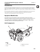
RT12/RT16/RT20/RT24 Operator’s Manual Overview - 2 Serial Number Location Serial Number Location Record serial numbers and date of purchase in spaces provided. Trencher serial number is located as shown.
RT12/RT16/RT20/RT24 Operator’s Manual Overview - 3 Intended Use Intended Use The RT12, RT16, RT20, and RT24 pedestrian trenchers are designed to install buried cable and pipe to depths of 48” (1220 mm) and widths of 8” (200 mm). These units are intended for operation in ambient temperatures from 20° to 115°F (-7° to 46°C). Use in any other way is considered contrary to the intended use. RT12, RT16, RT20, and RT24 units should be used with genuine Ditch Witch chain, teeth, and sprockets.
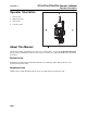
Overview - 4 RT12/RT16/RT20/RT24 Operator’s Manual Operator Orientation Operator Orientation 1. Front of unit 2. Right side of unit 3. Rear of unit 4. Left side of unit About This Manual This manual contains information for the proper use of this machine. See the beige Operation Overview pages for basic operating procedures. Cross references such as “See page 50” will direct you to detailed procedures.
RT12/RT16/RT20/RT24 Operator’s Manual Foreword - 5 Foreword This manual is an important part of your equipment. It provides safety information and operation instructions to help you use and maintain your Ditch Witch equipment. Read this manual before using your equipment. Keep it with the equipment at all times for future reference. If you sell your equipment, be sure to give this manual to the new owner. If you need a replacement copy, contact your Ditch Witch dealer.
Foreword - 6 RT12/RT16/RT20/RT24 Operator’s Manual RT12/RT16/RT20/RT24 Operator’s Manual Issue number 1.0/OM-12/11 Part number 053-2439 Copyright 2011 by The Charles Machine Works, Inc. , Ditch Witch, CMW, and Roto Witch are registered trademarks of The Charles Machine Works, Inc.
RT12/RT16/RT20/RT24 Operator’s Manual Contents - 7 Contents Overview 1 machine serial number, information about the type of work this machine is designed to perform, basic machine components, and how to use this manual Foreword 5 part number, revision level, and publication date of this manual, and factory contact information Safety 9 machine safety alerts and emergency procedures Controls 21 machine controls, gauges, and indicators and how to use them Prepare 31 procedures for inspecting an
Contents - 8 RT12/RT16/RT20/RT24 Operator’s Manual Specifications 95 machine specifications including weights, measurements, power ratings, and fluid capacities Support 109 the warranty policy for this machine, and procedures for obtaining warranty consideration and training Service Record a record of major service performed on the machine CMW 113
RT12/RT16/RT20/RT24 Operator’s Manual Safety - 9 Safety Chapter Contents Guidelines . . . . . . . . . . . . . . . . . . . . . . . . . . . . . . . . 10 Safety Alert Classifications . . . . . . . . . . . . . . . . . . 11 Safety Alerts . . . . . . . . . . . . . . . . . . . . . . . . . . . . . . 12 Emergency Procedures . . . . . . . . . . . . . . . . . . . . . 15 • Electric Strike Description . . . . . . . . . . . . . . . . . . . . . . . . . . . . . . . . . . . 15 • If an Electric Line is Damaged . . . . .
Safety - 10 RT12/RT16/RT20/RT24 Operator’s Manual Guidelines Guidelines Follow these guidelines before operating any jobsite equipment: • Complete proper training and read operator’s manual before using equipment. • Contact your local One-Call (811 in USA) or the One-Call referral number (888-258-0808 in USA and Canada) to have underground utilities located before digging. Also contact any utilities that do not participate in the One-Call service.
RT12/RT16/RT20/RT24 Operator’s Manual Safety - 11 Safety Alert Classifications Safety Alert Classifications These classifications and the icons defined on the following pages work together to alert you to situations which could be harmful to you, jobsite bystanders or your equipment. When you see these words and icons in the book or on the machine, carefully read and follow all instructions. YOUR SAFETY IS AT STAKE. Watch for the three safety alert levels: DANGER, WARNING and CAUTION.
RT12/RT16/RT20/RT24 Operator’s Manual Safety - 12 Safety Alerts Safety Alerts Moving digging teeth will kill you or cut off arm or leg. Stay away. Turning shaft will kill you or crush arm or leg. Stay away. Electric shock. Contacting electric lines will cause death or serious injury. Know location of lines and stay away. Deadly gases. Lack of oxygen or presence of gas will cause sickness or death. Provide ventilation. Jobsite hazards could cause death or serious injury.
RT12/RT16/RT20/RT24 Operator’s Manual Safety - 13 Safety Alerts Explosion possible. Serious injury or equipment damage could occur. Follow directions carefully. Incorrect procedures could result in death, injury, or property damage. Learn to use equipment correctly. Improper control function could cause death or serious injury. If control does not work as described in instructions, stop machine and have it serviced. Looking into fiber optic cable could result in permanent vision damage.
RT12/RT16/RT20/RT24 Operator’s Manual Safety - 14 Safety Alerts Hot pressurized cooling system fluid could cause serious burns. Allow to cool before servicing. Flying objects may cause injury. Wear hard hat and safety glasses. Hot parts may cause burns. Do not touch until cool. Exposure to high noise levels may cause hearing loss. Wear hearing protection. Fall possible. Slips or trips may result in injury. Keep area clean. Battery acid may cause burns. Avoid contact.
RT12/RT16/RT20/RT24 Operator’s Manual Safety - 15 Emergency Procedures Emergency Procedures Jobsite hazards could cause death or serious injury. Use correct equipment and work methods. Use and maintain proper safety equipment. Before operating any equipment, review emergency procedures and check that all safety precautions have been taken. EMERGENCY SHUTDOWN - Release all controls and turn ignition switch to STOP. Electric Strike Description Electric shock.
RT12/RT16/RT20/RT24 Operator’s Manual Safety - 16 Emergency Procedures If an Electric Line is Damaged If you suspect an electric line has been damaged and you are near pedestrian unit, DO NOT MOVE and do not touch unit. Take the following actions. The order and degree of action will depend upon the situation. • Warn people nearby that an electric strike has occurred. Instruct them to leave the area and contact utility. • Do not allow anyone into area until given permission by utility company.
RT12/RT16/RT20/RT24 Operator’s Manual Safety - 17 Emergency Procedures If a Fiber Optic Cable is Damaged Do not look into cut ends of fiber optic or unidentified cable. Vision damage can occur. If Machine Catches on Fire Perform emergency shutdown procedure and then take the following actions. The order and degree of action will depend on the situation. • Immediately move battery disconnect switch (if equipped) to disconnect position.
Safety - 18 RT12/RT16/RT20/RT24 Operator’s Manual Emergency Procedures CMW
RT12/RT16/RT20/RT24 Operator’s Manual Operation Overview - 19 Operation Overview Chapter Contents Planning. . . . . . . . . . . . . . . . . . . . . . . . . . . . . . . . . . 20 Trenching. . . . . . . . . . . . . . . . . . . . . . . . . . . . . . . . . 20 Leaving Jobsite. . . . . . . . . . . . . . . . . . . . . . . . . . . .
Operation Overview - 20 RT12/RT16/RT20/RT24 Operator’s Manual Planning Planning 1. Gather information about jobsite. See page 31. 2. Inspect jobsite. See page 33. 3. Classify jobsite. See page 34. 4. Select best chain type and tooth pattern for your application. See page 62. 5. Consider optional equipment, if necessary. See page 64. 6. Check supplies and prepare equipment. See page 36. 7. Load unit onto trailer. See page 43. Trenching 1. Unload unit from trailer. See page 46. 2.
RT12/RT16/RT20/RT24 Operator’s Manual Controls - 21 Controls Chapter Contents Control Console . . . . . . . . . . . . . . . . . . . . . . . . . . . 22 RT12 Engine Controls . . . . . . . . . . . . . . . . . . . . . . 26 RT16 Engine Controls . . . . . . . . . . . . . . . . . . . . . . 27 RT20 and RT24 Engine Controls . . . . . . . . . . . . . .
Controls - 22 RT12/RT16/RT20/RT24 Operator’s Manual Control Console Control Console 1. Digging chain/Roto Witch® control 6. Hourmeter/tachometer (RT16 option) 2. Selector valve control (Roto Witch® option) 6B. Hourmeter (RT 12 option) 3. Boom lift control 4. Speed/direction controls 5. Parking brake lever CMW 7. Ignition Switch (RT12) 8.
RT12/RT16/RT20/RT24 Operator’s Manual Controls - 23 Control Console Item Description Notes 1. Digging chain control To start digging chain, pull toward operator, then push down to dig position. NOTICE: Trenching movement is always backward (toward you). To stop digging chain, release control. To dislodge a rock or other obstruction, pull up on control to reverse chain. IMPORTANT: This control changes function when equipped with optional Roto Witch. NOTICE: To dislodge obstructions, reverse chain.
Controls - 24 RT12/RT16/RT20/RT24 Operator’s Manual Control Console Item Description Notes 4. Speed/direction controls To drive straight forward, push BOTH controls slowly forward. NOTICE: Trenching movement is always backward (toward you). To drive straight in reverse, pull BOTH controls slowly rearward. To turn left, move RIGHT speed/direction control for forward or reverse. To turn right, move LEFT speed/direction control for forward or reverse.
RT12/RT16/RT20/RT24 Operator’s Manual Controls - 25 Control Console Item Description Notes 6. Hourmeter/tachometer (RT16 option) Displays engine operating time and engine speed. Use engine operating times to schedule service. 6B. (RT12 option) c00ic259h.eps 7. Ignition switch (RT12) To start engine, turn key all the way clockwise. Release key as engine starts. To stop engine, turn key counterclockwise. 8. Throttle control (RT12) To increase engine speed, press bottom.
RT12/RT16/RT20/RT24 Operator’s Manual Controls - 26 RT12 Engine Controls RT12 Engine Controls 1 t27om070h.eps 1. Fuel shut-off valve Item Description Notes 1. Fuel shut-off valve To stop fuel flow from fuel tank to engine, slide lever away from engine. Close valve when transporting unit to or from jobsite, or whenever machine is parked. To allow fuel flow, slide lever toward engine.
RT12/RT16/RT20/RT24 Operator’s Manual Controls - 27 RT16 Engine Controls RT16 Engine Controls 1. Throttle control 3. Ignition switch 2. Choke control 4. Fuel shut-off valve Item Description 1. Throttle control To increase engine speed, pull up. Notes To decrease engine speed, push down. c00ic243h.
Controls - 28 RT12/RT16/RT20/RT24 Operator’s Manual RT16 Engine Controls Item Description Notes 2. Choke control To close choke valve, pull choke control. This valve can be closed to enrich air/fuel mixture and help start cold engine. Open choke valve after engine runs for a few seconds. 3. Ignition switch To start engine, turn key all the way clockwise. Release key as engine starts. To stop engine, turn key counterclockwise. 4.
RT12/RT16/RT20/RT24 Operator’s Manual Controls - 29 RT20/RT24 Engine Controls RT20/RT24 Engine Controls 1. Throttle control 4. Oil pressure indicator 2. Choke control 5. Hourmeter 3. Ignition switch Item Description 1. Throttle control To increase engine speed, pull up. Notes To decrease engine speed, push down.
Controls - 30 RT12/RT16/RT20/RT24 Operator’s Manual RT20/RT24 Engine Controls Item Description Notes 2. Choke control To close choke valve, pull choke control. This valve can be closed to enrich air/fuel mixture and help start cold engine. Open choke valve after engine runs for a few seconds. 3. Ignition switch To start engine, turn key all the way clockwise. Release key as engine starts. To stop engine, turn key counterclockwise. 4. Oil alert Indicator Lights when oil level is too low.
RT12/RT16/RT20/RT24 Operator’s Manual Prepare - 31 Prepare Chapter Contents Gather Information . . . . . . . . . . . . . . . . . . . . . . . . . 32 • Review Job Plan . . . . . . . . . . . . . . . . . . . . . . . . . . . . . . . . . . . . . . . . . . 32 • Notify One-Call Services . . . . . . . . . . . . . . . . . . . . . . . . . . . . . . . . . . . . 32 • Arrange for Traffic Control. . . . . . . . . . . . . . . . . . . . . . . . . . . . . . . . . . . 32 • Plan for Emergency Services . . . . . . . .
Prepare - 32 RT12/RT16/RT20/RT24 Operator’s Manual Gather Information Gather Information A successful job begins before you dig. The first step in planning is reviewing information already available about the job and jobsite. Review Job Plan Review blueprints or other plans. Check for information about existing or planned structures, elevations, or proposed work that may be taking place at the same time.
RT12/RT16/RT20/RT24 Operator’s Manual Prepare - 33 Inspect Site Inspect Site Inspect jobsite before transporting equipment. Check for the following: • changes in elevation such as hills or other open trenches • obstacles such as buildings, railroad crossings, or streams • signs of utilities (See “Inspect Jobsite” on page 34.) • traffic • access • soil type and condition Identify Hazards Identify safety hazards and classify jobsite. See “Classify Jobsite” on page 34.
Prepare - 34 RT12/RT16/RT20/RT24 Operator’s Manual Classify Jobsite Classify Jobsite Inspect Jobsite • Follow U.S. Department of Labor regulations on excavating and trenching (Part 1926, Subpart P) and other similar regulations. • Contact your local One-Call (811 in USA) or the One-Call referral number (888-258-0808 in USA and Canada) to have underground utilities located before digging. Also contact any utilities that do not participate in the One-Call service.
RT12/RT16/RT20/RT24 Operator’s Manual Prepare - 35 Classify Jobsite Apply Precautions Once classified, precautions appropriate for jobsite must be taken. Electric Jobsite Precautions Use one or both of these methods. • Expose line by careful hand digging or soft excavation. • Have service shut down while work is in progress. Have electric company test lines before returning them to service.
Prepare - 36 RT12/RT16/RT20/RT24 Operator’s Manual Check Supplies and Prepare Equipment Check Supplies and Prepare Equipment Supplies • fuel • keys • personal protective equipment, such as hard hat and safety glasses Fluid Levels • fuel • hydraulic fluid (SAE15W40) • battery charge • engine oil Condition and Function • digging chain and teeth • filters (air, oil, hydraulic, and fuel if equipped) • tires and tracks • pumps and motors • hoses and valves • signs, guards, and shields
RT12/RT16/RT20/RT24 Operator’s Manual Drive - 37 Drive Chapter Contents Start Unit . . . . . . . . . . . . . . . . . . . . . . . . . . . . . . . . . 38 Drive . . . . . . . . . . . . . . . . . . . . . . . . . . . . . . . . . . . . . 39 Shut Down . . . . . . . . . . . . . . . . . . . . . . . . . . . . . . . .
RT12/RT16/RT20/RT24 Operator’s Manual Drive - 38 Start Unit Start Unit 1. Check that all controls are in neutral. 2. If necessary, use choke control to start cold engine. Explosion possible. Using starting fluids will cause ignition in the intake manifold. 3. Move throttle to 1/4 open. RT12: Set throttle switch to low. 4. Turn ignition switch to START position to crank engine. 5. Release key when engine starts.
RT12/RT16/RT20/RT24 Operator’s Manual Drive - 39 Drive Drive NOTICE: Keep digging boom low when operating on a slope or transporting. Drive slowly and cautiously at all times. 1. Disengage parking brake. Improper control function could cause death or serious injury. If control does not work as described in instructions, stop machine and have it serviced. 2. Pull boom control to raise digging boom. 3. Move throttle to 3/4 open. RT12: Set throttle switch to high/full. 4.
Drive - 40 CMW RT12/RT16/RT20/RT24 Operator’s Manual
RT12/RT16/RT20/RT24 Operator’s Manual Transport - 41 Transport Chapter Contents Lift . . . . . . . . . . . . . . . . . . . . . . . . . . . . . . . . . . . . . . 42 • Points . . . . . . . . . . . . . . . . . . . . . . . . . . . . . . . . . . . . . . . . . . . . . . . . . . 42 • Procedure . . . . . . . . . . . . . . . . . . . . . . . . . . . . . . . . . . . . . . . . . . . . . . . 42 Haul . . . . . . . . . . . . . . . . . . . . . . . . . . . . . . . . . . . . . 43 Tow . . . . . . . . . . . . . . . . . .
RT12/RT16/RT20/RT24 Operator’s Manual Transport - 42 Lift Lift Crushing weight. If load falls or moves it could kill or crush you. Use proper procedures and equipment or stay away. Points Lifting points are identified by lifting decals. Lifting at other points is unsafe and can damage machinery. Procedure Use a hoist and straps or chains capable of supporting the equipment's size and weight. See “Specifications” on page 95 or measure and weigh equipment before lifting.
RT12/RT16/RT20/RT24 Operator’s Manual Transport - 43 Haul Haul IMPORTANT: • Unit should be hauled by trailer. • Transport unit with optional backfill blade, if equipped, in “stowed” position and digging boom lowered. Load Crushing weight. If load falls or moves it could kill or crush you. Use proper procedures and equipment or stay away. NOTICE: • Load unit with engine in low idle and boom as low as possible. • Load trailer on level ground. • Incorrect loading can cause trailer swaying.
Transport - 44 RT12/RT16/RT20/RT24 Operator’s Manual Haul Tie Down Points Tiedown points are identified by tiedown decals. Securing to truck or trailer at other points is unsafe and can damage machinery. Procedure With Tie-Down Kit on S1A or S2A Trailer Use pins (shown) to secure front and rear of unit to trailer.
RT12/RT16/RT20/RT24 Operator’s Manual Transport - 45 Haul Without Tie-Down Kit Loop tiedowns around unit at tiedown points. Make sure tiedowns are tight before transporting.
RT12/RT16/RT20/RT24 Operator’s Manual Transport - 46 Tow Unload Crushing weight. If load falls or moves it could kill or crush you. Use proper procedures and equipment or stay away. NOTICE: • Unload unit with engine in low idle and boom as low as possible. • Unload trailer on level ground. • Attach trailer to vehicle before loading or unloading. • If trailer tilts, ensure that tilt latch is secured in the correct position. 1. Lower trailer or ramps. 2. Remove tiedowns. 3.
RT12/RT16/RT20/RT24 Operator’s Manual Tow Prepare Unit for Towing 1. Ensure parking brake is engaged. 2. Block wheels. 3. Connect to tow point. 4. Turn tow valves (shown) counterclockwise two turns. 5. Unblock wheels. 6. Disengage parking brake. Return Unit to Normal Operation 1. Engage parking brake. 2. Block wheels. 3. Disconnect from tow point. 4. Turn tow valves clockwise two turns. 5. Unblock wheels. 6. Disengage parking brake.
Transport - 48 RT12/RT16/RT20/RT24 Operator’s Manual Tow
RT12/RT16/RT20/RT24 Operator’s Manual Trench - 49 Trench Chapter Contents Trench . . . . . . . . . . . . . . . . . . . . . . . . . . . . . . . . . . .
RT12/RT16/RT20/RT24 Operator’s Manual Trench - 50 Jobsite hazards could cause death or serious injury. Use correct equipment and work methods. Use and maintain proper safety equipment. NOTICE: Cutting, drilling or working materials such as concrete, sand, or rock containing quartz may result in exposure to silica dust. Use water spray or other means to control dust. If workers are exposed to dust, they must wear appropriate breathing protection.
RT12/RT16/RT20/RT24 Operator’s Manual Trench - 51 Trench Trench IMPORTANT: • Position backfill blade in upright “stowed” position for transporting, keeping digging boom low to the ground. Remove blade for trenching and reinstall for backfilling. • See “Counterweights” on page 66 for proper counterweights for your unit configuration. 1. Remove backfill blade, if equipped. 2. Drive trencher to starting point. Move in line with planned trench. 3. Move throttle to half open. 4.
Trench - 52 RT12/RT16/RT20/RT24 Operator’s Manual Trench 7. Push boom control to slowly lower digging boom to desired trench depth. 8. Move speed/direction control slowly to desired speed. IMPORTANT: • Do not make sharp turns. Lower boom to full depth when turning. • If an object becomes lodged in chain, move attachment speed/direction control to neutral and raise boom slightly. Reverse chain direction. If object must be removed manually, turn engine off and engage parking brake. 9.
RT12/RT16/RT20/RT24 Operator’s Manual Drill - 53 Drill Chapter Contents Drilling Attachment. . . . . . . . . . . . . . . . . . . . . . . . . 55 Prepare Jobsite and Equipment . . . . . . . . . . . . . . 55 • Approach Trench. . . . . . . . . . . . . . . . . . . . . . . . . . . . . . . . . . . . . . . . . . 55 • Target Trench . . . . . . . . . . . . . . . . . . . . . . . . . . . . . . . . . . . . . . . . . . . . 55 • Drill Rod and Equipment . . . . . . . . . . . . . . . . . . . . . . . . . . . . . . . .
RT12/RT16/RT20/RT24 Operator’s Manual Drill - 54 Turning shaft will kill you or crush arm or leg. Stay away. NOTICE: • Keep everybody at least 10’ (3 m) away from drill pipe during operation. Do not straddle trench or drill pipe while drilling. • If swivel malfunctions, material being installed can rotate. • To align drill rod when starting a bore, use a guide. Guides are available from your Ditch Witch dealership. • Keep all persons away from material being installed.
RT12/RT16/RT20/RT24 Operator’s Manual Drill - 55 Prepare Jobsite and Equipment Prepare Jobsite and Equipment Approach Trench (1) 1. Mark path where you intend to drill. 2. Dig an approach trench (1) along the intended bore path. IMPORTANT: The approach trench should be at least: • deep enough for pipe to lay flat and enter soil at correct angle • 20’ (6 m) long • 4” (100 mm) wide Target Trench (2) 1. Select a completion point for the drilling project. 2.
Drill - 56 RT12/RT16/RT20/RT24 Operator’s Manual Prepare Jobsite and Equipment Drill Rod and Equipment 1. Assemble at least 20’ (6 m), but not more than 30’ (9 m), of drill rod. NOTICE: More than 10-15’ (3-4.5 m) of drill rod out of the trench increases the tendency of drill rod to bend. 2. Install drill bit to the cutting end of the drill string. 3. Put drill string in approach trench. 4. Move machine to the approach trench and align the drilling attachment with the intended bore path. 5.
RT12/RT16/RT20/RT24 Operator’s Manual Drill - 57 Drill Drill IMPORTANT: For location and description of drilling controls see “Control Console” on page 22. EMERGENCY SHUTDOWN: Release all controls and turn ignition switch to OFF position. 1. Pull selector valve upward to select drill mode. 2. Start engine and begin clockwise (forward) rotation. 3. Slowly advance machine while maintaining clockwise rotation. NOTICE: • Drilling too quickly causes bit to drift off course and may bend drill rod.
RT12/RT16/RT20/RT24 Operator’s Manual Drill - 58 Drill Using Drill String Guide Turning shaft will kill you or crush arm or leg. Stay away. NOTICE: • Keep everybody at least 10’ (3 m) away from drill rod during operation. Do not straddle trench or drill rod while drilling. • To align drill rod when starting a bore, use a guide. Guides are available from your Ditch Witch dealership. Use drill string guide to align drill string as it enters the soil.
RT12/RT16/RT20/RT24 Operator’s Manual Drill - 59 Add Rod Add Rod IMPORTANT: It is recommended that a helper be used to add drill rod. 1. Use control to stop drilling attachment. 2. Use ground drive controls to back up unit 6” (150 mm) to loosen drill rod in ground. 3. Disconnect drill rod from drilling attachment. 4. Use ground drive controls to move unit away from bore. 5. Add one drill rod to continue bore.
Drill - 60 RT12/RT16/RT20/RT24 Operator’s Manual Disassemble Joints Disassemble Joints 1. Press tab through hole in female side of joint (1) using special tool or screwdriver. 2. Pull rods apart (2).
RT12/RT16/RT20/RT24 Operator’s Manual Systems and Equipment - 61 Systems and Equipment Chapter Contents Chain, Teeth, and Sprockets . . . . . . . . . . . . . . . . . 62 • Chain and Tooth Maintenance . . . . . . . . . . . . . . . . . . . . . . . . . . . . . . . 62 • Chain Types . . . . . . . . . . . . . . . . . . . . . . . . . . . . . . . . . . . . . . . . . . . . . 62 • Chain Selection . . . . . . . . . . . . . . . . . . . . . . . . . . . . . . . . . . . . . . . . . . . 63 Optional Equipment . . . .
Systems and Equipment - 62 RT12/RT16/RT20/RT24 Operator’s Manual Chain, Teeth, and Sprockets Chain, Teeth, and Sprockets Chain and Tooth Maintenance • Always replace sprockets at the same time you replace the digging chain. Sprockets and chain are designed to work together. Replacing one without the other will cause premature wear of the new part. • Keep digging teeth sharp. Using dull, worn teeth will decrease production and increase shock load to other trencher components.
RT12/RT16/RT20/RT24 Operator’s Manual Systems and Equipment - 63 Chain, Teeth, and Sprockets Chain Selection These charts are meant as a guideline only. No one chain type works well in all conditions. See your Ditch Witch dealer for soil conditions and chain recommendations for your area. Ask for the latest Chain, Teeth, and Sprockets Parts Catalog.
Systems and Equipment - 64 RT12/RT16/RT20/RT24 Operator’s Manual Optional Equipment Optional Equipment See your Ditch Witch dealer for more information about the following optional equipment. NOTICE: Adding or removing optional equipment changes counterweight requirement. See chart on page 67 or page 68 to ensure you have the correct counterweights for your configuration.
RT12/RT16/RT20/RT24 Operator’s Manual Optional Equipment Backfill Blade The optional backfill blade slides onto a mounting stub (2). When transporting, it is stowed and latched in the upright position using a single pin (1). Remove blade for trenching and reinstall in work position for backfilling. NOTICE: Position backfill blade in upright “stowed” position for transporting, keeping digging boom low to the ground. Remove blade for trenching and reinstall for backfilling.
Systems and Equipment - 66 RT12/RT16/RT20/RT24 Operator’s Manual Optional Equipment Counterweights Select the appropriate counterweights to balance the trenching unit for optimum performance. Use the appropriate chart to determine correct number of counterweights required for unit configuration. Adding tracks, wheel weights, or urethane-filled tires where they are not required reduces the counterweight requirement. Ref.
RT12/RT16/RT20/RT24 Operator’s Manual Systems and Equipment - 67 Optional Equipment Selecting Counterweights for the RT12 and RT16 IMPORTANT: Units come standard with two tower weights. Up to three additional tower weights may be required, depending on configuration. No configuration takes more than five tower weights. Do not add more counterweight in rear than is necessary.
Systems and Equipment - 68 RT12/RT16/RT20/RT24 Operator’s Manual Optional Equipment Selecting Counterweights for the RT20 and RT24 IMPORTANT: Units come standard with two tower weights. Up to three additional tower weights may be required, depending on configuration. No configuration takes more than five tower weights. Do not add more counterweight in rear than is necessary.
RT12/RT16/RT20/RT24 Operator’s Manual Complete the Job - 69 Complete the Job Chapter Contents Restore Jobsite . . . . . . . . . . . . . . . . . . . . . . . . . . . . 70 Rinse Equipment . . . . . . . . . . . . . . . . . . . . . . . . . . 70 Stow Tools . . . . . . . . . . . . . . . . . . . . . . . . . . . . . . .
Complete the Job - 70 RT12/RT16/RT20/RT24 Operator’s Manual Restore Jobsite Restore Jobsite After product is installed, return spoils to the trench with optional backfill blade, shovels, or small earthmoving equipment. See optional backfill blade on page 65. Rinse Equipment Spray water onto equipment to remove dirt and mud. Lubricate all zerks. NOTICE: Do not spray water onto operator’s console. Electrical components could be damaged. Wipe down instead.
RT12/RT16/RT20/RT24 Operator’s Manual Service - 71 Service Chapter Contents Precautions . . . . . . . . . . . . . . . . . . . . . . . . . . . . . . . 72 Recommended Lubricants/Service Key . . . . . . . . 73 Oil Temperature Chart . . . . . . . . . . . . . . . . . . . . . . 74 Each Use . . . . . . . . . . . . . . . . . . . . . . . . . . . . . . . . . 76 10 Hour . . . . . . . . . . . . . . . . . . . . . . . . . . . . . . . . . . 83 50 Hour . . . . . . . . . . . . . . . . . . . . . . . . . . . . . . . . . .
RT12/RT16/RT20/RT24 Operator’s Manual Service - 72 Precautions Precautions Incorrect procedures could result in death, injury, or property damage. Learn to use equipment correctly. NOTICES: • Unless otherwise instructed, all service should be performed with engine off. • Refer to engine manufacturer’s manual for engine maintenance instructions. • Before servicing equipment, lower unstowed attachments to ground. Welding Precaution NOTICE: Welding can damage electronics.
RT12/RT16/RT20/RT24 Operator’s Manual Service - 73 Recommended Lubricants/Service Key Recommended Lubricants/Service Key Item Description DEO Diesel engine oil meeting API service classification CF-4 or E1-96 and SAE viscosity recommended by engine manufacturer (SAE15W40) GEO Gasoline engine oil meeting or exceeding API SJ. See oil temperature chart for recommended viscosity grade for each model.
RT12/RT16/RT20/RT24 Operator’s Manual Service - 74 Engine Oil Temperature Chart Engine Oil Temperature Chart RT12 Honda IGX390 Temperature range anticipated before next oil change RT16 Briggs & Stratton Temperature range anticipated before next oil change CMW
RT12/RT16/RT20/RT24 Operator’s Manual Service - 75 Engine Oil Temperature Chart RT20 Honda GX630 and RT24 Honda GX690 Temperature range anticipated before next oil change *Below 40° F (4° C) the use of SAE 30 will result in hard starting. ** Above 80° F (27° C) the use of 10W30 may cause increased oil consumption. Check oil level more frequently.
RT12/RT16/RT20/RT24 Operator’s Manual Service - 76 Each Use Each Use Location Task Notes Engine Check engine oil level GEO Check air filter elements Trencher Check hydraulic fluid level DEO (15W30 with PowerUp additive) Check hydraulic fluid cooler Check hydraulic hoses Check rear tire pressures 15 psi (1 bar) bar lug tires 22 psi (1.
RT12/RT16/RT20/RT24 Operator’s Manual Service - 77 Each Use RT16 Briggs & Stratton Check engine oil at dipstick (1) before each use. If low, add GEO at oil fill (2) until oil level is at FULL mark on dipstick. IMPORTANT: For more information on engine oil, see “Recommended Lubricants/Service Key” on page 73 or see engine manual. RT20 Honda GX630 and RT24 Honda GX690 Check engine oil at dipstick (1) before each use. If low, add GEO at oil fill (2) until oil level is at FULL mark on dipstick.
Service - 78 RT12/RT16/RT20/RT24 Operator’s Manual Each Use Check Air Filter Elements RT12 Check air filter element before each use. Replace element if it is dirty or damaged. To check: 1. Remove air cleaner cover nut and air cleaner cover. 2. Remove wing nut, air cleaner elements (paper and foam), and air cleaner elbow packing and separate them. 3. Inspect elements for wear and replace if damaged. 4. Inspect air cleaner elbow packing for deterioration and replace if damaged. NOTICE: Change the elements.
RT12/RT16/RT20/RT24 Operator’s Manual Service - 79 Each Use RT16 Check air filter element before each use. Replace element if it is dirty or damaged. To check: 1. Remove wing nuts and air cleaner cover. 2. Remove element and replace if dirty. NOTICE: Change the elements. Do not attempt to clean them. • Compressed air or water may damage the elements. • Tapping filter elements to loosen dirt may damage the elements. RT20 and RT24 Check air filter element before each use.
Service - 80 RT12/RT16/RT20/RT24 Operator’s Manual Each Use Check Hydraulic Fluid Level With digging boom fully raised, check hydraulic fluid at sight glass (1) before each use. If low, add SAE15W40 with PowerUp additive until fluid level is at mid-level in sight glass. Clean dust from cap (2) by blowing with low pressure air. NOTICE: • Hydraulic reservoir can become pressurized. OPEN SLOWLY. • Use SAE15W40 with additive for hydraulic fluid in these machines.
RT12/RT16/RT20/RT24 Operator’s Manual Service - 81 Each Use Check Hydraulic Hoses Fluid or air pressure could pierce skin and cause injury or death. Stay away. NOTICE: Escaping pressurized fluid can cause injury or pierce skin and poison. • Before disconnecting a hydraulic line, turn engine off and operate all controls to relieve pressure. Lower, block, or support any raised component with a hoist. Cover connection with heavy cloth and loosen connector nut slightly to relieve residual pressure.
Service - 82 RT12/RT16/RT20/RT24 Operator’s Manual Each Use Check Rear Tire Pressures Check rear tire pressures before each use. Maintain pressure at 15 psi (1.0 bar) for bar lug tires or 22 psi (1.5 bar) for turf tires. Check Lug Nut Torque Check wheel lug nut torque before each use. Tighten to 85 ft•lb (115 N•m). Check Parking Brake Operation Check parking brake operation before each use. To engage parking brake, move lever to the right. To disengage parking brake, move lever left to notch.
RT12/RT16/RT20/RT24 Operator’s Manual Service - 83 10 Hour Service 10 Hour Service Location Task Notes Engine Change engine oil Initial, GEO Trencher Lube pivot MPG Lube trail wheel MPG Lube auger bearing MPG Lube wheel tracks, if equipped MPG Check digging chain tension MPG Change Engine Oil RT12 Change engine oil after the first 10 hours of operation and every 100 hours thereafter. 1. Drain at plug (1) while oil is still warm. 2. Replace plug. 3. Slowly add GEO at fill (2).
Service - 84 RT12/RT16/RT20/RT24 Operator’s Manual 10 Hour Service RT16 Briggs & Stratton Change engine oil and filter after the first 10 hours of operation and every 50 hours thereafter. 1. Drain at plug (2) while oil is still warm. 2. Replace plug. 3. Change oil filter (3). 4. Slowly add GEO at fill cap (1) until level rises to FULL mark on dipstick. Tighten dipstick. IMPORTANT: Engine oil capacity with filter change is 57.5 oz (1.7 L). Do not overfill.
RT12/RT16/RT20/RT24 Operator’s Manual Service - 85 10 Hour Service Lube Pivot Bushing Lube pivot bushing zerk with MPG every 10 hours. Lube Trail Wheel Lube trail wheel zerk with MPG every 10 hours. Lube Auger Bearing Lube auger bearing zerk with MPG every 10 hours.
RT12/RT16/RT20/RT24 Operator’s Manual Service - 86 10 Hour Service Lube Wheel Tracks Lube wheel tracks, if equipped, at zerk with MPG every 10 hours. Check Digging Chain Tension Check digging chain tension every 10 hours and adjust as needed. With boom horizontal, measure distance A from bottom of boom to chain. When properly tensioned, distance A should be 1.5-2.0” (38-51 mm). NOTICE: Do not overtighten chain.
RT12/RT16/RT20/RT24 Operator’s Manual Service - 87 10 Hour Service To tighten digging chain, pump MPG into cylinder at check valve zerk. NOTICE: Do not overtighten chain. Overtightening will cause chain stretch, loss of machine performance, and possible premature chain failure. To loosen digging chain, stand on opposite side of boom and unscrew check valve zerk to release grease.
RT12/RT16/RT20/RT24 Operator’s Manual Service - 88 50 Hour Service 50 Hour Service Location Task Notes Engine Change engine oil and filter RT16 only, GEO Change Engine Oil and Filter (RT16) Change engine oil and filter every 50 hours. 1. Drain at plug (2) while oil is still warm. 2. Replace plug. 3. Change oil filter (3). 4. Slowly add GEO at fill cap (1) until level rises to FULL mark on dipstick. Tighten dipstick. IMPORTANT: Engine oil capacity with filter change is 57.5 oz (1.7 L).
RT12/RT16/RT20/RT24 Operator’s Manual Service - 89 100 Hour Service 100 Hour Service Location Task Notes Engine Change engine oil Honda engines, GEO Change air filter elements Check spark plug Change Engine Oil RT12 Change engine oil after the first 10 hours of operation and every 100 hours thereafter. 1. Drain at plug (1) while oil is still warm. 2. Replace plug. 3. Slowly add GEO at fill (2). IMPORTANT: Engine oil capacity is 1.16 qts (1.10 L). Do not overfill.
Service - 90 RT12/RT16/RT20/RT24 Operator’s Manual 100 Hour Service Change Air Filter Elements RT12 Standard Air Filter Change air filter elements every 100 hours. IMPORTANT: If operating in extremely dusty conditions, change filter more frequently. To change: 1. Remove wing nut (6) and air cleaner cover (5). 2. Remove wing nut (4) and remove elements (2, 3). 3. Reverse procedure to install new elements. Ensure gasket (1) is seated properly.
RT12/RT16/RT20/RT24 Operator’s Manual Service - 91 100 Hour Service RT16 Change air filter element every 100 hours. To change: 1. Remove wing nuts and air cleaner cover. 2. Remove element and replace. 3. Reverse procedure to install. NOTICE: Change the elements. Do not attempt to clean them. • Compressed air or water may damage the elements. • Tapping filter elements to loosen dirt may damage the elements. Check Spark Plug Check spark plug gap every 100 hours. Correct spark plug gap (A) is 0.030” (0.
RT12/RT16/RT20/RT24 Operator’s Manual Service - 92 500 Hour Service 500 Hour Service Location Task Notes Trencher Change hydraulic fluid and filter DEO (SAE15W40) with Power Up additive Change Hydraulic Fluid and Filter Change hydraulic oil and filter every 500 hours. RT24 Drain Fluid 1. Remove fuel filler neck (2) and three bolts (1) to remove fuel tank (3) from frame. 2. Drain hydraulic oil by removing suction hose from strainer (4) at bottom of unit. 3. Remove and clean strainer. 4.
RT12/RT16/RT20/RT24 Operator’s Manual Service - 93 As Needed As Needed Location Task Engine Check battery Notes Replace in-line fuel filter Trencher Adjust wheel track tension (if equipped) Check Battery Keep battery case and terminals clean. Remove all corrosion from terminals with a wire brush, or use a weak solution of baking soda and water to clean terminals. Check battery charge frequently during cold weather. Replace In-Line Fuel Filter See engine service manual for procedure.
Service - 94 RT12/RT16/RT20/RT24 Operator’s Manual As Needed Adjust Wheel Track Tension Adjust wheel track tension, if equipped, when tracks are replaced. To adjust: 1. Loosen clamp screws (2) and locknuts. 2. Tighten tension screws (1) to 38 ft•lb (52 N•m). 3. Tighten clamp screws (2) and locknuts to 67 ft•lb (90.8 N•m).
RT12/RT16/RT20/RT24 Operator’s Manual Specifications - 95 Specifications CMW
Specifications - 96 RT12/RT16/RT20/RT24 Operator’s Manual RT12 RT12 Dimensions U.S. Metric A Trench depth, maximum 36 in 915 mm B Trench width 4.3 - 6 in 110-150 mm C Boom travel down 60° 60° C1 Boom travel up 60° 60° F Headshaft height, digging chain 8.6 in 220 mm L3 Length 84 in 2.1 m W2 Width 33 in 840 mm H2 Height 47 in 1.
RT12/RT16/RT20/RT24 Operator’s Manual Specifications - 97 RT12 General Ditch Witch model RT12, self-propelled, hydrostatic, pedestrian, skid steered, two wheel drive rigid frame, chain type trencher. Operational U.S. Metric Maximum transit forward 280 fpm 85.3 m/min Maximum transit reverse 114 fpm 34.7 m/min Maximum transit forward 198 fpm 60 m/min Maximum transit reverse 97 fpm 29.5 m/min 10 tooth sprocket 324 fpm 98.7 m/min 12 tooth sprocket 389 fpm 118.
Specifications - 98 RT12/RT16/RT20/RT24 Operator’s Manual RT12 Power U.S. Metric Maximum tilt angle* 20° 20° *Exceeding these operational angles will cause engine damage. This DOES NOT IMPLY machine is stable to maximum angle of safe engine operation. Battery 200 CCA, 12V, reserve capacity 32 min Power Train U.S.
RT12/RT16/RT20/RT24 Operator’s Manual Specifications - 99 RT12 Vibration Levels Vibration at the operator’s hand during normal operation is 6.
Specifications - 100 RT12/RT16/RT20/RT24 Operator’s Manual RT16 RT16 Dimensions U.S. Metric A Trench depth, maximum 36 in 915 mm B Trench width 4.3 - 6 in 110-150 mm C Boom travel down 60° 60° C1 Boom travel up 60° 60° F Headshaft height, digging chain 8.6 in 220 mm L3 Length 84 in 2.1 m W2 Width 33 in 840 mm H2 Height 47 in 1.
RT12/RT16/RT20/RT24 Operator’s Manual Specifications - 101 RT16 General Ditch Witch model RT16, self-propelled, hydrostatic, pedestrian, skid steered, two wheel drive rigid frame, chain type trencher. Operational U.S. Metric Maximum transit forward 280 fpm 85.3 m/min Maximum transit reverse 114 fpm 34.7 m/min Maximum transit forward 198 fpm 60 m/min Maximum transit reverse 97 fpm 29.5 m/min 10 tooth sprocket 324 fpm 98.7 m/min 12 tooth sprocket 389 fpm 118.
Specifications - 102 RT12/RT16/RT20/RT24 Operator’s Manual RT16 Power U.S. Metric Gross power @ 3600 rpm 16 hp 11.9 kW Rated speed 3600 rpm 3600 rpm Maximum tilt angle* 20° 20° *Exceeding these operational angles will cause engine damage. This DOES NOT IMPLY machine is stable to maximum angle of safe engine operation. Battery 200 CCA, 12V, reserve capacity 32 min Power Train U.S.
RT12/RT16/RT20/RT24 Operator’s Manual Specifications - 103 RT16 Noise Levels Operator 96 dBA sound pressure per ISO 6394 Exterior 100 dBA sound power per ISO 6393 Vibration Levels Vibration at the operator’s hand during normal operation is 3.
Specifications - 104 RT12/RT16/RT20/RT24 Operator’s Manual RT20 and RT24 RT20 and RT24 Dimensions U.S. Metric A Trench depth, maximum 48 in 762 mm B Trench width 4.3 - 8 in 110-150 mm C Boom travel down 60° 60° C1 Boom travel up 60° 60° F Headshaft height, digging chain 8.6 in 220 mm L3 Length 84 in 2.1 m W2 Width 33 in 840 mm H2 Height 47 in 1.
RT12/RT16/RT20/RT24 Operator’s Manual Specifications - 105 RT20 and RT24 General Ditch Witch model RT24, self-propelled, hydrostatic, pedestrian, skid steered, two-wheel drive, rigid frame, chain-type trencher. Operational U.S. Metric Maximum transit forward 243 fpm 74 m/min Maximum transit reverse 97 fpm 30 m/min Maximum transit forward 169 fpm 51 m/min Maximum transit reverse 68 fpm 21 m/min 420 fpm 12/m/min Outer diameter 17 in 432 mm Inner diameter 4 in 101 mm Length 8.
Specifications - 106 RT12/RT16/RT20/RT24 Operator’s Manual RT20 and RT24 Power U.S. Metric Net torque @ 2500 rpm 35.6 lb-ft 48.3 N-m Rated speed 3600 rpm 3600 rpm Fuel consumption @3600 rpm 1.77 gph 6.7 Lph U.S.
RT12/RT16/RT20/RT24 Operator’s Manual Specifications - 107 RT20 and RT24 Fluid Capacities U.S. Metric Hydraulic reservoir 8 gal 30 L Hydraulic system 8.5 gal 32 L Fuel tank 3.5 gal 13 L Engine oil 2.10 qts 1.99 L Noise Levels Operator 93 dBA sound pressure per ISO 6394 Exterior 102 dBA sound power per ISO 6393 Vibration Levels Vibration at the operator’s hand during normal operation is 5.
Specifications - 108 RT12/RT16/RT20/RT24 Operator’s Manual RT20 and RT24 CMW
RT12/RT16/RT20/RT24 Operator’s Manual Support - 109 Procedure Support Procedure Notify your dealer immediately of any malfunction or failure of Ditch Witch equipment. Always give model, serial number, and approximate date of your equipment purchase. This information should be recorded and placed on file by the owner at the time of purchase. Return damaged parts to dealer for inspection and warranty consideration if in warranty time frame.
RT12/RT16/RT20/RT24 Operator’s Manual Warranty - 110 Warranty Ditch Witch Equipment and Replacement Parts Limited Warranty Policy Subject to the limitation and exclusions herein, free replacement parts will be provided at any authorized Ditch Witch dealership for any Ditch Witch equipment or parts manufactured by The Charles Machine Works, Inc. (CMW) that fail due to a defect in material or workmanship within one (1) year of first commercial use (Exception: 2 years for all SK5 attachments).
RT12/RT16/RT20/RT24 Operator’s Manual Service Record - 113 Service Record Service Performed Date Hours CMW
Service Record - 114 Service Performed CMW RT12/RT16/RT20/RT24 Operator’s Manual Date Hours