P80/PP25 Operator’s Manual CMW® Issue 1.
P80/PP25 Operator’s Manual Overview - 1 Overview Chapter Contents Serial Number Location . . . . . . . . . . . . . . . . . . . . . . 2 Intended Use . . . . . . . . . . . . . . . . . . . . . . . . . . . . . . . 5 Equipment Modification . . . . . . . . . . . . . . . . . . . . . . 5 Unit Components . . . . . . . . . . . . . . . . . . . . . . . . . . . 5 Operator Orientation. . . . . . . . . . . . . . . . . . . . . . . . . 6 About This Manual . . . . . . . . . . . . . . . . . . . . . . . . . .
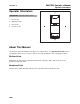
P80/PP25 Operator’s Manual Overview - 2 Serial Number Location Serial Number Location Record serial numbers and date of purchase in spaces provided.
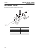
P80/PP25 Operator’s Manual Overview - 3 Unit Components Unit Components 1. Drill rod 2. Jaw lever 3. Rotation device 4. hydraulic hoses 6. Mechanical hydraulic control (optional) 7. Electric Hydraulic Control (Optional) 8. Power unit 5.
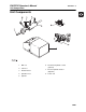
Overview - 4 P80/PP25 Operator’s Manual Unit Components Trench Box T-bar CMW Back Brace
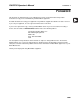
P80/PP25 Operator’s Manual Overview - 5 Intended Use Intended Use The Ditch Witch P80 rod pusher offers a way to bore under sidewalks, roads, or other obstructions without making open cuts. The rod-through-centerline design produces a true, straight bore. Beacon housings, heads, and other options make the unit directional. The P80 Rod pusher is compact and easy to use with either a trench box, back brace, or T-bar set-up configuration.
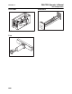
Overview - 6 P80/PP25 Operator’s Manual Operator Orientation Operator Orientation IMPORTANT: Top view of unit is shown. 1. Front of unit 2. Right side of unit 3. Rear of unit 4. Left side of unit About This Manual This manual contains information for the proper use of this machine. See Operation Overview for basic operating procedures. Cross references such as “See page 50” will direct you to detailed procedures.
P80/PP25 Operator’s Manual Foreword - 7 Foreword This manual is an important part of your equipment. It provides safety information and operation instructions to help you use and maintain your Ditch Witch equipment. Read this manual before using your equipment. Keep it with the equipment at all times for future reference. If you sell your equipment, be sure to give this manual to the new owner. If you need a replacement copy, contact your Ditch Witch dealer.
Foreword - 8 P80/PP25 Operator’s Manual P80/PP25 Operator’s Manual Issue number 1.1/OM/02/14 Part number 053-2296 Copyright 2010, 2014 by The Charles Machine Works, Inc. , Ditch Witch, CMW, AutoCrowd, Jet Trac, Roto Witch, Subsite, Fluid Miser, Power Pipe, Super Witch, Pierce Airrow, The Underground, The Underground Authority Worldwide, and Zahn are registered trademarks of The Charles Machine Works, Inc.
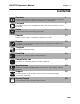
P80/PP25 Operator’s Manual Contents - 9 Contents Overview 1 machine serial number, information about the type of work this machine is designed to perform, basic machine components, and how to use this manual Foreword 7 part number, revision level, and publication date of this manual, and factory contact information Safety 11 machine safety alerts and emergency procedures Controls 21 machine controls, gauges, and indicators and how to use them Prepare 27 procedures for inspecting and classify
Contents - 10 CMW P80/PP25 Operator’s Manual
P80/PP25 Operator’s Manual Safety - 11 Safety Chapter Contents Guidelines . . . . . . . . . . . . . . . . . . . . . . . . . . . . . . . . 12 Safety Alert Classifications . . . . . . . . . . . . . . . . . . 13 Safety Alerts . . . . . . . . . . . . . . . . . . . . . . . . . . . . . . 14 Emergency Procedures . . . . . . . . . . . . . . . . . . . . . 17 • Electric Strike Description . . . . . . . . . . . . . . . . . . . . . . . . . . . . . . . . . . . 17 • If an Electric Line is Damaged . . . . . . . . . .
Safety - 12 P80/PP25 Operator’s Manual Guidelines Guidelines Follow these guidelines before operating any jobsite equipment: • Complete proper training and read operator’s manual before using equipment. • Contact your local One-Call (811 in USA) or the One-Call referral number (888-258-0808 in USA and Canada) to have underground utilities located before digging. Also contact any utilities that do not participate in the One-Call service.
P80/PP25 Operator’s Manual Safety - 13 Safety Alert Classifications Safety Alert Classifications These classifications and the icons defined on the following pages work together to alert you to situations which could be harmful to you, jobsite bystanders or your equipment. When you see these words and icons in the book or on the machine, carefully read and follow all instructions. YOUR SAFETY IS AT STAKE. Watch for the three safety alert levels: DANGER, WARNING and CAUTION. Learn what each level means.
P80/PP25 Operator’s Manual Safety - 14 Safety Alerts Safety Alerts Electric shock. Contacting electric lines will cause death or serious injury. Know location of lines and stay away. Deadly gases. Lack of oxygen or presence of gas will cause sickness or death. Provide ventilation. Moving tools will kill or injure. Never use wrenches or tools on moving rods and bursting unit components when unit is operating. Jobsite hazards could cause death or serious injury. Use correct equipment and work methods.
P80/PP25 Operator’s Manual Safety - 15 Safety Alerts Looking into fiber optic cable could result in permanent vision damage. Do not look into ends of fiber optic or unidentified cable. Fluid or air pressure could pierce skin and cause injury or death. Stay away. Fire or explosion possible. Fumes could ignite and cause burns. No smoking, no flame, no spark. Moving traffic - hazardous situation. Death or serious injury could result.
Safety - 16 P80/PP25 Operator’s Manual Safety Alerts Fall possible. Slips or trips may result in injury. Keep area clean. Battery acid may cause burns. Avoid contact. Improper handling or use of chemicals may result in illness, injury, or equipment damage. Follow instructions on labels and in material safety data sheets (MSDS).
P80/PP25 Operator’s Manual Safety - 17 Emergency Procedures Emergency Procedures Before operating any equipment, review emergency procedures and check that all safety precautions have been taken. EMERGENCY SHUTDOWN - Turn ignition switch to stop position or push remote engine stop button. Electric Strike Description When working near electric cables, remember the following: • Electricity follows all paths to ground, not just path of least resistance.
Safety - 18 P80/PP25 Operator’s Manual Emergency Procedures If an Electric Line is Damaged If you suspect an electric line has been damaged and you are in pit, DO NOT MOVE and DO NOT TOUCH ANYTHING. Remain in pit and take the following actions. The order and degree of action will depend upon the situation. • Warn people nearby that an electric strike has occurred. Instruct them to leave the area and contact utility. • Contact utility company to shut off power.
P80/PP25 Operator’s Manual Safety - 19 Emergency Procedures If a Gas Line is Damaged If you suspect a gas line has been damaged, take the following actions. The order and degree of action will depend on the situation. • Immediately shut off engine(s), if this can be done safely and quickly. • Remove any ignition source(s), if this can be done safely and quickly. • Warn others that a gas line has been cut and that they should leave the area. • Leave jobsite as quickly as possible.
Safety - 20 P80/PP25 Operator’s Manual Emergency Procedures CMW
P80/PP25 Operator’s Manual Controls - 21 Controls Chapter Contents P80 Rod Pusher . . . . . . . . . . . . . . . . . . . . . . . . . . . 22 PP25 Power Pack . . . . . . . . . . . . . . . . . . . . . . . . . .
P80/PP25 Operator’s Manual Controls - 22 P80 Rod Pusher P80 Rod Pusher 1. Jaw lever 4. Mechanical hyraulic control valve (optional) 2. Rotation device (optional) 5. Electric hydraulic control (optional) 3. Level adjusting screw Item Description 1. Jaw lever Push lever to move to pull rod. Pull lever to push rod.
P80/PP25 Operator’s Manual Controls - 23 P80 Rod Pusher Item Description Notes 2. Rotation Device This control rotates rod as it is pushed or pulled. Disengage device to steer rod. 3. Level Adjusting Screw This control allows the unit to be adjusted to match grade of bore. IMPORTANT: Trench box mounted rod pushers do not have level adjusting screws. Entire trench box must be adjusted to set grade of bore. 4. Mechanical Hydraulic Control (Optional) 5.
P80/PP25 Operator’s Manual Controls - 24 PP25 PP25 1. Ignition switch 6. Throttle control 2. Choke control 7. Battery compartment 3. Fuel gauge 8. Case drain hydraulic connector 4. Battery voltmeter 9. Return hydraulic connector 5. Hourmeter 10. Pressure hydraulic connector Item Description Notes 1. Ignition switch To start engine, insert key and turn clockwise. IMPORTANT: If unit won’t start, ensure all emergency stop switches are disengaged. To stop engine, turn key counterclockwise.
P80/PP25 Operator’s Manual Controls - 25 PP25 Item Description Notes 2. Choke control To close choke valve, pull. Close this valve to enrich air/fuel mixture and help start cold engine. Open choke valve after engine runs for a few seconds. 3. Fuel gauge Displays fuel level in tank. 4. Battery voltmeter Displays system voltage. Should show 12-14V with engine running during normal operation. 5. Hourmeter Displays engine operating time. Use these times to schedule service. 6.
P80/PP25 Operator’s Manual Controls - 26 PP25 Item Description Notes 7. Battery compartment To access battery, turn ring and remove door. To disconnect battery, remove negative (black) cable from battery post. 8. Hydraulic coupler, case drain To power hydraulic equipment, connect hydraulic line to connector. NOTICE: Couplers do not connect under pressure. Do not attempt to connect hydraulic lines while unit is operating. Stop PP25 engine before connecting hydraulic lines. 9.
P80/PP25 Operator’s Manual Prepare - 27 Prepare Chapter Contents Gather Information . . . . . . . . . . . . . . . . . . . . . . . . . 28 • Review Job Plan . . . . . . . . . . . . . . . . . . . . . . . . . . . . . . . . . . . . . . . . . . 28 • Notify One-Call Services . . . . . . . . . . . . . . . . . . . . . . . . . . . . . . . . . . . . 28 • Arrange for Traffic Control. . . . . . . . . . . . . . . . . . . . . . . . . . . . . . . . . . . 28 • Plan for Emergency Services . . . . . . . . . . . . . .
Prepare - 28 P80/PP25 Operator’s Manual Gather Information Gather Information A successful job begins before you dig. The first step in planning is reviewing information already available about the job and jobsite. Review Job Plan Review blueprints or other plans. Check for information about existing or planned structures, elevations, or proposed work that may be taking place at the same time.
P80/PP25 Operator’s Manual Prepare - 29 Inspect Site Inspect Site Inspect jobsite before transporting equipment. Check for the following: • changes in elevation such as hills or other open trenches • obstacles such as buildings, railroad crossings, or streams • signs of utilities (See “Inspect Jobsite” on page 30.) • traffic • access • soil type and condition Identify Hazards Identify safety hazards and classify jobsite. See “Classify Jobsite” on page 30.
Prepare - 30 P80/PP25 Operator’s Manual Classify Jobsite Classify Jobsite Inspect Jobsite • Follow U.S. Department of Labor regulations on excavating and trenching (Part 1926, Subpart P) and other similar regulations. • Contact your local One-Call (811 in USA) or the One-Call referral number (888-258-0808 in USA and Canada) to have underground utilities located before digging. Also contact any utilities that do not participate in the One-Call service.
P80/PP25 Operator’s Manual Prepare - 31 Classify Jobsite Apply Precautions Once classified, precautions appropriate for jobsite must be taken. Electric Jobsite Precautions Use one or both of these methods. • Expose line by careful hand digging or soft excavation. • Have service shut down while work is in progress. Have electric company test lines before returning them to service.
Prepare - 32 P80/PP25 Operator’s Manual Plan Bore Path Plan Bore Path Plan the bore path, from entry to end, before job begins. Locate the entire route of the material to be installed to ensure a straight path. For complicated bores, consult an engineer. Have jobsite surveyed and bore path calculated. Expose all crossing or parallel utilities within 18” (500 mm) of the material being installed. Mark Bore Path Mark your planned bore path with flags or paint.
P80/PP25 Operator’s Manual Prepare - 33 Prepare Jobsite Prepare Jobsite Jobsite hazards could cause death or serious injury. Use correct equipment and work methods. Use and maintain proper safety equipment. NOTICE: • Cutting high voltage cable can cause electrocution. Expose lines by hand before digging. • All vegetation near operator’s station must be removed. Contact with trees, shrubs, or weeds during electrical strike could result in electrocution.
Prepare - 34 P80/PP25 Operator’s Manual Check Supplies and Prepare Equipment Check Supplies and Prepare Equipment Supplies • fuel • keys • personal protective equipment, such as hard hat and safety glasses Fluid Levels • fuel • hydraulic fluid • battery charge • engine oil Condition and Function • fan belts • filters (air, oil, hydraulic) • pumps and motors • hoses and valves • signs, guards, and shields Accessories Fire Extinguisher If required, mount a fire extinguisher near the
P80/PP25 Operator’s Manual Transport - 35 Transport Chapter Contents Lift Points and Procedure . . . . . . . . . . . . . . . . . . . 36 • Power Pack . . . . . . . . . . . . . . . . . . . . . . . . . . . . . . . . . . . . . . . . . . . . . 36 • Rod Pusher . . . . . . . . . . . . . . . . . . . . . . . . . . . . . . . . . . . . . . . . . . . . . . 37 • Rod Pusher with T-Bar . . . . . . . . . . . . . . . . . . . . . . . . . . . . . . . . . . . . . 37 • Rod Box . . . . . . . . . . . . . . . . . . . . .
P80/PP25 Operator’s Manual Transport - 36 Lift Points and Procedure Lift Points and Procedure Crushing weight. If load falls or moves it could kill or crush you. Use proper procedures and equipment or stay away. Lifting points are identified by lifting decals. Lifting at other points is unsafe and can damage machinery. Use equipment capable of supporting the size and weight of the unit being lifted. See “Specifications” on page 99 or measure and weigh equipment before lifting.
P80/PP25 Operator’s Manual Transport - 37 Lift Points and Procedure Rod Pusher Use equipment capable of supporting the unit's size and weight. See “Specifications” on page 99 or measure and weigh equipment before lifting. Lift rod pusher by connecting chain to lift ring. Rod Pusher with T-Bar Attach chain to front lift point. Rod Box Use equipment capable of supporting the rod box's size and weight. Attach chains to lift rings.
Transport - 38 P80/PP25 Operator’s Manual Lift Points and Procedure Trench Box Lift trench box by attaching four chains to lift points and to a common lift ring. Chains must be: • at least 80 in (2030 mm) fromlift points to lift ring, • of equal length, • strong enough to bear 10,000 lb (44,500 N) lifting force. Maximum allowable lifting force is 20,000 lb (89,000 N).
P80/PP25 Operator’s Manual Transport - 39 Back Brace Lift unit with back brace by attaching chain to lift rings at front and back of back brace. Lift back brace support by lift ring at top of support. Tie Down Points and Procedure Rod pusher, rod box, back brace, and trench box may be carried on any truck or trailer able to transport the equipment gross weight. • Install all pins to hold rod pusher in place. • Use tie-downs to anchor equipment.
Transport - 40 P80/PP25 Operator’s Manual Tie Down Points and Procedure CMW
P80/PP25 Operator’s Manual Push Rods - 41 Push Rods Chapter Contents Setup . . . . . . . . . . . . . . . . . . . . . . . . . . . . . . . . . . . . 42 • Trench Box . . . . . . . . . . . . . . . . . . . . . . . . . . . . . . . . . . . . . . . . . . . . . . 42 • Back Brace . . . . . . . . . . . . . . . . . . . . . . . . . . . . . . . . . . . . . . . . . . . . . . 45 • T-Bar . . . . . . . . . . . . . . . . . . . . . . . . . . . . . . . . . . . . . . . . . . . . . . . . . . . 46 Assemble Strike System .
P80/PP25 Operator’s Manual Push Rods - 42 Setup Setup Read operator’s manual. Know how to use all controls before operating machine. When you see this sign caution. Your safety is at stake. on the machine or in the manual, read it and use Proper set-up and bracing is necessary for efficient rod pushing and pulling. Rod pushers can be used with three configurations: trench box, back brace, and T-bar. Set-up and bracing procedures depend on configuration used.
P80/PP25 Operator’s Manual Push Rods - 43 Setup 7. Install pins, as shown. 8. Slide a rod through cylinder and install pilot head, as shown. 9. Fasten chain and lift rod pusher in level position. Lower unit into trench. 10. Backfill and compact soil around trench box. Top 2’ (600 mm) of soil must be well compacted.
Push Rods - 44 P80/PP25 Operator’s Manual Setup 11. Attach hydraulic control hose to power unit and rod pusher. 12. Set up Electric Strike System. See instructions later in this chapter.
P80/PP25 Operator’s Manual Push Rods - 45 Setup Back Brace 1. Dig starting trench 18” (460 mm) wide and 72-99” (1830-2500 mm) long. 2. Level and compact trench floors. 3. Dig target trench deep enough to meet bore path and long enough to remove rod. 4. Slide a rod through cylinder and install pilot head. 5. Fasten chain and lift rod pusher in level position. Lower unit into trench. 6. Attach hydraulic control hoses to power unit hydraulic manifold.
Push Rods - 46 P80/PP25 Operator’s Manual Setup T-Bar 1. Dig T-Bar trench a minimum of 6” (150 mm) wide. 2. Dig rod pusher trench a minimum of 9” (230 mm) wide. Do not break edges or corners of T-Bar trench. 3. Dig rod trench, as shown. Trench should be slightly longer than rod being used. Level and compact trench floors. 4. Dig target trench deep enough to meet bore path and long enough to remove rod. 5. Set T-bar on cylinder and install clip pins.
P80/PP25 Operator’s Manual Push Rods - 47 Setup 6. Slide a rod through cylinder and install pilot head. 7. Fasten chain and lift rod pusher in level position. Lower unit into trench. 8. Attach hydraulic control hoses to power unit hydraulic manifold. Connect other hoses from hydraulic control valve block to rod pusher. NOTICE: Hydraulic hoses DO NOT connect under pressure. Stop unit before connecting hydraulic hoses. 9. Align Unit with intended bore path. 10. Place a level on push rod at rear of unit.
Push Rods - 48 P80/PP25 Operator’s Manual Assemble Strike System Assemble Strike System Anytime rod pusher with trench box is used in an electric jobsite, a trench box with electric strike system and directional boring system must be properly set up, tested, and used. In addition to control box, electric strike system includes grid mats, bonding cables, barriers, and protective boots and gloves meeting the following standards: • Wear high-top boots with legs of pants tucked completely inside.
P80/PP25 Operator’s Manual Push Rods - 49 Assemble Strike System Arrange Grid Mats A. Bore Path B. Trench Box C. Trailer D. Strike System Control Box E. Power unit 1. Arrange grid mats around trench box. 2. Arrange grid mats between trench box and trailer. 3. Stake grid mats. 4. Place floor grids on rail on trench box floor. Position grids at end opposite rod pusher and with bonding cables on same side as welded tab.
Push Rods - 50 P80/PP25 Operator’s Manual Assemble Strike System Assemble Bonding Equipment 1. Drive voltage stake into ground at least 6 ft (2 m) from starting trench. 2. Clip voltage limiter to voltage stake. 3. Connect cable from voltage limiter to back of control box and lock with 1/4 turn. 4. Connect bonding cables to grid mats. 5. Drive ground rod into soil near grid mats. 6. Move cords and cables under grid mats.
P80/PP25 Operator’s Manual Push Rods - 51 Assemble Strike System Install Control Box and Cables 1. Attach control box to mounting bracket with wing nuts. 2. Attach current coil cable to top of current coil assembly • Attach blue or green connector at (A). • Attach black connector at (B). • Attach brown or white connector at (C). 3. Plug current coil into back of control box. 4. Plug power cable into back of control box. 5. Attach bonding cable to top of rod pusher. 6.
P80/PP25 Operator’s Manual Push Rods - 52 Assemble Strike System Connect to Power Read operator’s manual. Know how to use all controls before operating machine. When you see this sign caution. Your safety is at stake. on the machine or in the manual, read it and use NOTICES: • Low main battery power will shut off control box. Backup battery only signals loss of main power. Restore main power before continuing.
P80/PP25 Operator’s Manual Push Rods - 53 Assemble Strike System Test Strike System If system fails any part of this test, see “Troubleshooting the Strike System” in MAINTENANCE. Do not bore until test is completed successfully. 1. Turn power switch on. Light above switch should come on. 2. Check that Lo Main and Lo Backup lights are off. 3. Press test button. • Horns on boring unit and power unit will sound. • Strobe lights on both units will flash.
P80/PP25 Operator’s Manual Push Rods - 54 Operate Operate Crushing weight. If load falls or moves, it could kill or crush you. Use proper procedures or stay away. NOTICE: Cave-in possible. Read, understand, and follow US Department of Labor Regulations on Excavating and Trenching, Part 1926, Subpart P. Jobsite hazards could cause death or serious injury. Use correct equipment and work methods. Use and maintain proper safety equipment. Fluid or air pressure could pierce skin and cause injury or death.
P80/PP25 Operator’s Manual Push Rods - 55 Operate Pushing Straight 1. Start power pack. 2. Push pilot head against front wall of trench. 3. Activate hydraulic control. 4. Pull jaw lever back gently. Rod will enter soil. 5. Push jaw lever forward, then gently pull it back again. NOTICE: Do not clamp jaws on rod threads. 6. As needed, connect new rod, tighten with pipe wrench, and continue pushing. Changing Direction 1. Select directional head and attach to beacon housing.
Push Rods - 56 P80/PP25 Operator’s Manual Operate Expanding and Pullback Expanding A. Rod B. Bell Stop C. Expander D. Clevis 1. When rod reaches target trench, attach bell stop, expander, and another bell stop. Use clevis to attach material to drill string. 2. Pull expander back through bore. If bore will be expanded further, add rod sections behind expander to keep drill string in bore. 3. When expander is in set-up trench, remove expander and both expander stops. 4.
P80/PP25 Operator’s Manual Complete the Job - 57 Complete the Job Chapter Contents Stow Components . . . . . . . . . . . . . . . . . . . . . . . . . 58 Restore Jobsite . . . . . . . . . . . . . . . . . . . . . . . . . . . 58 Stow Tools. . . . . . . . . . . . . . . . . . . . . . . . . . . . . . . .
Complete the Job - 58 P80/PP25 Operator’s Manual Stow Components Stow Components 1. Install all covers. 2. Load components onto trailer. 3. Secure all components on trailer. Restore Jobsite Fill in installation, bursting and service connection pits. Stow Tools Make sure all components, accessories and tools are loaded and properly secured on trailer.
P80/PP25 Operator’s Manual Specifications - 59 P80 w/Trench Box Specifications P80 w/Trench Box Dimensions P80 U.S. Metric Basic weight 253 lb 115 kg L, length 108 in 2750 mm W, width 36 in 920 mm H1, height 48 in 1220 mm H2, Height from base to centerline of bore 8.4 in 213 mm Weight, trench box 930 lb 420 kg Operating weight w/P80 installed 1240 lb 560 kg Operating weight w/P80 and 42 4-ft rods 2700 lb 1225 kg Trench Box Operational U.S.
Specifications - 60 P80/PP25 Operator’s Manual P80 w/Trench Box P80 w/Back Brace Dimensions P80 U.S. Metric Basic weight 253 lb 115 kg L2, Length, min to max 72-100 in 1800-2500 mm A, Width 17 in 430 mm H3, Height 18 in 450 mm D, Height from base to centerline of bore 7.6 in 190 mm Level adjustment height 6 in 150 mm Weight, back brace 440 lb 200 kg Operating weight w/P80 installed 704 lb 320 kg Back Brace Operational U.S.
P80/PP25 Operator’s Manual Specifications - 61 P80 w/Trench Box P80 w/T-Bar Dimensions P80 U.S. Metric Basic weight 253 lb 115 kg A, Cylinder diameter 8 in 200 mm B, T-Bar width 5.8 in 145 mm C, T-Bar height 12 in 203 mm D, Base to cylinder centerline 7.2 in 183 mm H3, Height without handle 16 in 400 mm L3, Length, T-bar installed with cylinder retracted 42 in 1050 mm W2, Width, T-bar 72 in 1800 mm Push rod diameter 1.
Specifications - 62 P80/PP25 Operator’s Manual P80 w/Trench Box Operational U.S. Metric Stroke, each cycle 9 in 229 mm Bore diameter, max.
P80/PP25 Operator’s Manual Specifications - 63 PP25 PP25 Dimensions U.S. Metric L, length 48.5 in 1.23 m W, width 27.
Specifications - 64 P80/PP25 Operator’s Manual PP25 Power U.S. Metric Displacement 42 in3 688 cm3 Bore 3.03 in 77 mm Stroke 2.83 in 72 mm manufacturer’s gross power rating (per SAE J1995) 22.2 hp 16.6 kW rated speed 3600 rpm 3600 rpm Engine: Honda GX690, EPA Phase III Fuel: gasoline Cooling medium: air Cylinders: 2 Power Hydraulic System U.S. Metric Flow capacity @ 3200 rpm 11.7 gpm 44.
P80/PP25 Operator’s Manual Support - 65 Procedure Support Procedure Notify your dealer immediately of any malfunction or failure of Ditch Witch® equipment. Always give model, serial number, and approximate date of your equipment purchase. This information should be recorded and placed on file by the owner at the time of purchase. Return damaged parts to dealer for inspection and warranty consideration if in warranty time frame.
P80/PP25 Operator’s Manual Warranty - 66 Warranty Ditch Witch® Equipment and Replacement Parts Limited Warranty Policy Subject to the limitation and exclusions herein, free replacement parts will be provided at any authorized Ditch Witch dealership for any Ditch Witch equipment or parts manufactured by The Charles Machine Works, Inc. (CMW) that fail due to a defect in material or workmanship within one (1) year of first commercial use.
P80/PP25 Operator’s Manual Service Record - 69 Service Record Service Performed Date Hours CMW®
Service Record - 70 Service Performed CMW® P80/PP25 Operator’s Manual Date Hours