OnGrade Operator’s Manual CMW® Issue 1.
OnGrade Operator’s Manual Overview - 1 Overview Chapter Contents Serial Number Location . . . . . . . . . . . . . . . . . . . . . . 2 Intended Use . . . . . . . . . . . . . . . . . . . . . . . . . . . . . . 3 About This Manual . . . . . . . . . . . . . . . . . . . . . . . . . . 3 • Bulleted Lists . . . . . . . . . . . . . . . . . . . . . . . . . . . . . . . . . . . . . . . . . . . . . .3 • Numbered Lists . . . . . . . . . . . . . . . . . . . . . . . . . . . . . . . . . . . . . . . . . . . .
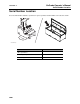
OnGrade Operator’s Manual Overview - 2 Serial Number Location Serial Number Location Record serial numbers and date of purchase in spaces provided. Serial numbers are located as shown. e14om007t.
OnGrade Operator’s Manual Overview - 3 Intended Use Intended Use The primary components of the OnGrade system include an 8500TK tracker, an 850BG grade beacon, an 8500GP grade pole to mount the tracker on, and grade pole extensions.
Overview - 4 OnGrade Operator’s Manual FCC Statement - Internal Transmitter FCC Statement - Internal Transmitter Contains FCC ID: TFB-FREESTAR Contains IC: 5969A-FREESTAR This device complies with Part 15 of the FCC Rules. Operation is subject to the following two conditions: (1) this device may not cause harmful interference, and (2) this device must accept any interference received, including interference that may cause undesired operation.
OnGrade Operator’s Manual Foreword - 5 Foreword This manual is an important part of your equipment. It provides safety information and operation instructions to help you use and maintain your Ditch Witch equipment. Read this manual before using your equipment. Keep it with the equipment at all times for future reference. If you sell your equipment, be sure to give this manual to the new owner. If you need a replacement copy, contact your Ditch Witch dealer.
OnGrade Operator’s Manual Foreword - 6 OnGrade Operator’s Manual Issue number 1.0/OM-2/10 Part number 053-1393 Copyright 2010 by The Charles Machine Works, Inc. , Ditch Witch, CMW, AutoCrowd, Jet Trac, Roto Witch, Subsite, Fluid Miser, Power Pipe, Super Witch, Pierce Airrow, The Underground, The Underground Authority Worldwide, and Zahn are registered trademarks of The Charles Machine Works, Inc. This product is covered by the following patents: U.S. 7510029; DE (Germany) 602006008328.
OnGrade Operator’s Manual Contents - 7 Contents Overview 1 machine serial number, information about the type of work this machine is designed to perform, basic machine components, and how to use this manual Foreword 5 part number, revision level, and publication date of this manual, and factory contact information Safety 9 machine safety alerts and emergency procedures Controls 13 machine controls and how to use them Conduct OnGrade Bore 25 procedures for setting up, drilling, and backreamin
Contents - 8 CMW OnGrade Operator’s Manual
OnGrade Operator’s Manual Safety - 9 Safety Chapter Contents Guidelines . . . . . . . . . . . . . . . . . . . . . . . . . . . . . . . . 10 Safety Alert Classifications . . . . . . . . . . . . . . . . . . 11 Safety Alerts . . . . . . . . . . . . . . . . . . . . . . . . . . . . . .
Safety - 10 OnGrade Operator’s Manual Guidelines Guidelines Follow these guidelines before operating any jobsite equipment: • Complete proper training and read operator’s manual before using equipment. • Contact One-Call (888-258-0808) and any utility companies which do not subscribe to One-Call. Have all underground pipes and cables located and marked before operating equipment. If you damage a utility, contact utility company.
OnGrade Operator’s Manual Safety - 11 Safety Alert Classifications Safety Alert Classifications These classifications and the icons defined on the following pages work together to alert you to situations which could be harmful to you, jobsite bystanders or your equipment. When you see these words and icons in the book or on the unit, carefully read and follow all instructions. YOUR SAFETY IS AT STAKE. Watch for the three safety alert levels: DANGER, WARNING and CAUTION. Learn what each level means.
OnGrade Operator’s Manual Safety - 12 Safety Alerts Safety Alerts IMPORTANT: See drilling unit operator’s manual for others hazards related to drilling activities. Electric shock. Contacting electric lines will cause death or serious injury. Know location of lines and stay away. Jobsite hazards could cause death or serious injury. Use correct equipment and work methods. Use and maintain proper safety equipment. Explosion possible. Serious injury or equipment damage could occur.
OnGrade Operator’s Manual Controls - 13 Controls Chapter Contents Grade Pole . . . . . . . . . . . . . . . . . . . . . . . . . . . . . . . 14 • Controls . . . . . . . . . . . . . . . . . . . . . . . . . . . . . . . . . . . . . . . . . . . . . . . . .14 • Indicators . . . . . . . . . . . . . . . . . . . . . . . . . . . . . . . . . . . . . . . . . . . . . . . .15 • Detectors . . . . . . . . . . . . . . . . . . . . . . . . . . . . . . . . . . . . . . . . . . . . . . . .16 Laser, Level, and Camera . . .
OnGrade Operator’s Manual Controls - 14 Grade Pole Grade Pole Controls 1 4 2 3 e14om001t.eps 1. Depth button 3. On/Off button 2. Handle 4. Lock Item Description Notes 1. Depth button To take depth reading and send it to tracker, press. Grade pole sends information only when green indicator is lit. 2. Handle To raise sensor, turn clockwise. To lower sensor, turn counterclockwise. 3. On/Off button To turn grade pole on, press until blue light in comes on.
OnGrade Operator’s Manual Controls - 15 Grade Pole Indicators 2 1 e14om004t.eps 1. Low/High indicators 2. On-grade indicator Item Description Notes 1. Low/High indicators Upper and lower (red) lights indicate direction to adjust pole to center laser plane in a laser detector. Upper light indicates pole is high. Center (green) light indicates laser plane is centered in one of the laser detectors. Take depth readings when this indicator is on. 2.
OnGrade Operator’s Manual Controls - 16 Laser, Level, and Camera Detectors e14om011t.eps Item Description Notes Laser detectors Detect laser plane. No control box lights will be lit unless one of the detectors is hit by the rotating laser plane. Laser, Level, and Camera IMPORTANT: See manufacturer’s documentation for information about laser, level, and camera controls.
OnGrade Operator’s Manual Controls - 17 8500TK Grade Mode 8500TK Grade Mode For standard operation, see 8500 Tracking System operator’s manual (p/n 053-1254). Icons 1 3 2 4 13 45.2” 5 +61” 54° 6 0.1% 12 15” 72°F 4” 11 10 11k 9 7 8 e14om009t.eps 1. Beacon battery life indicator 8. Beacon frequency indicator 2. Laser plane height above ground 9. Tracker battery indicator 3. Laser plane distance to center of beacon 10. Beacon left/right distance indicator 4.
OnGrade Operator’s Manual Controls - 18 8500TK Grade Mode Item Description 1. Beacon battery life indicator Graphically indicates battery life remaining. Notes If beacon is within 5 minutes of entering sleep mode, a countdown timer will appear below icon. c00ic072t.eps An “L” appears in the icon if a Lithium battery is installed. 2. Laser plane height above ground Distance from the laser plane to the ground surface. 3.
OnGrade Operator’s Manual Controls - 19 8500TK Grade Mode Item Description 7. Communication indicator Indicates tracker is transmitting. Notes c00ic075t.eps 8. Beacon frequency indicator Displays “11k” when high frequency beacon is selected. Displays “2k” when low frequency beacon is selected. 9. Tracker battery indicator Indicates amount of battery power remaining for the tracker. Flashes when batteries need to be replaced. c00ic076t.eps 10.
OnGrade Operator’s Manual Controls - 20 8500TK Grade Mode Item Description 12. Beacon pitch indicator Displays pitch of beacon in percent grade or degrees. 0.1% Notes The arrow behind the value indicates whether pitch is positive or negative. c00ic080t.eps 13. Virtual bubble level Graphically represents the tilt of the grade pole. c00ic081t.eps Buttons See 8500 Operator’s Manual for information about these controls.
OnGrade Operator’s Manual Controls - 21 8500TK Grade Mode Menu Overview 1 3 2 1 -+ 3 2 4 501 0.1% 5 6 4 e14om010t.eps 1. Drill-Thru mode 4. Service menu 2. Beacon settings 5. Display settings 3. Radio options 6. System settings Item Description 1. Drill-Thru mode Highlight icon and press select to enter the drill-thru mode. Notes c00ic079t.
OnGrade Operator’s Manual Controls - 22 8500TK Grade Mode Item Description Notes 2. Beacon settings Highlight icon and press select to enter the “beacon settings” menu. See “Beacon Settings” on page 23. Highlight icon and press select to enter the “radio options” mode. See “Radio Options” on page 24. Highlight icon and press select to enter “service menu.” See “Service Menu” on page 24. Highlight icon and press select to enter the “display settings” menu. See “Display Settings” on page 23.
OnGrade Operator’s Manual Controls - 23 8500TK Grade Mode Descriptions Display Settings Description Notes LCD brightness Controls LCD backlight intensity. Available settings: 0 (off) to 100 (brightest, default). LCD contrast Controls contrast of LCD. Available settings: -20 (lighter) to 20 (darker), 0 is default. Units Controls displayed units of depth values, temperatures and other numbers. Available distance settings: inches, ft in (default), decimal ft, meters, centimeters. Depth disp.
OnGrade Operator’s Manual Controls - 24 8500TK Grade Mode Radio Options Description Notes Radio power Turns radio on and off. Available settings: on (default), off. Channel Sets telemetry channel Available settings: 1 (default) through 15 OnGrade channel Sets channel for OnGrade pole communication Available settings: 1 (default) through 3 Tracker Control Enables or disables thrust and rotation of drilling unit. Available settings: Rig ON, Rig OFF (default).
OnGrade Operator’s Manual Conduct OnGrade Bore - 25 Conduct OnGrade Bore Chapter Contents OnGrade Process Overview . . . . . . . . . . . . . . . . . 26 Calibrate System . . . . . . . . . . . . . . . . . . . . . . . . . . 29 • Set Up Fixture . . . . . . . . . . . . . . . . . . . . . . . . . . . . . . . . . . . . . . . . . . . .29 • Calibrate Depth, Roll, and Pitch . . . . . . . . . . . . . . . . . . . . . . . . . . . . . . .29 Set Up Laser Plane . . . . . . . . . . . . . . . . . . . . . . . .
OnGrade Operator’s Manual Conduct OnGrade Bore - 26 OnGrade Process Overview OnGrade Process Overview 1 3 2 4 5 e14om005t.eps 1. start pit 4. end pit 2. laser plane 5. tripod and laser 3. grade pole and tracker 1. Determine start and end pits. See “Job Plans” on page 38. 2. Select downhole tools for pilot bore. See “Downhole Tools” on page 42. 3. Calibrate system. See “Calibrate Depth, Roll, and Pitch” on page 29. 4.
OnGrade Operator’s Manual Conduct OnGrade Bore - 27 OnGrade Process Overview 6. Drill into the start pit and verify that drill head is at the proper depth. Turning shaft will kill you or crush arm or leg. Stay away. NOTICE: • Tracker operator and drill operator should maintain two-way communication. • Keep everyone clear of the exposed drill string. • No one should enter pit until clear communication is given by the drill operator that the drill unit is shut down.
OnGrade Operator’s Manual Conduct OnGrade Bore - 28 OnGrade Process Overview 10. Use tracker to locate drill head and take initial reading. See “Initial” on page 34. This reading from laser plane to center of beacon is the target value for the bore. 11. Add pipe, drill in and take readings as directed below until drill head enters end pit. IMPORTANT: Take pitch and depth readings at the same roll position. • pitch: every 12-18” (30-45 cm) with drill head stopped • depth: every 5-10’ (1.
OnGrade Operator’s Manual Conduct OnGrade Bore - 29 Calibrate System Calibrate System Set Up Fixture 1. Unfold calibration fixture away from metal objects and on reasonably level ground. 2. Install battery in beacon and place beacon in beacon housing. 3. Place beacon and tracker in fixture, as shown. • Left pod of tracker should point toward beacon end of fixture. • Bit end of beacon should point same direction as tracker display. 4. Calibrate SmartTool level according to manufacturer’s instructions.
OnGrade Operator’s Manual Conduct OnGrade Bore - 30 Calibrate System Roll Turn drill housing to 12 o’clock position and verify roll position on tracker. If it is incorrect when using an endload housing, verify that the timing slot on the front of the beacon is engaged with the locating pin in the housing. If it is still incorrect or when using a sideload housing, select “Roll Calibration” in “Beacon Settings” menu and follow prompts. Pitch 1.
OnGrade Operator’s Manual Conduct OnGrade Bore - 31 Set Up Laser Plane Set Up Laser Plane 1 3 2 4 5 e14om005t.eps NOTICE: The Laser Reference AS2 is a Class II laser. The normal blink, or eye-aversion, reflex is sufficient to prevent optical damage due to incidental viewing of a Class II laser. Do not look or stare into laser beam. On Bore Path The laser system is limited by line of sight. Setting up with that in mind can minimize how many times the laser must be repositioned during the bore.
OnGrade Operator’s Manual Conduct OnGrade Bore - 32 Set Up Laser Plane Extension Pole Use up to two extension poles to raise the upper laser plane receptor. 1. Remove cap from top of grade pole. 2. Install cap on top of extension pole and secure with clamps. 3. Insert extension pole into top of grade pole and secure with clamps. IMPORTANT: Grade pole will not work without cap installed. Offset 1.
OnGrade Operator’s Manual Conduct OnGrade Bore - 33 Set Up Laser Plane Repositioning During Bore 1 2 3 A B e14om018t.eps 1. Set up laser in front of obstruction (laser position 1). 2. When it is time to reposition the laser, use laser receiver to detect laser plane and make a mark on a reference point (telephone pole or other stable object). 3. Move up the reference point a known distance (A) that will allow obstruction to be cleared. 4.
Conduct OnGrade Bore - 34 OnGrade Operator’s Manual Take Readings Take Readings Change Grade Pole Channel 1. With grade pole off, press and hold power button until grade pole comes on and blue light turns purple. 2. Look at indicator lights to determine current channel. Upper light is channel 1, center light is channel 2, and lower light is channel 3. 3. Press depth button to cycle through channels. 4. Press and hold depth button once desired channel is selected.
OnGrade Operator’s Manual Conduct OnGrade Bore - 35 Take Readings Regular 1. Use tracker arrows to get grade pole close to the beacon. 2. Check virtual bubble level to ensure grade pole is straight up and down. 3. Gradually move the base until the arrows become black diamonds. 4. Adjust grade pole until middle (green) light comes on. 5. Look at bubble level on tracker to verify grade pole is still straight up and down. 6. Press depth button on grade pole to take depth reading.
OnGrade Operator’s Manual Conduct OnGrade Bore - 36 Correct Depth Drill-Thru Drill-thru mode on the tracker provides left/right guidance information as well as pitch information. Depth information provided when using drill-thru mode can be ignored when conducting an OnGrade bore. 1 2 3 4 5 IMPORTANT: See tracker manual for additional drill-thru mode instructions. 1. Stretch a string on the ground surface along the bore path (2). 2. Place tracker ahead of the front of the drill e14om014t.
OnGrade Operator’s Manual Grade Boring Concepts - 37 Grade Boring Concepts Chapter Contents Theory of Operation . . . . . . . . . . . . . . . . . . . . . . . . 38 • Job Plans . . . . . . . . . . . . . . . . . . . . . . . . . . . . . . . . . . . . . . . . . . . . . . . .38 • Laser Plane . . . . . . . . . . . . . . . . . . . . . . . . . . . . . . . . . . . . . . . . . . . . . .38 • Depth Limitation . . . . . . . . . . . . . . . . . . . . . . . . . . . . . . . . . . . . . . . . . . . . .
OnGrade Operator’s Manual Grade Boring Concepts - 38 Theory of Operation Theory of Operation Job Plans For most jobs, engineers will lay out the line and will establish the manhole locations, the depth the sewer line needs to run, and the recommended grade for the installation. On jobs where a connection is being made to an existing service, the position of the existing sewer line will dictate the depth. Engineers commonly base the plans for a sewer line on the invert, or flowline, of the installation.
OnGrade Operator’s Manual Grade Boring Concepts - 39 Theory of Operation Depth Limitation The depth measurement accuracy of the 8500TK tracker is reduced when the beacon is more than 30’ (9.1 m) below the tracker or 29’ (8.8 m) below the ground surface when tracker is mounted on the grade pole. For short sections of a bore which are deeper than this, continue drilling using only pitch information until the depth is less than 29’ (8.8 m).
Grade Boring Concepts - 40 OnGrade Operator’s Manual Theory of Operation CMW
OnGrade Operator’s Manual Systems and Equipment - 41 Systems and Equipment Chapter Contents Dowhole Tools . . . . . . . . . . . . . . . . . . . . . . . . . . . . 42 • Pilot bore . . . . . . . . . . . . . . . . . . . . . . . . . . . . . . . . . . . . . . . . . . . . . . . .42 • Backream . . . . . . . . . . . . . . . . . . . . . . . . . . . . . . . . . . . . . . . . . . . . . . . .43 OnGrade Management System Software . . . . . . . 45 Inspection Tools . . . . . . . . . . . . . . . . . . . . . . . . . .
OnGrade Operator’s Manual Systems and Equipment - 42 Downhole Tools Downhole Tools Pilot Bore • Endload beacon housing: provides more torsional stiffness and more uniform beacon signal strength regardless of roll position compared to sideload housing. • Pocket bit (1) or slant-faced head with grade Tuff bit (2): both cut a hole slightly larger than the diameter of the beacon housing for a straighter bore path.
OnGrade Operator’s Manual Systems and Equipment - 43 Downhole Tools • Grade transition sub: is stiffer than standard transition subs and helps maintain a straight bore path. Reduces the drill head’s tendency to deviate from a straight line. e14om029t.eps Backream Tools • Flail backreamer: provides very thorough mixing action to create a flowable soil slurry and has support wings to help maintain the vertical position of the reamer in the bore hole in softer soils.
Systems and Equipment - 44 OnGrade Operator’s Manual Downhole Tools Process The tools, fluid rate, drilling fluid and process used for backreaming and pulling in pipe will vary based on soil conditions and operator’s experience and knowledge of the soils in the area. A few key points to consider are: • Make as few passes through the bore hole as possible.
OnGrade Operator’s Manual Systems and Equipment - 45 OnGrade Management System Software OnGrade Management System Software The OnGrade Management System (OGMS) plotting software is configured to work with the information taken at the start and end of a gravity sewer bore, and with the information obtained from the grade pole during the bore. The software can be used during the bore by connecting a laptop computer to the output port on the drilling unit display.
OnGrade Operator’s Manual Systems and Equipment - 46 Inspection Tools Camera/Video Recorder Operation IMPORTANT: See camera and video recorder operator’s manuals for operating instructions. Connection 1. Spool off enough cable to pass competely through installed pipe. IMPORTANT: Camera cable spool provided has 500’ (152 m) of cable. If installed pipe run is longer than this, run trolley as far as possible and then set up trolley in other end of installed pipe to record the rest of the run. 2.
OnGrade Operator’s Manual Systems and Equipment - 47 Job Box Job Box Stow Tools Place all OnGrade system components in job box for transport from the jobsite. Lid 1. Trolley 2. Surveyor’s rod 3. Level 1 2 3 e14om020t.eps Box 1 3 2 4 1. Cable spool 2. Tool box 3. Calibration tool 4. Tripod 5. Laser 6. Tracker 7. Grade pole 7 6 5 e14om021t.
OnGrade Operator’s Manual Systems and Equipment - 48 Job Box Lift Use a forklift or crane capable of supporting the equipment's size and weight. See “Specifications” on page 57 or measure and weigh equipment before lifting. • If using forklift, slide forks into slots on sides (as shown) or ends of box. • If using crane, use top lift points. e14om008t.eps Tie Down Properly tie down unit on truck or trailer before transport.
OnGrade Operator’s Manual Complete the Job - 49 Complete the Job Chapter Contents Inspect Installation . . . . . . . . . . . . . . . . . . . . . . . . . 50 Disconnect . . . . . . . . . . . . . . . . . . . . . . . . . . . . . . . 51 Stow Tools . . . . . . . . . . . . . . . . . . . . . . . . . . . . . . .
Complete the Job - 50 OnGrade Operator’s Manual Inspect Installation Inspect Installation After the product pipe is pulled back, clean out the pipe and inspect the installation. 1. Use surveying rod and laser receiver to take distance measurement from laser plane to top of installed pipe at start and end pits. Ensure laser is set up exactly as it was during the bore. 2. Tie a small rope to the correct size of foam cleanout pig.
OnGrade Operator’s Manual Complete the Job - 51 Disconnect Disconnect • Disconnect and store all drilling components. See drilling unit operator’s manual. • Remove batteries and put all tracking and OnGrade components in job box and storage cases. Stow Tools Make sure all wrenches, bits, pullback devices, and other tools are secured on trailer.
Complete the Job - 52 OnGrade Operator’s Manual Stow Tools CMW
OnGrade Operator’s Manual Service - 53 Service Chapter Contents General Care . . . . . . . . . . . . . . . . . . . . . . . . . . . . . . 54 Troubleshoot Grade Pole . . . . . . . . . . . . . . . . . . . 54 Change Batteries . . . . . . . . . . . . . . . . . . . . . . . . . .
OnGrade Operator’s Manual Service - 54 General Care General Care Under normal operating conditions, all OnGrade system components need only minor maintenance. Following these care instructions can ensure longer equipment life: • Do not drop the equipment. • Do not expose the equipment to high heat (such as in the rear window of a vehicle). • Clean equipment with a damp cloth and mild soap. Never use scouring powder. • Do not immerse in any liquid.
OnGrade Operator’s Manual Service - 55 Troubleshoot Grade Pole Issue Possible Cause Possible Solution Grade pole will not communicate with tracker. 1. Depth button pushed without green light on control box lit. 1. Press depth button when green light is lit. 2. Tracker and grade pole may be set to different communication channels. 2. Follow tracker (see tracker manual) and grade pole (see page 34) instructions to verify units are on same channel.
OnGrade Operator’s Manual Service - 56 Change Batteries Change Batteries Location Task Notes Grade Pole Change batteries 3 “C” cell alkaline Laser Change batteries See laser manual. Level Change batteries See level instructions. Camera Change batteries See camera instructions. Tracker and Display Change batteries See 8500 Tracking System manual (p/n 053-1254) Grade Pole IMPORTANT: Do not mix new and used batteries.Do not mix battery brands.
OnGrade Operator’s Manual Specifications - 57 Grade Pole Specifications Grade Pole H2 H1 D W e14om030t.eps Dimensions U.S. Metric H1 Height, fully lowered 67.7” 1.7 m H2 Height, fully raised 107.1” 2.7 m D Depth 8.3” 21.1 cm W Width 10.5” 26.7 cm Weight 15.6 lb 7.1 kg Extension pole length 41.4” 1.1 m Extension pole weight 3.2 lb 1.5 kg Operation U.S. Metric Operating temperature range -4°F to 122°F -20°C to 50°C 3 radio channels (2.
OnGrade Operator’s Manual Specifications - 58 Job Box Battery U.S. Metric Type: 3 C-cell alkaline Life (intermittent use at 70°F/21°C): 8-10 hours Battery saver: unit reduces power consumption after 30 seconds of inactivity; unit shuts off after 30 minutes of inactivity Job Box L W H e14om031t.eps Dimensions U.S. Metric H Height 28.3” 718 mm L Length 78” 1.98 m W Width 31.5” 800 mm Weight, empty 363 lb 165.6 kg Weight, fully loaded 584 lb 264.
OnGrade Operator’s Manual Support - 59 Procedure Support Procedure Notify your dealer immediately of any malfunction or failure of Ditch Witch equipment. Always give model, serial number, and approximate date of your equipment purchase. This information should be recorded and placed on file by the owner at the time of purchase. Return damaged unit to dealer for inspection and warranty consideration if in warranty time frame.
OnGrade Operator’s Manual Warranty - 60 Limited Product Warranty Policy Warranty Limited Product Warranty Policy Warranty Periods New Product A twelve-month period starts on the date of delivery to the end user: trackers, remote displays, receivers, transmitters, radars, fault finders A six-month period starts on the date of delivery to the end user: directional and locate beacons A three-month period starts on the date of delivery to the end user: accessories: cables, clamps, canoes, bags, and adapters
OnGrade Operator’s Manual Warranty - 61 Limited Product Warranty Policy Details and Exclusions • The warranty includes only Ditch Witch Electronics products and accessories that are manufactured and distributed by Ditch Witch Electronics. The warranty compensates on defects in material or workmanship. • Defects will be determined through inspection by Ditch Witch Electronics or authorized repair centers.
Warranty - 62 OnGrade Operator’s Manual Limited Product Warranty Policy CMW