MR90 Operator’s Manual 68 CMW® Issue 1.
MR90 Operator’s Manual Overview - 1 Overview Chapter Contents Serial Number Location . . . . . . . . . . . . . . . . . . . . . . 2 Intended Use . . . . . . . . . . . . . . . . . . . . . . . . . . . . . . 3 Equipment Modification . . . . . . . . . . . . . . . . . . . . . . 2 Unit Components . . . . . . . . . . . . . . . . . . . . . . . . . . . 4 Operator Orientation. . . . . . . . . . . . . . . . . . . . . . . . . 3 About This Manual . . . . . . . . . . . . . . . . . . . . . . . . . . 5 • Bulleted Lists .
MR90 Operator’s Manual Overview - 2 Serial Number Location Serial Number Location Record serial numbers and date of purchase in spaces provided. Fluid unit serial number is located as shown.
MR90 Operator’s Manual Overview - 3 Intended Use Intended Use The MR90 is a self-contained fluid handling unit capable of mixing and recycling drilling fluid and transferring fluid under pressure to the drilling unit. It is intended for operation in ambient temperatures from 32° to 115°F (0° to 46°C). Use in any other way is considered contrary to the intended use. The MR90 can be used with Ditch Witch® drilling units.
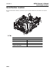
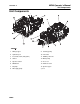
MR90 Operator’s Manual Overview - 4 Unit Components Unit Components 1. Mixing hopper 9. Cleaning pump 2. Hydraulic jack 10. T14 trailer 3. Fresh water tank (300 gallon) 11. FM25h power unit 4. Shaker 12. Water pump 5. Operator station 13. Hose reel 6. MR90 tank 14. Antifreeze tank 7. Pit pump 15. Spoils hopper* 8.
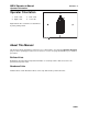
MR90 Operator’s Manual Overview - 5 Operator Orientation Operator Orientation 1. Front of unit 3. Rear of unit 2. Right of unit 4. Left of unit Right and left sides of machine are determined by facing towing vehicle. About This Manual This manual contains information for the proper use of this machine. See the beige Operation Overview pages for basic operating procedures. Cross references such as “See page 50” will direct you to detailed procedures.
Overview - 6 MR90 Operator’s Manual About This Manual CMW®
MR90 Operator’s Manual Foreword - 7 Reporting Safety Defects Foreword This manual is an important part of your equipment. It provides safety information and operation instructions to help you use and maintain your Ditch Witch® equipment. Read this manual before using your equipment. Keep it with the equipment at all times for future reference. If you sell your equipment, be sure to give this manual to the new owner. If you need a replacement copy, contact your Ditch Witch dealer.
MR90 Operator’s Manual Foreword - 8 MR90 Operator’s Manual Issue number 1.0/OM-10/14 Part number 053-2768 Copyright 2014 by The Charles Machine Works, Inc. , Ditch Witch, and CMW are registered trademarks of The Charles Machine Works, Inc. U.S. patents pending.
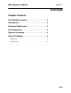
MR90 Operator’s Manual Contents - 9 Contents Overview 1 machine serial number, information about the type of work this machine is designed to perform, basic machine components, and how to use this manual Foreword 5 part number, revision level, and publication date of this manual, and factory contact information Safety 9 machine safety alerts and emergency procedures Controls 17 machine controls, gauges, and indicators and how to use them Prepare 29 procedures for inspecting the jobsite and p
Contents - 10 Appendix additional information about your equipment CMW® MR90 Operator’s Manual 113
MR90 Operator’s Manual Safety - 11 Safety Chapter Contents Guidelines . . . . . . . . . . . . . . . . . . . . . . . . . . . . . . . . 12 Emergency Procedures . . . . . . . . . . . . . . . . . . . . . 13 • Electric Strike Description . . . . . . . . . . . . . . . . . . . . . . . . . . . . . . . . . . . .13 • If an Electric Line is Damaged . . . . . . . . . . . . . . . . . . . . . . . . . . . . . . . .14 • If a Gas Line is Damaged . . . . . . . . . . . . . . . . . . . . . . . . . . . . . . . . . . . .
Safety - 12 MR90 Operator’s Manual Guidelines Guidelines Follow these guidelines before operating any jobsite equipment: • Complete proper training and read operator’s manual before using equipment. • Contact your local One-Call (811 in USA) or the One-Call referral number (888-258-0808 in USA and Canada) to have underground utilities located before digging. Also contact any utilities that do not participate in the One-Call service.
MR90 Operator’s Manual Safety - 13 Emergency Procedures Emergency Procedures Jobsite hazards could cause death or serious injury. Use correct equipment and work methods. Use and maintain proper safety equipment. 274-050 Before operating any equipment, review emergency procedures and check that all safety precautions have been taken. EMERGENCY SHUTDOWN - Turn ignition switch to stop position or push remote engine stop button (if equipped). Electric Strike Description Electric shock.
Safety - 14 MR90 Operator’s Manual Emergency Procedures If an Electric Line is Damaged If you suspect an electric line has been damaged and you are on truck or trailer, DO NOT MOVE. Remain on truck or trailer and take the following actions. The order and degree of action will depend on the situation. • Warn people nearby that an electric strike has occurred. Instruct them to leave the area and contact utility. • Do not allow anyone into area until given permission by utility company.
MR90 Operator’s Manual Safety - 15 Emergency Procedures If a Gas Line is Damaged Fire or explosion possible. Fumes could ignite and cause burns. No smoking, no flame, no spark. 275-419 (2P) Explosion possible. Serious injury or equipment damage could occur. Follow directions carefully. If you suspect a gas line has been damaged, take the following actions. The order and degree of action will depend on the situation. • Immediately shut off engine(s), if this can be done safely and quickly.
Safety - 16 MR90 Operator’s Manual Emergency Procedures If a Fiber Optic Cable is Damaged Do not look into cut ends of fiber optic or unidentified cable. Vision damage can occur. Contact utility company. If Machine Catches on Fire Perform emergency shutdown procedure and then take the following actions. The order and degree of action will depend on the situation. • Immediately move battery disconnect switch (if equipped and accessible) to disconnect position.
MR90 Operator’s Manual Safety - 17 Safety Alert Classifications Safety Alert Classifications These classifications and the icons defined on the following pages work together to alert you to situations which could be harmful to you, jobsite bystanders or your equipment. When you see these words and icons in the book or on the machine, carefully read and follow all instructions. YOUR SAFETY IS AT STAKE. Watch for the three safety alert levels: DANGER, WARNING and CAUTION. Learn what each level means.
MR90 Operator’s Manual Safety - 18 Machine Safety Alerts Machine Safety Alerts Moving parts could cut off hand or foot. Stay away. 1 275-184, 273-437, 273-546 Tiedown location. See Transport chapter for more information. 274-318 2 Lift point. See Transport chapter for more information.
MR90 Operator’s Manual Safety - 19 Machine Safety Alerts 4 5 6 7 Pressurized fluid or air could pierce skin and cause severe injury. Refer to operator’s manual for proper use. 270-6035 Rotating shaft will cause death or serious injury. Stay away. 270-1506 Read operator’s manual. Know how to use all controls. Your safety is at stake. 273-475 Electric shock will cause death or serious injury. Fluid system could become electrified while connected to drilling unit.
Safety - 20 MR90 Operator’s Manual Machine Safety Alerts CMW®
MR90 Operator’s Manual Controls - 21 Controls Chapter Contents Power Unit . . . . . . . . . . . . . . . . . . . . . . . . . . . . . . . 22 Mixing Unit . . . . . . . . . . . . . . . . . . . . . . . . . . . . . . . 30 Recycling Unit . . . . . . . . . . . . . . . . . . . . . . . . . . . . .
MR90 Operator’s Manual Controls - 22 Power Unit Power Unit Controls and Indicators 1. Not used 8. Hydraulic fluid temperature indicator 2. Not used 9. Glow plug indicator 3. Battery indicator 10. Hourmeter 4. Low fuel indicator 11. Cold start button 5. Fuel gauge 12. Throttle 6. Engine oil pressure indicator 13. Auxiliary outlet 7. Coolant temperature indicator 14. Ignition switch Item 1. Not used 2.
MR90 Operator’s Manual Controls - 23 Power Unit Item 3. Description Battery indicator Notes Indicates low battery voltage. c00ic008w.eps 4. Low fuel indicator Displays fuel level near empty. 5. Fuel gauge Displays fuel level in tank. Fuel tank holds 15 gal (56.85 L). NOTICE: Notice: Use ultra low sulfur fuel only. 6. Engine oil pressure indicator Lights when engine oil pressure falls below 8-12 psi (.6-.8 bar). Also lights briefly when engine is started.
MR90 Operator’s Manual Controls - 24 Power Unit Item Description Notes 7. Coolant temperature indicator Lights when engine coolant temperature is over 275°F (135°C). If light remains on: Also, lights briefly when engine is started. • Turn off engine and let unit cool. • Check fan belt tension. • Check for low coolant level. • Check cooling fins for dirt and debris. c00ic232h.eps 8. Hydraulic fluid temperature indicator Lights and alarm sounds when hydraulic fluid is overheating.
MR90 Operator’s Manual Controls - 25 Power Unit Item Description Notes 11. Cold start button To help start cold engine, turn ignition switch to first position. IMPORTANT: Press cold start button according to temperatures below. Press cold start button as directed in notes. • If ambient temperature is below 40°F (4°C), press and hold button for five seconds. • If ambient temperature is below 20°F (-7°C), press and hold button for ten seconds.
MR90 Operator’s Manual Controls - 26 Power Unit Remote Control (optional) 1. Remote control power button 4. Cleaning pump button 2. Remote stop button 5. Mix/supply pump button 3. Pit pump button 6. Not used Item Description Notes 1. Remote control power button To turn remote control module off, press. IMPORTANT: 2. Remote stop button CMW® To stop the engine, press. • Pressing any button will turn the remote on. • Turning the remote off does not shut off pumps.
MR90 Operator’s Manual Controls - 27 Power Unit Item Description Notes 3. Pit pump button To turn pit pump on and off, press. Pit pump control must be engaged for the remote function to work. See “Pit pump/pressure wash pump selector” on page 35. 4. Cleaning pump button To turn cleaning pump on and off, press. Switch at control panel must be on for remote function to work. See “Cleaning pump switch” on page 34. 5. Mix/supply pump button To turn mix/supply pump on and off, press.
MR90 Operator’s Manual Controls - 28 Power Unit Indicators 1. Fluid low warning light 2. Fluid full warning light Item Description Notes 1. Fluid low warning light Amber light will flash when volume of fluid in MR90 tank is too low. IMPORTANT: This light is magnetic and can be moved to ensure better visibility. 2. Fluid full warning light Green light will flash when volume of fluid in dirty side of MR90 tank is full.
MR90 Operator’s Manual Controls - 29 Power Unit Miscellaneous Item Description Battery disconnect switch To connect, move clockwise. Notes To disconnect, move counterclockwise. c00ic654w.
MR90 Operator’s Manual Controls - 30 Mixing Unit Mixing Unit Gauges Hydrocyclone pressure gauge Item Description Notes Hydrocyclone pressure gauge Indicates the pressure of fluid moving through the hydrocyclones. IMPORTANT: • If gauge reads lower than 30-35 psi (2.06-2.41 bar), check hydrocyclones. See “Clean Hydrocyclones” on page 94. • If gauge reads higher than 30-35 psi (2.06-2.41 bar) check the Ystrainer. See“Clean Y-Strainer” on page 79. Gauge should read 30-35 psi (2.06-2.41 bar).
MR90 Operator’s Manual Controls - 31 Mixing Unit Valves 1. Fluid sample valve 4. Venturi jet valve 2. Circulating jet valve 5. Hydrocyclone valve 3. Mix hopper valve 6. Drill supply valve Item Description 1. Fluid sample valve To obtain a sample of drilling fluid for testing, open valve. 2. Circulating jet valve To circulate fluid while mixing, open valve. Notes To stop circulation, close valve. 3. Mixing hopper valve To add drilling additives to hopper, open valve.
MR90 Operator’s Manual Controls - 32 Mixing Unit Item Description Notes 4. Venturi jet valve To allow flow from hopper to mixing venturi, open valve. IMPORTANT: • Open valve only when pouring additives into hopper for mixing. Close valve when finished. • Do not open valve unless pump is running and venturi jet valve is open. Fluid could flow back into hopper. To stop flow from hopper to mixing venturi, close valve. 5. Hydrocyclone valve To allow air flow to operate hydrocyclones, open valve.
MR90 Operator’s Manual Controls - 33 Recycling Unit Recycling Unit Controls 1. Cleaning pump switch 7. Screen left/right tilt control 2. Mix/supply pump switch 8. Spoils hopper mixer control* 3. Pit pump auto control switch 9. Spoils hopper door control* 4. Shaker control 10. Shaker speed control 5. Pit pump/pressure wash pump selector 11. Pit pump speed adjustment control 6.
MR90 Operator’s Manual Controls - 34 Recycling Unit Item Description 1. Cleaning pump switch To turn cleaning pump on, press top. Notes To turn pump off, press bottom. 2. Mix/supply pump switch To turn mix/supply pump on, press top. To turn pump off, press bottom. 3. Pit pump auto control switch To turn pit pump auto control on, press top. To allow manual control, press bottom. 4. Shaker control To start shaker, push lever up. To stop shaker, pull lever back.
MR90 Operator’s Manual Controls - 35 Recycling Unit Item Description Notes 5. Pit pump/pressure wash pump selector To turn pit pump on, push lever up. IMPORTANT: To turn pressure washer pump on, pull lever back. To turn pumps off, center lever. 6. Screen front/rear tilt control • Pit pump lever must be engaged for remote to function. • Do not leave lever pulled back when not using wash wand. Damage may occur. To raise front of screens, push lever up. To lower front of screens, pull lever back.
MR90 Operator’s Manual Controls - 36 Recycling Unit Item Description 9. Spoils hopper door control (optional) To raise door on back of spoils hopper, push lever up. To lower door on back of spoils hopper, pull lever back. 10. Shaker speed control To increase shaker speed, turn counterclockwise. To decrease shaker speed, turn clockwise. 11. Pit pump speed adjustment control To increase pit pump flow, turn clockwise. To decrease pit pump flow, turn counterclockwise.
MR90 Operator’s Manual Controls - 37 Recycling Unit Auxiliary Controls 1. Fresh water transfer pump switch 3. Auxiliary outlet 2. Auxiliary outlet switch Item Description Notes 1. Fresh water transfer pump switch To turn fresh water transfer pump on, press top. Transfers water from 300 gal tank to the MR90 tank. To turn pump off, press bottom.
MR90 Operator’s Manual Controls - 38 Recycling Unit Item Description 2. Auxiliary outlet switch To turn auxiliary outlet on, press top. Notes To turn auxiliary outlet off, press bottom. 3. Auxiliary outlet c00ic179h.eps CMW® To operate work lights or other 12V devices, plug into outlet. Outlet has power only when ignition switch is on.
MR90 Operator’s Manual Controls - 39 Recycling Unit Valves 1. Spoils hopper drain valve* 5. Clean side tank drain valve 2. Antifreeze valve 6. Fresh water control valve 3. Water drain valve 7. Mud flow control valve 4. Dirty side tank drain valve *Optional Item Description 1. Spoils hopper drain valve (optional) To drain spoils hopper, open valve. 2. Antifreeze valve To mix antifreeze into the fresh water pump, open valve. 3.
MR90 Operator’s Manual Controls - 40 Recycling Unit Item Description Notes 6. Fresh water control valve To transfer water from 300 gal tank to MR90 tank, open valve. IMPORTANT: 7. Mud flow control valve To increase mud flow onto screens, move valve toward open. To decrease mud flow onto screens, move valve toward close. CMW® • Turn on with fresh water transfer pump to transfer water to MR90 tank. • Shut off when MR90 tank is full to avoid overflow from dirty side tank into fresh water tank.
MR90 Operator’s Manual Controls - 41 Recycling Unit Trailer Controls 1. Hydraulic trailer jack control 2. Manual trailer jack handle Item Description Notes 1. Hydraulic trailer jack control Push lever down to lower front of trailer. IMPORTANT: Ensure manual trailer jack control is disengaged. Pull lever up to raise front of trailer. 2. Manual trailer jack handle Turn handle clockwise to lower front of trailer. Turn handle counterclockwise to raise front of trailer.
Controls - 42 MR90 Operator’s Manual Recycling Unit CMW®
MR90 Operator’s Manual Prepare - 43 Prepare Chapter Contents Gather Information . . . . . . . . . . . . . . . . . . . . . . . . . 44 • Arrange for Traffic Control . . . . . . . . . . . . . . . . . . . . . . . . . . . . . . . . . . .44 • Prepare for Working Near Existing Utilities . . . . . . . . . . . . . . . . . . . . . .44 • Plan for Emergency Services . . . . . . . . . . . . . . . . . . . . . . . . . . . . . . . . .44 Inspect Jobsite . . . . . . . . . . . . . . . . . . . . . . . . . . . .
Prepare - 44 MR90 Operator’s Manual Gather Information Gather Information A successful job begins before the excavation. The first step in planning is reviewing information already available about the job and jobsite. Arrange for Traffic Control If working near a road or other traffic area, contact local authorities about safety procedures and regulations.
MR90 Operator’s Manual Prepare - 45 Inspect Jobsite Inspect Jobsite • Follow U.S. Department of Labor regulations on excavating and trenching (Part 1926, Subpart P) and other similar regulations. • Contact your local One-Call (811 in USA) or the One-Call referral number (888-258-0808 in USA and Canada) to have underground utilities located before digging. Also contact any utilities that do not participate in the One-Call service.
MR90 Operator’s Manual Prepare - 46 Check Supplies and Prepare Equipment Check Supplies and Prepare Equipment Assemble Accessories Fire Extinguisher If required, mount a fire extinguisher near the power unit but away from possible points of ignition. The fire extinguisher should always be classified for both oil and electric fires. It should meet legal and regulatory requirements.
MR90 Operator’s Manual Transport - 47 Transport Chapter Contents Lift . . . . . . . . . . . . . . . . . . . . . . . . . . . . . . . . . . . . . . 48 • Points . . . . . . . . . . . . . . . . . . . . . . . . . . . . . . . . . . . . . . . . . . . . . . . . . . .48 • Procedure . . . . . . . . . . . . . . . . . . . . . . . . . . . . . . . . . . . . . . . . . . . . . . . .48 Haul . . . . . . . . . . . . . . . . . . . . . . . . . . . . . . . . . . . . .
MR90 Operator’s Manual Transport - 48 Lift Lift Crushing weight. If load falls or moves it could kill or crush you. Use proper procedures and equipment or stay away. Points Lifting points are identified by lifting decals. Lifting at other points is unsafe and can damage machinery. Procedure Tank Use crane capable of supporting the equipment's size and weight. See “Specifications” on page 103 or measure and weigh equipment before lifting.
MR90 Operator’s Manual Transport - 49 Lift Recycling Unit Use crane capable of supporting the equipment's size and weight. See “Specifications” on page 103 or measure and weigh equipment before lifting. Lift recycling unit by attaching lifting device at lift point. IMPORTANT: Empty before lifting.
MR90 Operator’s Manual Transport - 50 Lift Haul Inspect Trailer • Check hitch for wear and cracks. Lubricate if needed. • Check battery for 12V charge. • Inspect lights for cleanliness and correct operation. Inspect reflectors and replace if needed. • Check tire pressure. Check lug nut torque with a torque wrench. • Ensure trailer brakes are adjusted to come on in synchronization with tow vehicle brakes. • Check ramps (if equipped) and trailer bed for cracks. Hitch Trailer 1.
MR90 Operator’s Manual Handle Fluid - 51 Handle Fluid Chapter Contents Mix Fluid . . . . . . . . . . . . . . . . . . . . . . . . . . . . . . . . . 52 • Set Up . . . . . . . . . . . . . . . . . . . . . . . . . . . . . . . . . . . . . . . . . . . . . . . . . . .52 • Mixing Fluid . . . . . . . . . . . . . . . . . . . . . . . . . . . . . . . . . . . . . . . . . . . . . . .52 • Transferring Fluid . . . . . . . . . . . . . . . . . . . . . . . . . . . . . . . . . . . . . . . . . .53 Recycle Fluid. . . . .
MR90 Operator’s Manual Handle Fluid - 52 Mix Fluid Mix Fluid Set Up 1. Position fluid unit and connect to drilling unit. See drilling unit operator’s manual. IMPORTANT: Leave unit hitched to towing vehicle or properly stabilized. 2. Block trailer wheels. Mixing Fluid Jobsite hazards could cause death or serious injury. Use correct equipment and work methods. Use and maintain proper safety equipment.
MR90 Operator’s Manual Handle Fluid - 53 Mix Fluid 8. Close hopper valve and close hopper lid. 9. Mix well. 10. Add liquid additives directly to MR90 tank. IMPORTANT: Pumps must be circulating when adding liquid additives. Transferring Fluid Electric shock. Contacting electric lines will cause death or serious injury. Know location of lines and stay away.
Handle Fluid - 54 MR90 Operator’s Manual Recycle Fluid Recycle Fluid Set Up 1. Position fluid unit and connect to drilling unit. See drilling unit operator’s manual. IMPORTANT: Leave unit hitched to towing vehicle or properly stabilized. 2. Block trailer wheels. Connect Pit Pump 1. Connect hose at 1B and secure other end at 1A. 2. Connect hose at 2B and secure other end at 2A.
MR90 Operator’s Manual Handle Fluid - 55 Recycle Fluid 3. Ensure pit pump is not directly on bottom of pit by suspending it in the pit or digging a shelf for it to sit on (shown).
Handle Fluid - 56 MR90 Operator’s Manual Recycle Fluid Recycling Fluid 1. Level screens left to right. See “Screen left/right tilt control” on page 35. 2. Turn shaker on. 3. Turn on cleaning pump and check that hydrocyclones are operating at 30 psi (2.06 bar). IMPORTANT: MR90 tank should be at least half full before turning on cleaning pump. 4. Turn on pit pump to supply used mud to shaker screens. IMPORTANT: Use auto mode for pit pump to avoid overflowing MR90 tank.
MR90 Operator’s Manual Handle Fluid - 57 Operating in Cold Weather Operating in Cold Weather For successful operation in cold weather, follow these procedures. • Use mix/supply pump to keep drilling fluid circulating at all times, even during transport to and from the jobsite. • Use antifreeze wash pump to mix antifreeze into system. • If possible, use all drilling fluid in MR90 tank before transporting unit.
Handle Fluid - 58 MR90 Operator’s Manual Operating in Cold Weather CMW®
MR90 Operator’s Manual Systems and Equipment - 59 Systems and Equipment Chapter Contents Recommended Products . . . . . . . . . . . . . . . . . . . . 60 • Guidelines . . . . . . . . . . . . . . . . . . . . . . . . . . . . . . . . . . . . . . . . . . . . . . .60 • Polymer . . . . . . . . . . . . . . . . . . . . . . . . . . . . . . . . . . . . . . . . . . . . . . . . .61 • Bentonite . . . . . . . . . . . . . . . . . . . . . . . . . . . . . . . . . . . . . . . . . . . . . . . .61 • Mixtures . . . . .
MR90 Operator’s Manual Systems and Equipment - 60 Recommended Products Recommended Products Improper handling or use of chemicals may result in illness, injury, or equipment damage. Follow instructions on labels and in material safety data sheets (MSDS). Use breathing protection when exposed to silica dust. 270-4952 For productive drilling and equipment protection, use these recommended Baroid® products, available from your Ditch Witch® dealer.
MR90 Operator’s Manual Systems and Equipment - 61 Recommended Products Polymer This drilling fluid additive provides excellent lubrication and increases viscosity in average soils and heavy clay. In swelling clay, polymer can reduce swelling that traps pipe in the bore. There are two types of polymer: • long chain such as Baroid® EZ-Mud Gold NOTICE: Long chain polymer is not recommended for this unit. • medium chain such as Baroid Quik-Trol Bentonite Bentonite is a dry powder.
MR90 Operator’s Manual Systems and Equipment - 62 Recommended Products Mixtures NOTICE: Bentonite does not mix well in water containing polymer. To use both, mix bentonite first, then add polymer. • If chemicals are added in the wrong order, they will not mix properly and will form clumps. • If tank contains bentonite/polymer mix and more drilling fluid is needed, completely empty tank and start with fresh water before mixing another batch. General mixing order 1. Soda ash 2. Bentonite 3.
MR90 Operator’s Manual Systems and Equipment - 63 Recommended Products Soil type Mixture/100 gal (378 L) of water Notes sand, gravel, clay or shale 35 - 40 lb (16-18 kg) Bore-Gel .5lb (227 g) EZ-Mud Gold Vary mixture according to percentage of sand and clay clay .5 lb (225 g) Poly Bore Flow rate should be 3-5 parts fluid to 1 part soil. swelling/sticky clay .75 - 1 lb (340-450 g) EZ-Mud Gold Flow rate should be 3-5 parts fluid to 1 part soil. solid rock (shale) 40 lb (18 kg) Bore-Gel Use .
Systems and Equipment - 64 MR90 Operator’s Manual Drilling Fluid Requirements Drilling Fluid Requirements 1. Determine drilling conditions and choose appropriate drilling fluid mix. 2. Estimate amount of supplies needed and check availability. • Drilling fluid • Water supply. If more water than can be carried with the unit will be needed, arrange to transport additional water. • Bentonite and/or polymer 3. Check water quality. • Use meter or pH test strips to test pH of water. If pH is below 9.
MR90 Operator’s Manual Systems and Equipment - 65 Drilling Fluid Measurements Drilling Fluid Measurements Fluid measurements are important in ensuring the drilling system functions correctly. The viscosity, mud weight, and sand content of drilling fluids must be controlled and can be measured using the drilling fluid test kit (p/n 191-158), available from your Ditch Witch® dealer.
Systems and Equipment - 66 MR90 Operator’s Manual Drilling Fluid Measurements Mud Weight The density of a given liquid is the mud weight. To determine mud weight, you will need the mud balance and scale in your drilling fluid test kit (p/n 191158), available from your Ditch Witch® dealer. IMPORTANT: Make sure all pieces of mud weight kit are clean and free of obstruction before measuring drilling fluid. 1. Place mud balance base on level surface. 2. Fill the cup to the top with mud sample to be weighed.
MR90 Operator’s Manual Systems and Equipment - 67 Screens Screens Use the chart below to determine which set of screens will work best for the soil type at the jobsite. A. Clay B. Silt C. Sand D.
Systems and Equipment - 68 MR90 Operator’s Manual Screens CMW®
MR90 Operator’s Manual Complete the Job - 69 Complete the Job Chapter Contents Dispose of Fluid . . . . . . . . . . . . . . . . . . . . . . . . . . . 70 Rinse Equipment . . . . . . . . . . . . . . . . . . . . . . . . . . 70 Disconnect . . . . . . . . . . . . . . . . . . . . . . . . . . . . . . . 72 Stow Tools . . . . . . . . . . . . . . . . . . . . . . . . . . . . . . . . 72 Storage. . . . . . . . . . . . . . . . . . . . . . . . . . . . . . . . . . .
MR90 Operator’s Manual Complete the Job - 70 Dispose of Fluid Dispose of Fluid Moving parts could cut off hand or foot. Stay away. 275-184 To help avoid injury: Never place hands through spoils door unless engine is off and battery is disconnected. Rotating shaft will cause death or serious injury. Stay away. 270-1506 To help avoid injury: Leave cover on spoils hopper. Dispose of unneeded fluid and waste products using one of the methods described below. 1.
MR90 Operator’s Manual Complete the Job - 71 Rinse Equipment Rinse Equipment Pressurized fluid or air could pierce skin and cause severe injury. Refer to operator’s manual for proper use. 270-6035 Spray water onto equipment to remove dirt and mud. Hose reel is equipped with a handle restraint (shown). • Pull latch forward and lift handle up to release. • Pull latch forward and push handle down to secure.
Complete the Job - 72 MR90 Operator’s Manual Disconnect Disconnect Disconnect and store hoses and cables. Stow Tools Make sure hoses, drilling fluid measurement kit, and other tools are properly stowed. Stow pit pump as shown. Storage Drain tank and ensure all fluid system valves are open. Also open drain valve on pump.
MR90 Operator’s Manual Service - 73 Service Chapter Contents Service Precautions . . . . . . . . . . . . . . . . . . . . . . . . 74 • Welding Precaution . . . . . . . . . . . . . . . . . . . . . . . . . . . . . . . . . . . . . . . .74 • Washing Precaution . . . . . . . . . . . . . . . . . . . . . . . . . . . . . . . . . . . . . . . .74 Recommended Lubricants/Service Key . . . . . . . . 75 • Engine Oil Temperature Chart . . . . . . . . . . . . . . . . . . . . . . . . . . . . . . . .
MR90 Operator’s Manual Service - 74 Service Precautions Service Precautions Incorrect procedures could result in death, injury, or property damage. Learn to use equipment correctly. To help avoid injury: • Unless otherwise instructed, all service should be performed with engine off. • Refer to engine manufacturer’s manual for engine maintenance instructions. Welding Precaution NOTICE: Welding can damage electronics. • Welding currents can damage electronic components.
MR90 Operator’s Manual Service - 75 Recommended Lubricants/Service Key Recommended Lubricants/Service Key Item Description DEO Diesel engine oil meeting or exceeding CH-4 per the API service classification or E5 per the European Automobile Manufacturer’s Association (ACEA) and SAE viscosity recommended by engine manufacturer (SAE 10W30) MPG Multipurpose grease meeting ASTM D217 and NLGI 1 THF Tractor hydraulic fluid, similar to Phillips 66® HG, Mobilfluid® 423, Chevron® Tractor Hydraulic Fluid, Tex
MR90 Operator’s Manual Service - 76 Recommended Lubricants/Service Key Engine Oil Temperature Chart Temperature range anticipated before next oil change Approved Coolant This unit was filled with John Deere® Cool-Gard® coolant before shipment from factory. Add only CoolGard (p/n 255-006) or any fully-formulated, ethylene glycol based, low-silicate, heavy-duty diesel engine coolant meeting ASTM specification D5345 (prediluted) or D4985 (concentrate).
MR90 Operator’s Manual Service - 77 Recommended Lubricants/Service Key Approved Fuel Avoid static electricity when fueling. Ultra Low Sulfur Diesel (ULSD) poses a greater static ignition hazard than earlier diesel formulations. Avoid death or serious injury from fire or explosion. Consult with your fuel system supplier to ensure the delivery system is in compliance with fueling standards for proper grounding and bonding practices. The engine is this unit is designed to run on diesel fuel.
MR90 Operator’s Manual Service - 78 10 Hour 10 Hour Location Task Recycling Unit Clean screens Notes Clean Y-strainer Clean pit pump Check coolant level DEAC Check engine oil level DEO Check water pump oil level NDO Clean water pump filter Check radiator Check hydraulic hoses Trailer Check tire pressure and lug nut torque Check tail lights and reflectors Check hitch bolts Recycling Unit Clean Screens Clean screens every 10 hours, after each use, and as needed. 1.
MR90 Operator’s Manual Service - 79 10 Hour Clean Y-Strainer Remove Y-strainer and clean every 10 hours. Clean Pit Pump Spray pit pump with wash wand every 10 hours or after each use. Check Coolant Level Check coolant level every 10 hours. Add coolant at cap (shown) as needed to maintain level between LOW and FULL on overflow tank.
Service - 80 MR90 Operator’s Manual 10 Hour Check Engine Oil Level Check engine oil level at dipstick (1) every 10 hours. Add DEO at fill (2) as needed to maintain oil level at highest line on dipstick. See “Approved Coolant” on page 76. Check Water Pump Oil Level With frame level, check water pump oil at sight glass (2) every 10 hours. Add NDO at fill (1) as necessary to keep oil at halfway mark on sight glass.
MR90 Operator’s Manual Service - 81 10 Hour Clean Water Pump Filter Clean water pump filter every 10 hours and replace as needed. 1. Open filter housing. 2. Remove element and rinse housing thoroughly with water. 3. Inspect element for signs of collapse and for brittle or broken rubber seals on the ends of the element. Replace as needed. 4. Replace element and close filter housing. Check Radiator Check radiator for dirt, grass, and other foreign matter every 10 hours.
MR90 Operator’s Manual Service - 82 10 Hour Check Hydraulic Hoses Pressurized fluid or air could pierce skin and cause severe injury. Refer to operator’s manual for proper use. 270-6035 To help avoid injury: • Before disconnecting a hydraulic line, turn engine off and operate all controls to relieve pressure. Lower, block, or support any raised component with a hoist. Cover connection with heavy cloth and loosen connector nut slightly to relieve residual pressure. Catch all fluid in a container.
MR90 Operator’s Manual Service - 83 10 Hour Trailer Check Trailer Tire Pressure and Lug Nut Torque Check tire pressure (2) and lug nut (1) torque every ten hours. See below for correct pressure and torque. To verify trailer model, see the certification plate located on the trailer tongue. Trailer Pressure Torque T14R 80 psi (5.5 bar) 90-120 ft•lb (122-163 N•m) Check Trailer Lights and Reflectors Check lights and reflectors for correct operation and cleanliness every 10 hours. j33om013h.
MR90 Operator’s Manual Service - 84 50 Hour 50 Hour Location Task Notes Recycling Unit Change water pump oil NDO, initial Check air filter Change engine oil and filter Initial, DEO Lube pump Change shaker gearbox oil MPL Change hydraulic fluid filter initial Recycling Unit Change Water Pump Oil Change oil after the first 50 hours of operation initially, and every 450 hours thereafter. Change oil more frequently if working in dusty conditions. 1. Drain at plug (3) while oil is warm. 2.
MR90 Operator’s Manual Service - 85 50 Hour Change Engine Oil and Filter (Initial) Change engine oil after the first 50 hours and every 150 hours thereafter, while oil is warm and with unit parked on level ground. 1. Open drain (3). 2. Replace filter (4). 3. Close drain. 4. Add approximately 4.2 qt (4 L) DEO at fill (2) until oil level is at highest line on dipstick (1). Lube Pump Lube zerk (2) with MPG every 50 hours. Grease cavity is full when grease escapes from grease cylinder relief valve (1).
Service - 86 MR90 Operator’s Manual 50 Hour Change Hydraulic Fluid Filter Replace hydraulic fluid filter (shown) after the first 50 hours, and every 900 hours thereafter.
MR90 Operator’s Manual Service - 87 150 Hour 150 Hour Location Task Recycling Unit Change fuel filters Notes Check fan belt tension Change engine oil and filter Recycling Unit Change Fuel Filters Change fuel filter (1) and in-line fuel filter (2) every 150 hours. 1. Remove filters. 2. Fill new filter with clean fuel. 3. Apply fuel oil over the gasket and hand-tighten. Check Fan Belt Tension Check fan belt tension every 150 hours. 1. Turn off engine and remove key. 2.
Service - 88 MR90 Operator’s Manual 150 Hour Change Engine Oil and Filter Change engine oil every 150 hours while oil is warm and with unit parked on level ground. 1. Open drain (3). 2. Drain crankcase while oil is warm. 3. Replace filter (4). 4. Close drain. 5. Add approximately 4.2 qt (4 L) DEO at fill (2) until oil level is at highest line on dipstick (1).
MR90 Operator’s Manual Service - 89 300 Hour 300 Hour Location Task Recycling Unit Change air filter Notes Recyling Unit Change Air Filter Change air filter every 300 hours. 1. Open air filter housing at latches (1). 2. Remove primary (3) and secondary (2) elements. 3. Wipe inside of housing and wash end cap. 4. Insert new primary and secondary elements. 5. Close air filter case.
MR90 Operator’s Manual Service - 90 450 Hour 450 Hour Location Task Recycling Unit Replace fan belt Replace pump drive belt Change water pump oil NDO Change shaker gearbox oil MPL Recycling Unit Replace Fan Belt Replace fan belt (shown) every 450 hours. To replace 1. Loosen bolts (1, 2) and remove belt. 2. Install new belt and adjust properly. See page 93. Replace Pump Drive Belt Replace pump drive belt (shown) every 450 hours. To replace 1. Loosen bolts (1, 2) and remove belt. 2.
MR90 Operator’s Manual Service - 91 450 Hour Change Water Pump Oil Change oil every 450 hours. Change oil more frequently if working in dusty conditions. 1. Drain at plug (3) while oil is warm. 2. Add approximately 1 qt (.95 L) NDO at fill (1) until oil is at halfway mark on sight glass (2). Change Shaker Gearbox Oil Change shaker gearbox oil every 450 hours. To change: 1. Remove drain plug (2). 2. Drain oil and replace plug. 3. Add MPL at fill (1) until cold oil is halfway up sight glass (3).
Service - 92 MR90 Operator’s Manual 900 Hour 900 Hour Recycling Unit Change Hydraulic Fluid and Filter Change hydraulic fluid and filter yearly or every 900 hours. 1. Drain hydraulic fluid (3), add THF at hydraulic fluid fill (1) until level is midway at sight glass (4). 2. Replace filter (2). 1800 Hour Recycling Unit Change Engine Coolant Drain cooling system at drain (2). Add approved coolant at fill (1) every two years or 1800 hours.
MR90 Operator’s Manual Service - 93 As Needed As Needed Location Task Recycling Unit Adjust fan belt Notes Adjust pump drive belt Clean hydrocyclones Change remote batteries Change screens Check battery Recycling Unit Adjust Fan Belt Adjust fan belt as needed. 1. Turn off engine and remove key. 2. Apply moderate thumb pressure to belt between pulleys where shown. Belt is properly tensioned when deflection is about 1/4-3/8” (6-10 mm). 3.
Service - 94 MR90 Operator’s Manual As Needed Clean Hydrocyclones Clean hydrocyclones as needed. Remove bottom of hydrocyclone and clean out dirt and debris. Change Remote Batteries IMPORTANT: Do not mix new and used batteries. Do not mix battery brands or types. Replace remote batteries as needed, using three AA-cell alkaline batteries. 1. Remove battery cap. 2. Insert batteries as shown. 3. Replace battery cap. 4. Check operation.
MR90 Operator’s Manual Service - 95 As Needed Change Screens Change screens as needed. 1. Pin access flaps (3) back to expose screens. 2. Remove upper screen (1) by tapping wedges with hammer. IMPORTANT: Remove screens from the back of the unit. 3. Remove lower screen (2) by tapping wedges with hammer. 4. Replace screens and wedges. IMPORTANT: Screens are not interchangeable. Check Battery Check battery as needed. Keep battery clean and terminals free of corrosion. To clean: 1.
MR90 Operator’s Manual Service - 96 As Needed Charge Battery Explosion possible. Serious injury or equipment damage could occur. Follow directions carefully. To help avoid injury: • Use a single 12V maximum source for charging. Do not connect to rapid chargers or dual batteries. • Use caution and wear personal protective equipment such as safety eyewear, when charging or cleaning battery. • Keep sparks, flames, and any ignition source away from batteries at all times.
MR90 Operator’s Manual Service - 97 As Needed Charging Procedure (Engine Off) 1. Park service vehicle close to disabled equipment but do not allow vehicles to touch. Engage parking brake in both vehicles. 2. Turn the ignition switch to the OFF position in both vehicles, and turn off all electrical loads. Disconnect the machine controller. 3. Inspect battery in disabled vehicle (B) for signs of cracking, bulging, leaking, or other damage.
MR90 Operator’s Manual Service - 98 200 Mile 200 Mile Location Task Notes Trailer Adjust electric brakes initial Trailer Adjust Electric Brakes Adjust brakes after 200 miles (300 km) initially. 1. Place adequate jack stands under frame rails and remove wheels. 2. Remove cover from adjusting slot on bottom of backing plate. 3. Rotate adjuster starwheel with screwdriver or brake spoon to expand brake shoes. Adjust until drum is very difficult to turn by hand. 4.
MR90 Operator’s Manual Service - 99 3000 Mile 3000 Mile Location Task Trailer Adjust electric brakes Notes Trailer Adjust Electric Brakes Adjust brakes every 3000 miles (5000 km). 1. Place adequate jack stands under frame rails and remove wheels. 2. Remove cover from adjusting slot on bottom of backing plate. 3. Rotate adjuster starwheel with screwdriver or brake spoon to expand brake shoes. Adjust until drum is very difficult to turn by hand. 4.
MR90 Operator’s Manual Service - 100 12,000 Mile 12,000 Mile Location Task Trailer Inspect brake shoes and linings Inspect and lube axle bearings Trailer Inspect Brake Shoes and Linings Inspect shoes and linings every 12 months or 12,000 miles (20 000 km) for wear. When lining is worn to 1/16” (2 mm) or less, replace linings. Replace shoe and lining if contaminated by oil.
MR90 Operator’s Manual Service - 101 12,000 Mile Adjust and Lubricate Bearings 1. Place adequate jack stands under frame rails and remove wheels. 2. Unscrew grease cap (11) while holding the hub stationary. 3. Bend locking tang (14) down from outer spindle nut (13) and remove spindle nut (3). 4. Remove tang washer, unscrew inner spindle nut and remove spindle washer (16). 5. Remove hub from spindle. Do not drop outer bearing cone. 6. Pry seal (2) from hub and remove inner bearing cone (3). 7.
Service - 102 MR90 Operator’s Manual 12,000 Mile CMW®
MR90 Operator’s Manual Specifications - 103 Specifications Dimensions U.S. Metric L Length, T14R trailer 216 in 5.48 m H Height 109 in 2.77 m W Width (as shown; variable with layout flexibility) 100 in 2.54 m A Screen angle 8° 8° A2 Screen level angle +5° to -5° +5° to -5° Weight, dry 3450 lb 1570 kg System weight, with fluid (990 gal/3750 L per tank) 13065 lb 5926 kg Weight: recycler and water tank U.S.
Specifications - 104 Engine MR90 Operator’s Manual U.S. Metric Kubota® D1105, diesel Cooling medium water Injection indirect Aspiration natural Number of cylinders 3 Displacement 68.5 in3 1.12 L Bore 3.07 in 78.0 mm Stroke 3.09 in 78.4 mm Manufacturer’s gross power (per SAE J1995) 24.8 hp 18.5 kW Estimated net power rating (per SAE J1349) 21.6 hp 16.1 kW Rated speed 3000 rpm 3000 rpm Performance U.S.
MR90 Operator’s Manual Specifications - 105 Fluid Capacities U.S. Metric Engine oil with filter 4.2 qt 4L Fuel tank 15 gal 18.9 L MR90 tank total 445 gal 1685 L Hydraulic reservoir 8.0 gal 30.2 L MR90 tank dirty side 339 gal 1283 L MR90 tank clean side 106 gal 401 L Water tank 300 gal 1135 L Water Pump System U.S. Metric Maximum pressure 2500 psi 207 bar Flow 3 gpm 15.1 L/min Hose reel capacity (locking) 50 ft 15.
Specifications - 106 T14R Trailer MR90 Operator’s Manual U.S. Metric Clearance at jack foot pad 12 in 305 mm Adj. coupler height 18-24 in 457-610 mm Width between fenders 76 in 1.9 m Width outside fenders 96 in 2.4 m Number of axles 2 Coupler (square mount drawbar) 3 in or 2.5 in Type of brakes electric Lug nut torque 90-120 ft•lb 122-163 N•m Hitch bolt torque 260 ft•lb 352 N•m Electrical system 12V DC LT215/85R16 load range E 80 psi 5.
MR90 Operator’s Manual Support - 107 Procedure Support Procedure Notify your dealer immediately of any malfunction or failure of Ditch Witch® equipment. Always give model, serial number, and approximate date of your equipment purchase. This information should be recorded and placed on file by the owner at the time of purchase. Return damaged parts to dealer for inspection and warranty consideration if in warranty time frame.
MR90 Operator’s Manual Warranty - 108 Warranty Ditch Witch® Equipment and Replacement Parts Limited Warranty Policy Subject to the limitation and exclusions herein, free replacement parts will be provided at any authorized Ditch Witch dealership for any Ditch Witch equipment or parts manufactured by The Charles Machine Works, Inc. (CMW) that fail due to a defect in material or workmanship within one (1) year of first commercial use.
MR90 Operator’s Manual Service Record - 111 Service Record Service Performed Date Hours CMW®
Service Record - 112 Service Performed CMW® MR90 Operator’s Manual Date Hours
MR90 Operator’s Manual Appendix - 113 Appendix Chapter Contents Tire Safety Information CMW®
TIRE SAFETY INFORMATION 1.1. STEPS FOR DETERMINING CORRECT LOAD LIMIT – TRAILER Determining the load limits of a trailer includes more than understanding the load limits of the tires alone. On all trailers there is a Federal certification/VIN label that is located on the forward half of the left (road) side of the unit. This certification/VIN label will indicate the trailer’s Gross Vehicle Weight Rating (GVWR). This is the most the fully loaded trailer can weigh.
The Tire Information Placard is attached adjacent to or near the trailer’s VIN (Certification) label at the left front of the trailer. 1.1.2. TRAILERS OVER 10,000 POUNDS GVWR (NOTE: These trailers are not required to have a tire information placard on the trailer.) 1. Determine the empty weight of your trailer by weighing the trailer using a public scale or other means. This step does not have to be repeated. 2.
Innerliner separation - the parting of the innerliner from cord material in the carcass. Light truck (LT) tire - a tire designated by its manufacturer as primarily intended for use on lightweight trucks or multipurpose passenger vehicles. Load rating - the maximum load that a tire is rated to carry for a given inflation pressure. Maximum load rating - the load rating for a tire at the maximum permissible inflation pressure for that tire.
1.4. TIRE SAFETY - EVERYTHING RIDES ON IT The National Traffic Safety Administration (NHTSA) has published a brochure (DOT HS 809 361) that discusses all aspects of Tire Safety, as required by CFR 575.6. This brochure is reproduced in part below. It can be obtained and downloaded from NHTSA, free of charge, from the following web site: http://www.nhtsa.dot.gov/cars/rules/TireSafety/ridesonit/tires_index.
1.5.2. UNDERSTANDING TIRE PRESSURE AND LOAD LIMITS Tire inflation pressure is the level of air in the tire that provides it with load-carrying capacity and affects the overall performance of the trailer. The tire inflation pressure is a number that indicates the amount of air pressure– measured in pounds per square inch (psi) or kilopascals (kpa) –a tire requires to be properly inflated.
1.5.5. TIRE SIZE To maintain tire safety, purchase new tires that are the same size as the trailer's original tires or another size recommended by the manufacturer. Look at the tire information placard, the owner's manual, or the sidewall of the tire you are replacing to find this information. If you have any doubt about the correct size to choose, consult with your dealer. 1.5.6.
1.5.9.2. Information on Light Truck Tires Please refer to the diagram below. Tires for light trucks have other markings besides those found on the sidewalls of passenger tires. LT - indicates the tire is for light trucks or trailers. ST - indicates the tire is for trailer use only. Max. Load Dual kg (lbs) at kPa (psi) Cold - indicates the maximum load and tire pressure when the tire is used as a dual, that is, when four tires are put on each axle. Max.