JT9 Operator’s Manual CMW® Issue 1.
JT9 Operator’s Manual Overview - 1 Overview Chapter Contents Serial Number Location . . . . . . . . . . . . . . . . . . . . . . 2 Intended Use . . . . . . . . . . . . . . . . . . . . . . . . . . . . . . . 3 Unit Components . . . . . . . . . . . . . . . . . . . . . . . . . . . 4 Operator Orientation. . . . . . . . . . . . . . . . . . . . . . . . . 5 About This Manual . . . . . . . . . . . . . . . . . . . . . . . . . . 5 • Bulleted Lists. . . . . . . . . . . . . . . . . . . . . . . . . . . . . . . . . . .
JT9 Operator’s Manual Overview - 2 Serial Number Location Serial Number Location Record serial numbers and date of purchase in spaces provided. Drilling unit serial number is located as shown.
JT9 Operator’s Manual Overview - 3 Intended Use Intended Use The JT9 is a self-contained horizontal directional drilling unit designed to install buried cable and pipe at distances to 300’ (90 m) depending on soil conditions and is intended for operation in ambient temperatures from 0° to 115°F (-18° to 46°C). Use in any other way is considered contrary to the intended use. The JT9 can be used with Ditch Witch® drilling fluid units and Ditch Witch locating equipment.
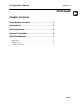
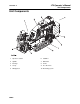
JT9 Operator’s Manual Overview - 4 Unit Components Unit Components 1. Operator’s station 6. Stabilizer 2. Spindle 7. Drill frame 3. Carriage 8. Tracks 4. Set up 9. Vise wrenches 5. Drill pipe box 10.
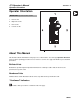
JT9 Operator’s Manual Overview - 5 Operator Orientation Operator Orientation IMPORTANT: Top view of unit is shown. 1. Front of unit 2. Right side of unit 3. Rear of unit 4. Left side of unit About This Manual This manual contains information for the proper use of this machine. See the beige Operation Overview pages for basic operating procedures. Cross references such as “See page 50” will direct you to detailed procedures.
Overview - 6 JT9 Operator’s Manual About This Manual CMW®
JT9 Operator’s Manual Foreword - 7 Foreword This manual is an important part of your equipment. It provides safety information and operation instructions to help you use and maintain your Ditch Witch® equipment. Read this manual before using your equipment. Keep it with the equipment at all times for future reference. If you sell your equipment, be sure to give this manual to the new owner. If you need a replacement copy, contact your Ditch Witch dealer.
JT9 Operator’s Manual Foreword - 8 JT9 Operator’s Manual This manual covers the following models: JT9 Tier 4i, JT9 Tier 4. Issue number 1.0/OM-04/14 Part number 053-2747 Copyright 2014 by The Charles Machine Works, Inc. , Ditch Witch, CMW, Jet Trac, Fluid Miser, Power Pipe, and Pierce Airrow are registered trademarks of The Charles Machine Works, Inc. This product is covered by one or more of the following patents: U.S.
JT9 Operator’s Manual Contents - 9 Contents Overview 1 machine serial number, information about the type of work this machine is designed to perform, basic machine components, and how to use this manual Foreword 7 part number, revision level, and publication date of this manual, and factory contact information Safety 11 machine safety alerts and emergency procedures Controls 21 machine controls, gauges, and indicators and how to use them Operation Overview 41 an overview for completing a job
Contents - 10 JT9 Operator’s Manual Specifications 155 machine specifications including weights, measurements, power ratings, and fluid capacities Support 159 the warranty policy for this machine, and procedures for obtaining warranty consideration and training Service Record a record of major service performed on the machine CMW® 163
JT9 Operator’s Manual Safety - 11 Safety Chapter Contents Guidelines . . . . . . . . . . . . . . . . . . . . . . . . . . . . . . . . 12 Emergency Procedures . . . . . . . . . . . . . . . . . . . . . 13 • Electric Strike Description . . . . . . . . . . . . . . . . . . . . . . . . . . . . . . . . . . . 13 • If an Electric Line is Damaged . . . . . . . . . . . . . . . . . . . . . . . . . . . . . . . 14 • If a Gas Line is Damaged . . . . . . . . . . . . . . . . . . . . . . . . . . . . . . . . . . .
Safety - 12 JT9 Operator’s Manual Guidelines Guidelines Follow these guidelines before operating any jobsite equipment: • Complete proper training and read operator’s manual before using equipment. • Contact your local One-Call (811 in USA) or the One-Call referral number (888-258-0808 in USA and Canada) to have underground utilities located before digging. Also contact any utilities that do not participate in the One-Call service.
JT9 Operator’s Manual Safety - 13 Emergency Procedures Emergency Procedures Jobsite hazards could cause death or serious injury. Use correct equipment and work methods. Use and maintain proper safety equipment. Before operating any equipment, review emergency procedures and check that all safety precautions have been taken. EMERGENCY SHUTDOWN - Turn ignition switch to stop position or push remote engine stop button (if equipped). Electric Strike Description Electric shock.
Safety - 14 JT9 Operator’s Manual Emergency Procedures If an Electric Line is Damaged If you suspect an electric line has been damaged and you are on drilling unit or bonded equipment, DO NOT MOVE. Remain on drilling machine and take the following actions. The order and degree of action will depend on the situation. • Warn people nearby that an electric strike has occurred. • Have someone contact electric company. • Reverse drilling direction and try to break contact.
JT9 Operator’s Manual Safety - 15 Emergency Procedures If a Gas Line is Damaged Fire or explosion possible. Fumes could ignite and cause burns. No smoking, no flame, no spark. Explosion possible. Serious injury or equipment damage could occur. Follow directions carefully. If you suspect a gas line has been damaged, take the following actions. The order and degree of action will depend on the situation. • Immediately shut off engine(s), if this can be done safely and quickly.
Safety - 16 JT9 Operator’s Manual Emergency Procedures If a Fiber Optic Cable is Damaged Do not look into cut ends of fiber optic or unidentified cable. Vision damage can occur. Contact utility company. If Machine Catches on Fire Perform emergency shutdown procedure and then take the following actions. The order and degree of action will depend on the situation. • Immediately move battery disconnect switch (if equipped and accessible) to disconnect position.
JT9 Operator’s Manual Safety - 17 Safety Alert Classifications Safety Alert Classifications These classifications and the icons defined on the following pages work together to alert you to situations which could be harmful to you, jobsite bystanders or your equipment. When you see these words and icons in the book or on the machine, carefully read and follow all instructions. YOUR SAFETY IS AT STAKE. Watch for the three safety alert levels: DANGER, WARNING and CAUTION. Learn what each level means.
JT9 Operator’s Manual Safety - 18 Machine Safety Alerts Machine Safety Alerts Tiedown location. See Transport chapter for more information. 1 Read operator’s manual. Know how to use all 2 controls before operating machine. When you see this sign on the machine or in the manual, read it and use caution. Your safety is at stake. Moving parts could cut off hand or foot. Stay away.
JT9 Operator’s Manual Safety - 19 Machine Safety Alerts Turning shaft will kill you or crush arm or leg. Stay 4 away. Do not park machine on slope unless chocked or 5 blocked. Electric shock will cause death or serious injury. 6 7 Stay away. Moving tools will kill or injure. Never use pipe wrenches on drill string. Fire or explosion possible. Do not use starter fluid. 8 Hot parts may cause burns. Do not touch until cool 9 or wear gloves.
Safety - 20 JT9 Operator’s Manual Machine Safety Alerts CMW®
JT9 Operator’s Manual Controls - 21 Controls Chapter Contents Set-Up Console . . . . . . . . . . . . . . . . . . . . . . . . . . . 22 Left Control Console . . . . . . . . . . . . . . . . . . . . . . . 25 Gauge Cluster . . . . . . . . . . . . . . . . . . . . . . . . . . . . 28 Right Control Console . . . . . . . . . . . . . . . . . . . . . . 32 Anchoring System Console . . . . . . . . . . . . . . . . . 34 Seat/Armrest . . . . . . . . . . . . . . . . . . . . . . . . . . . . . . 36 Battery . . . . . . . . .
JT9 Operator’s Manual Controls - 22 Set-Up Console Set-Up Console 1. Left track control 4. Tracker control key 2. Right track control 5. Engine throttle control 3. Stabilizer and frame tilt control 6. Engine stop Item Description 1. Left track control To move forward, push. To move backward, pull. To stop, move to center. c00ic147h.
JT9 Operator’s Manual Controls - 23 Set-Up Console Item Description 2. Right track control To move forward, push. Notes To move backward, pull. To stop, move to center. c00ic148h.eps 3. Stabilizer and frame tilt control To raise stabilizer and increase frame tilt, push. Note: Stabilizer control lowers the front of the drill frame along with the stabilizer. To lower stabilizer and decrease frame tilt, pull. 4.
JT9 Operator’s Manual Controls - 24 Set-Up Console Item Description 5. Engine throttle control (Tier 4i) To increase engine speed, push up. Notes To decrease engine speed, pull down. Engine throttle control (Tier 4) To increase speed, press top. To decrease speed, press bottom. To further increase or decrease speed, press additional times. c00ic243h.eps 6. Engine stop CMW® To stop engine, press.
JT9 Operator’s Manual Controls - 25 Left Control Console Left Control Console Drilling/Operation Controls 1. Auxiliary outlet 5. Wrench control 2. Ignition switch 6. Rear home/front home switch 3. Engine throttle control 7. Fluid flow control 4. Cold start Item Description Notes 1. Auxiliary outlet Provides power for other equipment. Power output is 12V, 5A.
JT9 Operator’s Manual Controls - 26 Left Control Console Item Description 2. Ignition switch To start engine, insert key and turn clockwise. To stop engine, turn key counterclockwise. 3. Engine throttle control (Tier 4i) To increase engine speed, push up. To decrease engine speed, pull down. Engine throttle control (Tier 4) To increase speed, press top. To decrease speed, press bottom. To further increase or decrease speed, press additional times. c00ic243h.eps 4.
JT9 Operator’s Manual Controls - 27 Left Control Console Item Description 5. Wrench control To clamp front wrench and shut off drilling fluid, move toward pipe box. Notes To unclamp front wrench, move away from pipebox. To clamp and rotate rear (rotating) wrench, move toward engine compartment. To unclamp rear (rotating) wrench, move toward seat. 6. Rear home/ front home switch To move carriage to front of drill frame, press top. To move carriage to rear of drill frame, press bottom. 7.
JT9 Operator’s Manual Controls - 28 Left Control Console Engine Display 1. Hydraulic fluid temperature indicator 7. Engine temperature indicator 2. Hydraulic filter service indicator 8. Engine oil pressure indicator 3. Hourmeter 9. Diagnostics menu indicator 4. Cold start wait indicator 10. Settings menu indicator 5. High temperature indicator 11. Voltmeter display 6. Engine shutdown indicator (Tier 4i) Diagnostic message indicator (Tier 4) 12.
JT9 Operator’s Manual Controls - 29 Left Control Console Item Description Notes 1. Hydraulic fluid temperature indicator Indicates hydraulic fluid is overheating. • Check hydraulic fluid level. • Check cooler for debris. See page 140. 2. Hydraulic filter service indicator Indicates hydraulic fluid filter needs replacing. Change filter when indicator lights continuously and as indicated on page 147. 3. Hourmeter Displays engine operating time. Use engine operating times to schedule service.
JT9 Operator’s Manual Controls - 30 Left Control Console Item Description Notes 5. High temperature indicator Indicates engine is overheating. IMPORTANT: Alarms will sound when engine overheats. Stop engine and service unit. c00ic232h.eps 6. Engine shutdown indicator (Tier 4i) Diagnostic message indicator (Tier 4) Tier 4i: Indicates the engine shutdown relay has been activated due to low engine oil pressure. Tier 4: Indicates a Diagnostic Trouble Code. 7.
JT9 Operator’s Manual Controls - 31 Left Control Console Item Description 9. Diagnostics menu indicator Use soft key directly below icon to access diagnostics menu. 10. Settings menu indicator Use soft key directly below icon to access main menu. 11. Voltmeter display Shows system voltage. Notes c00ic008w.eps 12. Fuel gauge Displays fuel level in tank. NOTICE: Use low sulfur or ultra low sulfur fuel only. Refer to engine operator’s manual for cold weather fuel recommendations.
JT9 Operator’s Manual Controls - 32 Right Control Console Right Control Console 1. Carriage control 4. Thrust pressure gauge 2. Pipe lubricator button (optional) 5. Rotation pressure gauge 3. Drilling fluid pressure gauge Item Description 1. Carriage control To move carriage forward, push. To move carriage backward, pull. To rotate spindle counterclockwise (breakout), move right. To rotate spindle clockwise (makeup), move left.
JT9 Operator’s Manual Controls - 33 Right Control Console Item Description 2. Pipe lubricator button (optional) To apply joint compound to threads at wrenches, press button. 3. Drilling fluid pressure gauge Displays drilling fluid pressure supplied by drilling fluid pump. Notes c00ic157h.eps 4. Thrust pressure gauge Displays hydraulic fluid pressure to thrust motor during thrust and pullback. Estimates thrust and pullback force on lines outside gauge. 5.
JT9 Operator’s Manual Controls - 34 Anchoring System Console Anchoring System Console 1. Left rotation control 3. Right rotation control 2. Left thrust control 4. Right thrust control Item Description Notes 1. Left rotation control To drive anchor, push down. IMPORTANT: Stand on platform when operating anchor controls. To remove anchor, pull up.
JT9 Operator’s Manual Controls - 35 Anchoring System Console Item Description Notes 2. Left thrust control To move anchor down, push down. IMPORTANT: Stand on platform when operating anchor controls. To move anchor up, pull up. 3. Right rotation control To drive anchor, push down. IMPORTANT: Stand on platform when operating anchor controls. To remove anchor, pull up. 4. Right thrust control To move anchor down, push down. IMPORTANT: Stand on platform when operating anchor controls.
JT9 Operator’s Manual Controls - 36 Seat/Armrest Seat/Armrest 1. Seat tilt latch 2. Seat leveling wheel Item Description 1. Seat tilt latch To tilt seat forward for transport, push knob. To lower seat for operation, pull knob. 2. Seat leveling wheel CMW® To level seat when the unit is set up on a side slope, turn wheel.
JT9 Operator’s Manual Controls - 37 Battery Battery 1. Battery disconnect switch Item Description 1. Battery disconnect switch To disable battery power, move switch to the disconnect position. Notes To enable battery power, move switch to the connect position.
JT9 Operator’s Manual Controls - 38 ESID ESID 2 3 1 4 5 6 7 8 j07om042h.eps 1. Alphanumeric display 5. Current problem indicator 2. Strike indicator 6. OK indicator 3. Alarm interrupt button 7. Electrical power supply indicator 4. Voltage problem indicator 8. Self test button Item Description 1. Alphanumeric display Display amount of current and voltage being detected as a percentage of strike condition.
JT9 Operator’s Manual Controls - 39 ESID Item Description Notes 3. Alarm interrupt button To turn off strike alarm at drilling unit, press. 4. Voltage problem indicator Blinking red light indicates a voltage indicator problem. See “Troubleshoot Strike System” on page 95. 5. Current problem indicator Blinking red light indicates a current indicator problem. See “Troubleshoot Strike System” on page 95. 6. OK indicator Green light means system self test detected no problems.
JT9 Operator’s Manual Controls - 40 ESID Item Description 7. Electrical power supply indicator Green light means control box has sufficient electrical power for operation. Notes Strike system is ready to operate if OK indicator is also on. 8. Self test button CMW® To start manual self test, press. Checks all systems and circuits. To reset system after a strike has been detected, press. NOTICE: See “If an Electric Line is Damaged” on page 14.
JT9 Operator’s Manual Operation Overview - 41 Operation Overview Chapter Contents Planning. . . . . . . . . . . . . . . . . . . . . . . . . . . . . . . . . . 42 Setting Up at Jobsite . . . . . . . . . . . . . . . . . . . . . . . 42 Drilling . . . . . . . . . . . . . . . . . . . . . . . . . . . . . . . . . . . 42 Backreaming . . . . . . . . . . . . . . . . . . . . . . . . . . . . . . 43 Leaving Jobsite. . . . . . . . . . . . . . . . . . . . . . . . . . . . 43 Storing Equipment . . . . . . . . . . . . . . .
Operation Overview - 42 JT9 Operator’s Manual Planning Planning 1. Gather information about jobsite. See page 47. 2. Inspect jobsite. See page 48. 3. Classify jobsite. See page 50. 4. Plan bore path. See page 53. 5. Check supplies and prepare equipment. See page 59. 6. Load equipment. See page 66. Setting Up at Jobsite 1. Prepare jobsite. See page 58. 2. Unload drilling unit from trailer. See page 69. 3. Position drilling unit and frame. See page 73. 4. Assemble strike system. See page 93. 5.
JT9 Operator’s Manual Operation Overview - 43 Backreaming Backreaming 1. Assemble backream string. See page 85. 2. Start drilling unit and adjust throttle. 3. Set drilling fluid flow. Check that fluid flows through all nozzles. 4. Remove pipe from bore. See page 87. 5. Remove pullback device. See page 88. Backreaming Tips • Plan backreaming job before drilling. Plan bore path as straight as possible. Check bend limits of pullback material. Check that appropriate pullback devices are on hand.
Operation Overview - 44 JT9 Operator’s Manual Storing Equipment CMW®
JT9 Operator’s Manual Prepare - 45 Prepare Chapter Contents Gather Information . . . . . . . . . . . . . . . . . . . . . . . . . 47 • Review Job Plan . . . . . . . . . . . . . . . . . . . . . . . . . . . . . . . . . . . . . . . . . . 47 • Notify One-Call Services . . . . . . . . . . . . . . . . . . . . . . . . . . . . . . . . . . . . 47 • Examine Pullback Material . . . . . . . . . . . . . . . . . . . . . . . . . . . . . . . . . . 47 • Arrange for Traffic Control . . . . . . . . . . . . . . . . . .
Prepare - 46 JT9 Operator’s Manual Prepare Jobsite . . . . . . . . . . . . . . . . . . . . . . . . . . . . 58 • Mark Bore Path . . . . . . . . . . . . . . . . . . . . . . . . . . . . . . . . . . . . . . . . . . . 58 • Prepare Entry Point. . . . . . . . . . . . . . . . . . . . . . . . . . . . . . . . . . . . . . . . 58 Check Supplies and Prepare Equipment . . . . . . . 59 • Check Supplies . . . . . . . . . . . . . . . . . . . . . . . . . . . . . . . . . . . . . . . . . . . 59 • Prepare Equipment . .
JT9 Operator’s Manual Prepare - 47 Gather Information Gather Information A successful job begins before the bore. The first step in planning is reviewing information already available about the job and jobsite. Review Job Plan Review blueprints or other plans and make sure you have taken bore enlargement during backreaming and pullback into account. Check for information about existing or planned structures, elevations, or proposed work that may be taking place at the same time.
JT9 Operator’s Manual Prepare - 48 Inspect Site Inspect Site Inspect jobsite before transporting equipment. Check for the following: • overall grade or slope • changes in elevation such as hills or open trenches • obstacles such as buildings, railroad crossings, or streams • signs of utilities (See “Inspect Jobsite” on page 50.) • traffic • access • soil type and condition • water supply • sources of locator interference (rebar, railroad tracks, etc.
JT9 Operator’s Manual Prepare - 49 Inspect Site Select Start and End Points Select one end to use as a starting point. Consider the following when selecting a starting point: Slope Fluid system should be parked on a level site. Consider how slope will affect drilling unit setup, bending pipe, and fluid flow out of hole. Traffic Vehicle and pedestrian traffic must be a safe distance from drilling equipment. Allow at least 10’ (3 m) buffer zone around equipment.
Prepare - 50 JT9 Operator’s Manual Classify Jobsite Classify Jobsite Inspect Jobsite • Follow U.S. Department of Labor regulations on excavating and trenching (Part 1926, Subpart P) and other similar regulations. • Contact your local One-Call (811 in USA) or the One-Call referral number (888-258-0808 in USA and Canada) to have underground utilities located before digging. Also contact any utilities that do not participate in the One-Call service.
JT9 Operator’s Manual Prepare - 51 Classify Jobsite Apply Precautions Once classified, precautions appropriate for jobsite must be taken. Electric Jobsite Precautions Electric shock. Contacting electric lines will cause death or serious injury. Know location of lines and stay away. In addition to using a directional drilling system with an electric strike system, use one or both of these methods. • Expose line by careful hand digging or soft excavation. Use beacon to track bore path.
JT9 Operator’s Manual Prepare - 52 Classify Jobsite Crystalline Silica (Quartz) Dust Precautions Breathing crystalline silica dust may cause lung disease. Cutting, drilling, or working materials such as concrete, sand, or rock containing quartz may result in exposure to silica dust. Use dust control methods or appropriate breathing protection when exposed to silica dust.
JT9 Operator’s Manual Prepare - 53 Plan Bore Path Plan Bore Path Plan the bore path, from entry to end, before drilling begins. The Ditch Witch® Trac Management System Plus is available for planning your bore path. This special software can be run in the field using a laptop computer equipped with Windows® 95 or higher operating system. See your Ditch Witch dealer for details.
Prepare - 54 JT9 Operator’s Manual Plan Bore Path Recommended Bend Limits Ditch Witch® drill pipes are designed to bend slightly during operation. Slight bending allows for steering and correcting direction. Bending beyond recommended limits will cause damage that might not be visible. This damage adds up and will later lead to sudden drill pipe failure. IMPORTANT: Consider recommended bend limits during any bend, not just during bore entry.
JT9 Operator’s Manual Prepare - 55 Plan Bore Path Pipe-By-Pipe Bend Limits Pipe (C) Forward (B) Deflection (A) Pipe (C) Forward (B) Deflection (A) 1 6 ft 0 in (1.8 m) 0 ft 2 in (0.1 m) 15 79 ft 5 in (24.3 m) 36 ft 3 in (11.1 m) 2 12 ft 0 in (3.7 m) 0 ft 8 in (0.2 m) 16 83 ft 2 in (25.4 m) 40 ft 11 in (12.5 m) 3 17 ft 11 in (5.5 m) 1 ft 6 in (0.5 m) 17 86 ft 8 in (26.2m) 45 ft 9 in (13.9 m) 4 23 ft 9 in (7.2 m) 2 ft 9 in (0.8 m) 18 89 ft 11 in (27.4m) 50 ft 10 in (15.
Prepare - 56 JT9 Operator’s Manual Plan Bore Path Entry Pitch Entry pitch is the slope of the drill frame compared with the slope of the ground. Determine entry pitch one of two ways: 1. With Pitch Beacon • Lay pitch beacon on the ground and read pitch. • Lay pitch beacon on drill frame and read pitch. • Subtract ground pitch from drilling unit pitch. 2. With Measurements • Measure from the ground to front end of drill frame (H1). • Measure from the ground to back end of frame (H2).
JT9 Operator’s Manual Prepare - 57 Plan Bore Path Minimum Depth Because you must bend pipe gradually, entry pitch and bend limits determine how deep the pipe will be when it becomes horizontal. This is called the minimum depth. • To reduce minimum depth (D1), reduce entry pitch. This also decreases setback. • To increase minimum depth (D2), increase entry pitch. This also increases setback.
JT9 Operator’s Manual Prepare - 58 Prepare Jobsite Prepare Jobsite Jobsite hazards could cause death or serious injury. Use correct equipment and work methods. Use and maintain proper safety equipment. NOTICE: • If jobsite classification is in question or if the possibility of unmarked electric utilities exists, classify jobsite as electric. • Cutting high voltage cable can cause electrocution. Expose lines by hand before digging. • All vegetation near operator’s station must be removed.
JT9 Operator’s Manual Prepare - 59 Check Supplies and Prepare Equipment Check Supplies and Prepare Equipment Check Supplies • receiver/transmitter or tracker with spare batteries • beacons with new and spare batteries • two-way radios with new and spare batteries • quick wrench (see page 112) • transition sub • anchoring equipment and accessories • bits, screens, nozzles (see page 107) • adapters, pipe, beacon housings • marking flags or paint • water and additional hoses • fuel (Use
Prepare - 60 JT9 Operator’s Manual Prepare Equipment Fluid Levels • fuel (Use low sulfur or ultra low sulfur fuel only.) • hydraulic fluid • battery charge • engine oil Condition and Function • filters (air, oil, hydraulic) • fluid pump • couplers • tires and tracks • pumps and motors • drilling fluid mixer • hoses and valves • water tanks Assemble Accessories Fire Extinguisher If required, mount a fire extinguisher near the power unit but away from possible points of ignition.
JT9 Operator’s Manual Drive - 61 Drive Chapter Contents Start Unit . . . . . . . . . . . . . . . . . . . . . . . . . . . . . . . . . 62 Steer Unit . . . . . . . . . . . . . . . . . . . . . . . . . . . . . . . . 62 Shut Down Unit . . . . . . . . . . . . . . . . . . . . . . . . . . .
Drive - 62 JT9 Operator’s Manual Start Unit Start Unit 1. Insert key. 2. Turn key clockwise. See page 26 for more information. 3. Run engine at low throttle for 5 minutes. Steer Unit To steer drilling unit, follow instructions for type of steering desired. See page 22 for more information. To steer while moving forward, move one control slightly more than the other to turn in the desired direction. Drilling unit will gradually turn to left or right.
JT9 Operator’s Manual Drive - 63 Shut Down Unit Shut Down Unit 1. Stop track movement. 2. Lower drill frame and stabilizer to the ground. IMPORTANT: If frame and stabilizer cannot be lowered, use cylinder locks, chocks (shown), or other suitable material to block the tracks. Remove cylinder locks or chocks before driving unit. 3. Run engine at low throttle for 3 minutes to cool. 4. Turn key to STOP. 5. Remove key.
Drive - 64 JT9 Operator’s Manual Shut Down Unit CMW®
JT9 Operator’s Manual Transport - 65 Transport Chapter Contents Lift . . . . . . . . . . . . . . . . . . . . . . . . . . . . . . . . . . . . . . 66 Haul . . . . . . . . . . . . . . . . . . . . . . . . . . . . . . . . . . . . . 66 • Load . . . . . . . . . . . . . . . . . . . . . . . . . . . . . . . . . . . . . . . . . . . . . . . . . . . 66 • Tie Down . . . . . . . . . . . . . . . . . . . . . . . . . . . . . . . . . . . . . . . . . . . . . . . 67 • Unload . . . . . . . . . . . . . . . . . . . . . . .
JT9 Operator’s Manual Transport - 66 Lift Lift This machine is not configured for lifting. If the machine must be lifted, load machine into a container or onto a platform appropriate for lifting. See “Specifications” for weight of machine. Haul Load Crushing weight. If load falls or moves it could kill or crush you. Use proper procedures and equipment or stay away. To help avoid injury: • Load and unload trailer on level ground. • Verify that trailer wheels are blocked.
JT9 Operator’s Manual Transport - 67 Haul Tie Down Points Tiedown points are identified by tiedown decals. Securing to trailer at other points is unsafe and can damage machinery. Procedure Read operator’s manual. Know how to use all controls before operating machine. When you see this sign caution. Your safety is at stake. on the machine or in the manual, read it and use To help avoid injury: Wrenches can open after engine shutdown.
Transport - 68 JT9 Operator’s Manual Haul Attach chains at front and rear tie-down points (shown). Make sure chains are tight before transporting unit. IMPORTANT: Drill frame must be lowered to trailer floor before attaching chains.
JT9 Operator’s Manual Transport - 69 Haul Unload Crushing weight. If load falls or moves it could kill or crush you. Use proper procedures and equipment or stay away. To help avoid injury: • Load and unload trailer on level ground. • Ensure trailer wheels are blocked. • Attach trailer to vehicle before loading or unloading. 1. Lower ramps. 2. Remove tiedowns. 3. Start drilling unit engine. 4. Raise stabilizers. 5. Raise drill frame. 6.
Transport - 70 JT9 Operator’s Manual Tow Tow Under normal conditions, drilling unit should not be towed. If unit breaks down and towing is necessary: • Tow for short distances at less than 1 mph (1.6 kph). • Attach chains to indicated tow points facing towing vehicle. • Use maximum towing force of 1.5 times unit weight. • disengage power to tracks. IMPORTANT: When hydraulics are disengaged, unit has no brakes. To disengage track hydraulics: 1. Loosen locknut (B). 2.
JT9 Operator’s Manual Conduct a Bore - 71 Conduct a Bore Chapter Contents Position Equipment . . . . . . . . . . . . . . . . . . . . . . . . 73 Start System . . . . . . . . . . . . . . . . . . . . . . . . . . . . . . 73 Prime Drilling Fluid Pump . . . . . . . . . . . . . . . . . . . 73 Operate Carriage Control . . . . . . . . . . . . . . . . . . . 75 Clamp Pipe . . . . . . . . . . . . . . . . . . . . . . . . . . . . . . . 76 Assemble Drill String . . . . . . . . . . . . . . . . . . . . . . .
Conduct a Bore - 72 JT9 Operator’s Manual Record Bore Path . . . . . . . . . . . . . . . . . . . . . . . . . . 83 Surface Drill Head . . . . . . . . . . . . . . . . . . . . . . . . . 84 Assemble Backream String . . . . . . . . . . . . . . . . . . 85 Remove Pipe . . . . . . . . . . . . . . . . . . . . . . . . . . . . . 87 Remove Pullback Device . . . . . . . . . . . . . . . . . . . .
JT9 Operator’s Manual Conduct a Bore - 73 Position Equipment Position Equipment 1. Review bore plan and select drilling unit position and fluid unit position. See “Select Start and End Points” on page 49. NOTICE: Do not connect to a public or private water system while drilling on an electrical job site. 2. Move equipment into selected positions. Start System 1. Start drilling unit and remote fluid unit. Allow both engines to warm up.
Conduct a Bore - 74 JT9 Operator’s Manual Prime Drilling Fluid Pump 2. Operate mixing/transfer pump at full speed for 1 - 3 minutes to discharge air from system. 3. Return mixing/transfer pump to normal operating speed and continue the bore. 4. If drilling fluid pressure surges are observed, repeat step 2.
JT9 Operator’s Manual Conduct a Bore - 75 Operate Carriage Control Operate Carriage Control The thrust/rotation control has eight positions which allow the four basic functions to be combined. The chart below summarizes functions that occur when control is put at a combined position. Operator must be in seat for control to function.
JT9 Operator’s Manual Conduct a Bore - 76 Clamp Pipe Clamp Pipe Turning shaft can kill you or crush arm or leg. Stay away. To help avoid injury: Clamping anywhere else on the pipe will weaken the pipe. Pipe can later break, even when operating under normal loads. Read operator’s manual. Know how to use all controls before operating machine. When you see this sign on the machine or in the manual, read it and use caution. Your safety is at stake.
JT9 Operator’s Manual Conduct a Bore - 77 Assemble Drill String Assemble Drill String Prepare Beacon Housing 1. Select nozzles and bit. IMPORTANT: A variety of nozzles and bits are available to suit your particular job conditions. See “Downhole Tools” on page 107 for more information, or contact your Ditch Witch® dealer. 2. Insert nozzle into beacon housing. 3. Attach bit (2) to beacon housing (1). 4. Install beacon, following beacon instructions for: • battery replacement • beacon positioning 5.
JT9 Operator’s Manual Conduct a Bore - 78 Assemble Drill String Quick Wrench Moving tools will kill or injure. Never use pipe wrenches on drill string. 1. Lube joints with TJC. 2. Attach quick wrench to the joint in the join position and tighten joint. See “Quick Wrench” on page 112.
JT9 Operator’s Manual Conduct a Bore - 79 Assemble Drill String Connect Drill Pipe 1. Start drilling unit engine. 2. Align transition sub (3) in front wrench. 3. Clamp tool in front wrench. See “Clamp Pipe” on page 76. 4. Lift pipe box latches. NOTICE: If drilling unit is set up in a side-slope, the rear pipe box latch should be left latched to help ensure that upper rows of drill pipe do not fall. 5. Load pipe (4). • Lubricate upper pipe threads. • Move pipe to spindle.
JT9 Operator’s Manual Conduct a Bore - 80 Drill First Pipe Drill First Pipe Turning shaft can kill you or crush arm or leg. Stay away. To help avoid injury: • Keep everyone at least 10’ (3 m) away from turning drill string. • Push rod or pipe slowly. Forcing can bend string. Do not use bent rod or pipe. Jobsite hazards could cause death or serious injury. Use correct equipment and work methods. Use and maintain proper safety equipment. 1. Turn on drilling fluid. 2.
JT9 Operator’s Manual Conduct a Bore - 81 Add Pipe Add Pipe 1. Set engine throttle to full speed. 2. Clamp pipe joint. See “Clamp Pipe” on page 76. 3. Locate drill head. 4. Engage front wrench until pipe is clamped and pressure develops. 5. Slowly rotate spindle counterclockwise. Move carriage back as threads unscrew. 6. After threads are fully unscrewed, stop rotation and move carriage to back of frame, slowing down as carriage approaches rear end. 7. Connect Pipe. See “Connect Drill Pipe” on page 79.
Conduct a Bore - 82 JT9 Operator’s Manual Correct Direction Correct Direction Correcting direction is a skill operators gain with experience and knowledge of equipment and soil conditions. These instructions cover only basic procedures. For information about specific equipment or jobsites, contact your Ditch Witch® dealer. To track progress and make corrections, one crew member locates the drill head and sends instructions to the operator.
JT9 Operator’s Manual Conduct a Bore - 83 Record Bore Path Drill Head Position The drill head position is determined by reading beacon roll. Roll is displayed as a clock face position. 1. Read beacon roll. 2. Slowly rotate pipe until locator displays desired beacon roll. To change direction: 1. Rotate pipe to clock position you intend to travel. 2. Push pipe into ground. To move forward without changing direction: Rotate pipe into ground. Record Bore Path Locate drill head every half-length of pipe.
JT9 Operator’s Manual Conduct a Bore - 84 Surface Drill Head Surface Drill Head Moving tools will kill or injure. Never use pipe wrenches on drill string. Turning shaft will kill you or crush arm or leg. Stay away. To help avoid injury: • Tracker operator and drill operator should maintain two-way communication. • Keep everyone clear of the exposed drill string. • No one should enter pit until clear communication is given by the drill operator that the drill unit is shut down.
JT9 Operator’s Manual Conduct a Bore - 85 Assemble Backream String Assemble Backream String Sometimes it is necessary to enlarge the pilot hole to accommodate larger product. As a general rule, the final hole should be 1.5 times larger than the diameter of the product being installed. The number of passes needed depends on soil conditions. Do not try to increase hole size too much in one pass. Several passes using successively larger reamers will save wear on machine. Moving tools will kill or injure.
Conduct a Bore - 86 JT9 Operator’s Manual Assemble Backream String 1. Select backreaming devices. See “Backreamers” on page 109. 2. Determine fluid rate requirements and install appropriate nozzles to provide sufficient flow. See “Backream Fluid Requirements” on page 110 and “Nozzles” on page 107. 3. Attach backreamer to backream beacon housing if tracking backream. 4. Install beacon, following beacon instructions for: • battery replacement • beacon positioning 5. Install beacon housing lid.
JT9 Operator’s Manual Conduct a Bore - 87 Remove Pipe Remove Pipe NOTICE: If engine is shut off during backreaming, drill pipe clamped by wrenches but not connected to saver sub can be pulled downhole as vise wrenches loosen. 1. Stop carriage when pipes are aligned in wrenches. 2. Clamp pipe in front wrench. See page 76. 3. Clamp and rotate rear wrench to break front joint. See “Wrench control” on page 27. 4. Disengage rear wrench. 5. Unscrew front joint.
JT9 Operator’s Manual Conduct a Bore - 88 Remove Pullback Device Remove Pullback Device The pullback device can be removed when the last pipe is on the frame. It can also be removed when a target pit along the bore path has been reached. Remaining pipe is then pulled back and removed. Moving tools will kill or injure. Never use pipe wrenches on drill string. 1. Turn off drilling fluid. 2. Move engine throttle to low speed. 3. Turn drilling unit engine off. 4.
JT9 Operator’s Manual Systems and Equipment - 89 Systems and Equipment Chapter Contents Anchor System . . . . . . . . . . . . . . . . . . . . . . . . . . . . 91 • Drive Anchors . . . . . . . . . . . . . . . . . . . . . . . . . . . . . . . . . . . . . . . . . . . . 92 • Remove Anchors . . . . . . . . . . . . . . . . . . . . . . . . . . . . . . . . . . . . . . . . . 92 Electric Strike System . . . . . . . . . . . . . . . . . . . . . . 93 • FCC Statement . . . . . . . . . . . . . . . . . . . . . . . . .
Systems and Equipment - 90 JT9 Operator’s Manual Downhole Tools . . . . . . . . . . . . . . . . . . . . . . . . . . 107 • Nozzles . . . . . . . . . . . . . . . . . . . . . . . . . . . . . . . . . . . . . . . . . . . . . . . 107 • Bits . . . . . . . . . . . . . . . . . . . . . . . . . . . . . . . . . . . . . . . . . . . . . . . . . . . 107 • Beacon Housings . . . . . . . . . . . . . . . . . . . . . . . . . . . . . . . . . . . . . . . . 108 • Backreamers . . . . . . . . . . . . . . . . . . . . . . .
JT9 Operator’s Manual Systems and Equipment - 91 Anchor System Anchor System Crushing weight. If load falls or moves, it could kill or crush you. Use proper procedures and equipment or stay away. To help avoid injury: • Drive anchors properly before drilling. • Stand on platform when operating anchor controls. • Wear high-top protective boots with legs of pants completely tucked inside. • Wear protective gloves.
Systems and Equipment - 92 JT9 Operator’s Manual Anchor System Drive Anchors IMPORTANT: Carefully time anchor rotation with anchor movement. Properly driven anchors should thread into soil and should not auger up soil. 1. Use anchor rotation and thrust controls to drive anchor into ground. 2. Anchor is set when cap top plate (1) rests firmly on centering tube (2). 3. Repeat process for other anchor. Remove Anchors 1. Use anchor rotation and thrust controls to slowly remove anchor shaft from ground. 2.
JT9 Operator’s Manual Systems and Equipment - 93 Electric Strike System Electric Strike System Any time you drill in an electric jobsite, electric strike system must be properly set up, tested, and used. You must wear protective boots and gloves meeting the following standards: • Boots must have high tops and meet the electric hazard protection requirements of ASTM F2413 or ASTM F1117 when tested at 14,000 volts. Tuck legs of pants completely inside boots.
Systems and Equipment - 94 JT9 Operator’s Manual Electric Strike System Assemble Voltage Detector 1. Drive voltage stake into ground at least 6’ (2 m) away from any part of system. 2. Clip voltage limiter to voltage stake. Test Strike System If system fails any part of this test, see “Troubleshoot Strike System” on page 95 on the following page. Do not drill until test is completed successfully. 1. Turn on drilling unit. 2.
JT9 Operator’s Manual Systems and Equipment - 95 Electric Strike System Troubleshoot Strike System When strike system detects a problem, an error code will be displayed. Anytime this happens, press self test button to retest. If error code is still displayed and does not appear in this chart, have control module checked or replaced. Other problem situations and their possible causes and solutions are listed in the chart below.
JT9 Operator’s Manual Systems and Equipment - 96 Electric Strike System Problem Possible cause Possible solution Strobe light on drilling unit does not work during total test Improper connections with control module Check connections and wiring harness Defective strobe light 1. Disconnect strobe and connect to external 12V power source. 2. If strobe does not work, replace it.
JT9 Operator’s Manual Systems and Equipment - 97 Electric Strike System Problem Possible cause Possible solution EV2 code displays and voltage problem indicator is on Improper connections with control module Check cable connection on control module Defective voltage limiter Have voltage limiter checked or replaced Defective control module Have control module checked or replaced Use Electric Strike Simulator Use the Electric Strike Simulator (p/n 259-506) to test voltage and current sensors on ES
Systems and Equipment - 98 JT9 Operator’s Manual Electric Strike System To test for current at strike levels: 1. Put two or three loops through current transformer. 2. Follow steps above to test. 3. Display should show the following: • All lights should turn on. • Alarm and strobe should turn on. With two loops, • Current "A" should be 80-110%. • Strike indication might go on and off. With three loops, • Current should be 130-160%. • Strike indication should be continuous. Voltage Test 1.
JT9 Operator’s Manual Systems and Equipment - 99 Drilling Fluid Drilling Fluid Improper handling or use of chemicals may result in illness, injury, or equipment damage. Follow instructions on labels and in material safety data sheets (MSDS). For productive drilling and equipment protection, use these recommended Baroid® products, available from your Ditch Witch® dealer.
Systems and Equipment - 100 JT9 Operator’s Manual Drilling Fluid Bentonite Bentonite is a dry powder. When properly mixed with water, it forms a thin cake on bore walls, lubricating the bore, keeping it open, and holding fluid in the bore. Some things to remember when mixing bentonite: • Use clean water free of salt, calcium, or excessive chlorine. • Use water with pH level between 9 and 10. • Use water with hardness of less than 120 ppm. • Do not use bentonite containing sand.
JT9 Operator’s Manual Systems and Equipment - 101 Drilling Fluid Basic Fluid Recipes Soil type Mixture/100 gal (378 L) of water Notes fine sand 35 lb (16 kg) Bore-Gel coarse sand 35 lb (16 kg) Bore-Gel .5 lb (225 g) No-Sag Add .5 lb (225 g) of Quik-Trol for additional filtrate control fine sand below water table 40 lb (18 kg) Bore-Gel .75 lb (340 g) Quik-Trol Add .5 - 1 gal (2-4 L) of Dinomul in high torque situations coarse sand below water table 40 lb (18 kg) Bore-Gel .
Systems and Equipment - 102 JT9 Operator’s Manual Drilling Fluid Drilling Fluid Requirements 1. Determine drilling conditions and choose appropriate drilling fluid mix. 2. Estimate amount of supplies needed and check availability. • Drilling fluid • Water supply. If more water than can be carried with the unit will be needed, arrange to transport additional water. • Bentonite and/or polymer 3. Check water quality. • Use meter or pH test strips to test pH of water. If pH is below 9.
JT9 Operator’s Manual Systems and Equipment - 103 Drilling Fluid Funnel Viscosity Viscosity is the measure of internal resistance of a fluid to flow; the greater the resistance, the higher the viscosity. Viscosity of drilling fluids must be controlled. To determine viscosity, you will need a Marsh funnel (p/n 259-267) and a measuring cup, available from your Ditch Witch® dealer.
JT9 Operator’s Manual Systems and Equipment - 104 Tracker Control Tracker Control Overview Read operator’s manual. Know how to use all controls before operating machine. When you see this sign caution. Your safety is at stake. on the machine or in the manual, read it and use This mode allows the tracker operator to disable hydraulic power to drilling unit thrust and rotation. NOTICE: This mode does not disable thrust and rotation immediately. Functions are disabled within 16 seconds.
JT9 Operator’s Manual Systems and Equipment - 105 Tracker Control Troubleshooting Tip: If thrust and rotation are not enabled: • Check whether the green tracker control light (shown), located on drilling unit anchoring console, is on. If it is, communication has probably stopped between tracker and display, or tracker is set to incorrect code. • If communication cannot be restored, install tracker control key in drilling unit and rotate clockwise. Green tracker control light will go off.
JT9 Operator’s Manual Systems and Equipment - 106 Tracker Control Disable Thrust and Rotation 1. When drill head enters target pit or exits the ground, turn off tracker. After 8-16 seconds, green tracker control light (shown), located on drilling unit anchoring console, will come on. Hydraulic power to thrust and rotation will be disabled. 2. Turn engine off.
JT9 Operator’s Manual Systems and Equipment - 107 Downhole Tools Downhole Tools Nozzles Nozzles control fluid flow from the pipe to the bore. Select nozzles that will supply at least the amount of fluid per minute needed for the flow and pressure you will be using. A nozzle that will supply more fluid per minute is recommended. See your Ditch Witch® dealer for nozzle recommendations. Bits Selection These charts are meant as a guideline only. No one bit works well in all conditions.
Systems and Equipment - 108 JT9 Operator’s Manual Downhole Tools Soil Description sandy soil sugar sand, blow sand, or other soils where sand is the predominant component soft soil sandy loam medium soil loams, loamy clays hard soil packed clays, gumbo, all compacted soils rocky soil chunk rock, glacial till, cobble, rip rap, gravel soft rock soft limestone, sandstone, shale, coral, caliche hard rock granite, schist, marble, hard limestone Installation Remove all paint from mating surfaces
JT9 Operator’s Manual Systems and Equipment - 109 Downhole Tools Backreamers A backreamer enlarges the hole as pipe is pulled back through the bore. No one backreamer works well in all conditions. These charts are meant as a guideline only. See your local Ditch Witch® dealer for soil conditions and backreamer recommendations for your area.
JT9 Operator’s Manual Systems and Equipment - 110 Downhole Tools Backream Fluid Requirements Backreaming is only successful when enough fluid reaches the bore. The amount of fluid needed depends on size of bore and soil condition. Follow these steps to find the minimum amount of fluid needed in perfect conditions. IMPORTANT: Use more fluid than recommended or the backream might be dry and unsuccessful. Instructions Example 1. Find amount of fluid needed for your size of backreamer.
JT9 Operator’s Manual Systems and Equipment - 111 Downhole Tools Backream Fluid Requirements Backreamer/product diameter Gal/ft L/m Backreamer/product diameter Gal/ft L/m .5 in 13 mm 0.01 0.13 13.5 in 343 mm 7.44 92.35 1 in 25 mm 0.04 0.51 14 in 356 mm 8.00 99.31 1.5 in 38 mm 0.09 1.14 14.5 in 368 mm 8.58 106.54 2 in 51 mm 0.16 2.03 15 in 381 mm 9.18 114.01 2.5 in 64 mm 0.25 3.17 15.5 in 394 mm 9.80 121.74 3 in 76 mm 0.37 4.56 16 in 406 mm 10.44 129.
Systems and Equipment - 112 JT9 Operator’s Manual Quick Wrench Quick Wrench To attach or remove downhole tools, use quick wrench to join or break the joint. Moving tools will kill or injure. Shut off drill string power when anyone can be struck by moving or thrown tools. Never use pipe wrenches on drill string. IMPORTANT: Apply TJC to threads and hand-tighten joint before attaching quick wrench components to tighten joint. Attach quick wrench in either the join or break position.
JT9 Operator’s Manual Systems and Equipment - 113 Quick Wrench To Join 1. Scribe straight line across joint on both sides of separating line (A). 2. Scribe second line (B) on moveable side of joint in the opposite direction of tightening action .25” (6 mm) away from first line. 3. Turn handle until second line (B) meets first (A). 4. Turn handle opposite direction two turns to relieve pressure. 5. Remove quick wrench components. To Break 1. Turn handle until joint is broken. 2.
Systems and Equipment - 114 JT9 Operator’s Manual Drill Pipe Drill Pipe Perform Regular Drill Pipe Care Precondition New Pipe Repeat this procedure three times for each piece of pipe before it is used the first time: 1. Hand-lubricate entire surface of threads and shoulders of both ends of pipe with copper base tool joint compound. See page 128 for correct lubricant. 2. Join pipe and tighten joint. 3. Break joint. NOTICE: Failure to follow this procedure could result in fused joints.
JT9 Operator’s Manual Systems and Equipment - 115 Drill Pipe Use Caps and Plugs Install plug on saver sub before transporting. Cap and plug male and female ends of drill pipe during prolonged storage. Replace Worn Saver Sub Because each pipe comes in contact with the saver sub, check saver sub regularly for wear. Replace it when it is worn, or it will damage your drill pipe. See page 153 for replacement procedure. Precondition a new saver sub the same way you do new pipe.
Systems and Equipment - 116 JT9 Operator’s Manual Drill Pipe Use Drill Pipe Correctly Align the Joints Always carefully align the male and female ends of pipe before screwing them together. Poor alignment can damage the threads and destroy the usefulness of the joint. IMPORTANT: The first pipe drilled must be in a straight line with the unit. A misaligned pipe can damage threads on each pipe that is added. Clamp Pipe Correctly Clamp on pipe when joint is centered between wrenches.
JT9 Operator’s Manual Systems and Equipment - 117 Drill Pipe Make Up and Break Out Joints Correctly • Make up and break out joints slowly. Do not ram pipes together during makeup or force them apart during breakout. Carefully time rotation with carriage travel speed, and always connect and disconnect joints slowly and deliberately. This will help prevent thread crossing, galling, and shoulder swelling. • Torque joints fully.
Systems and Equipment - 118 JT9 Operator’s Manual Drill Pipe CMW®
JT9 Operator’s Manual Complete the Job - 119 Complete the Job Chapter Contents Antifreeze Drilling Unit . . . . . . . . . . . . . . . . . . . . 120 • Add Antifreeze . . . . . . . . . . . . . . . . . . . . . . . . . . . . . . . . . . . . . . . . . . 120 • Reclaim Antifreeze . . . . . . . . . . . . . . . . . . . . . . . . . . . . . . . . . . . . . . . 121 Rinse Equipment . . . . . . . . . . . . . . . . . . . . . . . . . 121 Disconnect . . . . . . . . . . . . . . . . . . . . . . . . . . . . . .
Complete the Job - 120 JT9 Operator’s Manual Antifreeze Drilling Unit Antifreeze Drilling Unit Your drilling unit can be left overnight in freezing conditions by circulating a polypropylene-based antifreeze (p/n 265-644) through fluid system before shutdown. Add Antifreeze 1. Drain remaining water from the onboard tank. 2. Pour 3 gal (11 L) of approved antifreeze into the onboard tank. 3. Move carriage to front of drill frame. 4. Position 3-gal (11-L) bucket under spindle. 5.
JT9 Operator’s Manual Complete the Job - 121 Rinse Equipment Reclaim Antifreeze 1. Start drilling unit and run at low throttle. 2. Move carriage to front of drill frame. 3. Position 3-gal (11-L) bucket under spindle. 4. Turn drilling fluid pump on low speed. 5. Turn drilling fluid pump off when drilling fluid comes out of spindle. 6. Pour antifreeze into onboard tank.
JT9 Operator’s Manual Complete the Job - 122 Rinse Equipment Procedure See “Prime Drilling Fluid Pump” on page 73. Electric shock will cause death or serious injury. Stay away. To help avoid injury: Do not point washwand spray at overhead power lines. Read operator’s manual. Know how to use all controls. Your safety is at stake. To help avoid injury: • Never use high flow when using washwand. • Prime the drilling fluid pump before operating washwand.
JT9 Operator’s Manual Complete the Job - 123 Disconnect Disconnect Disconnect and store the following hoses and cables (if used): • electric strike system voltage stake • fluid hose Stow Tools Make sure all quick wrenches, bits, pullback devices, and other tools are loaded and properly secured on trailer.
Complete the Job - 124 JT9 Operator’s Manual Stow Tools CMW®
JT9 Operator’s Manual Service - 125 Service Chapter Contents Service Precautions . . . . . . . . . . . . . . . . . . . . . . . 126 Recommended Lubricants/Service Key . . . . . . 128 Startup/10 Hour . . . . . . . . . . . . . . . . . . . . . . . . . . 131 50 Hour . . . . . . . . . . . . . . . . . . . . . . . . . . . . . . . . . 138 250 Hour . . . . . . . . . . . . . . . . . . . . . . . . . . . . . . . . 144 500 Hour . . . . . . . . . . . . . . . . . . . . . . . . . . . . . . . . 145 750 Hour . . . . . . . .
JT9 Operator’s Manual Service - 126 Service Precautions Service Precautions Read operator’s manual. Know how to use all controls before operating machine. When you see this sign caution. Your safety is at stake. on the machine or in the manual, read it and use To help avoid injury: • Unless otherwise instructed, all service should be performed with engine off. • Refer to engine manufacturer’s manual for engine maintenance instructions. Welding Precaution NOTICE: Welding can damage electronics.
JT9 Operator’s Manual Service - 127 Service Precautions Working Under Drilling Unit Crushing weight could cause death or serious injury. Use proper procedures and equipment or stay away. Before working under area of drilling unit supported by a stabilizer, make sure drilling unit is parked on hard surface. 1. Remove yellow cylinder lock from storage at rear of pipe box and place over extended cylinder rod (shown) with curved ends toward stabilizer shoe. 2.
JT9 Operator’s Manual Service - 128 Recommended Lubricants/Service Key Recommended Lubricants/Service Key Item Description DEO (Tier 4 Units) Diesel engine oil meeting or exceeding Deutz specification DQC III- LA. NOTICE: This unit is shipped from the factory with API CJ-4 DEO meeting Deutz specification DQC II-LA. Change oil initially at 250 hours. • Engine must use low sulfated ash, phosphorous, and sulfur (low (SAPS) oil. • See viscosity chart.
JT9 Operator’s Manual Service - 129 Recommended Lubricants/Service Key For more information on engine lubrication and maintenance, see your Cummins® engine manual. NOTICE: • Use only genuine Ditch Witch® parts, filters, approved lubricants, TJC, and approved coolants to maintain warranty. • Use the “Service Record” on page 163 to record all required service to your machine.
JT9 Operator’s Manual Service - 130 Recommended Lubricants/Service Key Approved Fuel Avoid static electricity when fueling. Ultra Low Sulfur Diesel (ULSD) poses a greater static ignition hazard than earlier diesel formulations. Avoid death or serious injury from fire or explosion. Consult with your fuel system supplier to ensure the delivery system is in compliance with fueling standards for proper grounding and bonding practices. This engine is designed to run on diesel fuel.
JT9 Operator’s Manual Service - 131 Startup/10 Hour Startup/10 Hour Location Task Notes DRILLING UNIT Check engine coolant level DEAC, Tier 4 only Check engine air filter service indicator Check engine oil level DEO Check hydraulic hoses Check hydraulic fluid level THF Check pipe lube applicator Check pipe auto lubricator spray nozzle Check pipe auto lubricator TJC level TJC Check drilling fluid filter Drilling Unit Check Engine Coolant Level (Tier 4) Check coolant level, with engine cool, a
JT9 Operator’s Manual Service - 132 Startup/10 Hour Check Engine Air Filter Service Indicator Check air filter service indicator before startup and every 10 hours of operation. Change filter element when red flag pops up at 20. “Change Air Filter” on page 153. Reset air filter service indicator after changing filter. NOTICE: Only open the air filter canister when air restriction is indicated. Change the elements, do not attempt to clean them. • Compressed air or water may damage filter elements.
JT9 Operator’s Manual Service - 133 Startup/10 Hour Check Engine Oil Level While engine oil is warm, check oil level at dipstick (1) before startup and every 10 hours of operation. Add DEO at fill (2) as necessary to keep oil level at highest line on dipstick.
JT9 Operator’s Manual Service - 134 Startup/10 Hour Check Hydraulic Hoses Pressurized fluid or air could pierce skin and cause injury or death. Stay away. To help avoid injury: Escaping pressurized fluid can cause injury or pierce skin and poison. • Before disconnecting a hydraulic line, turn engine off and operate all controls to relieve pressure. Lower, block, or support any raised component with a hoist. Cover connection with heavy cloth and loosen connector nut slightly to relieve residual pressure.
JT9 Operator’s Manual Service - 135 Startup/10 Hour Check Hydraulic Fluid Level Check hydraulic fluid level before startup and every 10 hours of operation. Maintain fluid level at halfway point on sight glass (2) when engine is off and fluid is cool. Refill with THF at hydraulic fluid fill (1) as necessary. IMPORTANT: If hydraulic system must be opened for repair, install new filter (p/n 153-791) for first 50 hours of operation.
Service - 136 JT9 Operator’s Manual Startup/10 Hour Check Pipe Auto Lubricator Spray Nozzle (Optional) Check pipe auto lubricator spray nozzle before startup and every 10 hours of operation. Ensure that nozzle is free of obstructions and operates properly. Clean as needed. NOTICE: Ditch Witch® tool joint compound is specially formulated to work with Ditch Witch pipe lubrication system. Use of other tool joint compounds will clog system.
JT9 Operator’s Manual Service - 137 Startup/10 Hour Clean Drilling Fluid Filter Clean drilling fluid filter before startup and every 10 hours of operation. Ensure that strainer is free of debris.
JT9 Operator’s Manual Service - 138 50 Hour 50 Hour Location Task Notes DRILLING UNIT Check rotation gearbox oil level MPL Change fluid pump oil level (initial) Initial service, NDO Check oil cooler Change hydraulic filter Initial service Check ground drive gearbox oil level 2 gearboxes, MPL Inspect thrust rollers Lubricate rotation gearbox sliding output shaft EPS Check and adjust belt tension Tier 4i only Clean alternator cooler turbine Tier 4i only Clean radiator Tier 4 only Drilli
JT9 Operator’s Manual Service - 139 50 Hour Change Fluid Pump Oil (Initial Service) Change fluid pump oil after first 50 hours and every 750 hours thereafter. Drain at plug (2) and fill with SAE 30 at plug (1). Maintain fluid level at fill plug.
JT9 Operator’s Manual Service - 140 50 Hour Check Oil Cooler Check oil cooler for dirt, grass, and other foreign matter every 50 hours. Check more often if operating in dusty or grassy conditions. Clean as needed. To clean • Clean fins with compressed air or spray wash. • Spray through oil cooler toward hydraulic tank. • If grease and oil are present on oil cooler, spray with solvent and allow to soak overnight. IMPORTANT: Be careful not to damage fins with high pressure air or water.
JT9 Operator’s Manual Service - 141 50 Hour Change Hydraulic Filter (Initial Service) NOTICE: (Tier 4 only) Disconnect battery before removing hydraulic filter. Change hydraulic filter after first 50 hours. Replace filter every 500 hours thereafter. Change filter more often if indicated by filter indicator. IMPORTANT: If hydraulic system must be opened for repair, install new filter (p/n 153791) for first 50 hours of operation.
Service - 142 JT9 Operator’s Manual 50 Hour Lubricate Rotation Gearbox Sliding Output Shaft Lube rotation gearbox sliding output shaft with EPS every 50 hours. To lube: • Stop engine and turn battery disconnect switch to the off position. • Clean exposed portion of sliding output shaft with pressure washer to remove grime. • Blow dry with compressed air. • Apply EPS spray lube to all exposed shaft surfaces while manually moving the shaft in and out.
JT9 Operator’s Manual Service - 143 50 Hour Clean Alternator Cooler Turbine (Tier 4i only) Clean the alternator cooler turbine every 50 hours. Remove side panel and use compressed air to blow dirt and debris from fins (shown). Clean Radiator (Tier 4 only) Check radiator for dirt, grass, and other foreign matter every 50 hours. Clean out with compressed air or spray wash if required. Be careful not to damage fins with high-pressure air or water. Check more often if operating in dusty or grassy conditions.
JT9 Operator’s Manual Service - 144 250 Hour 250 Hour Location Task Notes DRILLING UNIT Change engine oil and filter Tier 4 only Inspect air intake system Drilling Unit Engine Oil and Filter Change (Tier 4 units) NOTICE: Regular engine oil and filter change is 250 hours See “Recommended Lubricants/ Service Key” on page 128 for more information. To change: 1. Extend drain tray (4). 2. While oil is warm, remove drain plug (3).
JT9 Operator’s Manual Service - 145 500 Hour 500 Hour Location Task Notes DRILLING UNIT Check fuel filter strainer Tier 4i only Change fuel filter Tier 4i only Change hydraulic fluid and filter Normal conditions Drilling Unit Check Fuel Filter Strainer (Tier 4i only) Check fuel filter strainer every 10 hours. Clean fuel filter strainer: 1. Close fuel shut-off valve. 2. Unscrew nut (1). 3. Remove fuel strainer cover (2). 4. Clean fuel strainer (2) with diesel fuel. Replace if necessary. 5.
JT9 Operator’s Manual Service - 146 500 Hour Change Fuel Filter (Tier 4i only) Change fuel filter every 500 hours.
JT9 Operator’s Manual Service - 147 500 Hour Change Hydraulic Fluid and Filter Change hydraulic fluid and filter every 500 hours. Drain hydraulic fluid (3), change filter (4), add THF at hydraulic fluid fill (2) and check level at sight glass (1). IMPORTANT: If hydraulic system must be opened for repair, install new filter (p/n 153-791) for first 50 hours of operation. If this filter becomes plugged in fewer than 20 hours, replace with new filter.
JT9 Operator’s Manual Service - 148 750 Hour 750 Hour Location Task Notes DRILLING UNIT Change fluid pump oil NDO Drilling Unit Change Fluid Pump Oil Change fluid pump oil every 750 hours. Drain at plug (2) and fill with NDO oil at plug (1). Maintain fluid level at fill plug. Capacity for pump is 1 qt (0.9 L).
JT9 Operator’s Manual Service - 149 1000 Hour 1000 Hour Location Task Notes DRILLING UNIT Change rotation gearbox oil MPL, Drilling Unit Change Rotation Gearbox Oil Drain oil at gearbox oil drain (2) every 1000 hours. Replace drain plug. Fill with MPL at fill plug (1). Replace fill plug. IMPORTANT: Drill frame must be level for accurate reading.
JT9 Operator’s Manual Service - 150 2000 Hour 2000 Hour Location Task Notes DRILLING UNIT Change engine coolant DEAC, Tier 4 only Drilling Unit Change Engine Coolant (Tier 4) Drain cooling system at drain (2) every two years or 2000 hours. Refill at fill (1) with approved coolant.
JT9 Operator’s Manual Service - 151 As Needed As Needed Location Task DRILLING UNIT Clean engine cooling system Notes Change pipe auto lubricator pail TJC Change hydraulic filter Any time system is opened Check front pipe guide inserts Check track tension and condition Change air filter Check saver sub Inspect muffler Replace fuses Drilling Unit Change Auto Lubricator TJC Pail Check pipe auto lubricator TJC level and change pail as needed. To change pail 1.
JT9 Operator’s Manual Service - 152 As Needed Change Hydraulic Filter (Anytime System Opened) Change hydraulic filter anytime system is opened for repair. Change filter and refill with THF at hydraulic oil fill. IMPORTANT: If hydraulic system must be opened for repair, install new filter (p/n 153-791) for first 50 hours of operation. If this filter becomes plugged in fewer than 20 hours, replace with new filter. After 50 hours of normal operation, replace with new filter (p/n 153-792).
JT9 Operator’s Manual Service - 153 As Needed Change Air Filter To change: 1. Remove air filter cover (4) and remove primary (3) and secondary (2) elements. 2. Wipe inside of housing (1) and wash cover. 3. Insert new elements. 4. Replace cover with dust evacuator valve at the 6 o’clock position. 5. Reset air filter service indicator. Check Saver Sub Check saver sub and replace as needed. See your Ditch Witch® dealer for replacement parts. Note: Saver sub must mate up to every drill pipe.
JT9 Operator’s Manual Service - 154 As Needed Inspect Muffler Inspect muffler for looseness as needed. Tier 4i Tier 4 Replace Fuses Change fuses as needed. Refer to decal inside panels to identify fuses.
JT9 Operator’s Manual Specifications - 155 Specifications Dimensions U.S. Metric L, overall machine length (per SAE J2022) 146 in 3.7 m W, overall machine width (per SAE J2022) 48 in 1.2 m H, overall machine height (per SAE J2022) 74 in 1.
Specifications - 156 JT9 Operator’s Manual Operational U.S.
JT9 Operator’s Manual Power Tier 4i Specifications - 157 U.S. Metric Displacement 189 in3 3.1 L Bore 3.7 in 94 mm Stroke 4.4 in 112 mm manufacturer’s net power rating (per SAE J1349) 53.5 hp 39.9 kW rated speed 2300 rpm 2300 rpm Engine: Deutz D2011L04i Fuel: diesel (Use low sulfur or ultra low sulfur fuel only.) Cooling medium: integrated oil Injection: direct Aspiration: natural Cylinders: 4 Power Drilling Fluid System (Onboard) Tier 4 U.S.
Specifications - 158 JT9 Operator’s Manual Fluid Capacities Tier 4i U.S. Metric Fuel tank * 19 gal 72 L Hydraulic reservoir 18 gal 68 L Engine oil, including filter 11.6 qt 11 L * Under normal operating conditions, a full tank of fuel will last 10 hours. Battery Tier 4 SAE reserve capacity rating 195 min, 12V, negative ground, SAE cold crank rating @ 0°F (-18°C), 950 amps.
JT9 Operator’s Manual Support - 159 Procedure Support Procedure Notify your dealer immediately of any malfunction or failure of Ditch Witch® equipment. Always give model, serial number, and approximate date of your equipment purchase. This information should be recorded and placed on file by the owner at the time of purchase. Return damaged parts to dealer for inspection and warranty consideration if in warranty time frame.
JT9 Operator’s Manual Warranty - 160 Warranty Ditch Witch® Equipment and Replacement Parts Limited Warranty Policy Subject to the limitation and exclusions herein, free replacement parts will be provided at any authorized Ditch Witch dealership for any Ditch Witch equipment or parts manufactured by The Charles Machine Works, Inc. (CMW) that fail due to a defect in material or workmanship within one (1) year of first commercial use.
JT9 Operator’s Manual Service Record - 163 Service Record Service Performed Date Hours CMW®
Service Record - 164 Service Performed CMW® JT9 Operator’s Manual Date Hours