JT60/JT60 All Terrain Operator’s Manual CMW® Issue 2.
JT60/JT60 All Terrain Operator’s Manual CMW® Issue 2.
JT60/JT60 All Terrain Operator’s Manual Overview - 1 Overview Chapter Contents Serial Number Location . . . . . . . . . . . . . . . . . . . . . . 2 Intended Use . . . . . . . . . . . . . . . . . . . . . . . . . . . . . . . 3 Equipment Modification . . . . . . . . . . . . . . . . . . . . . . 3 Unit Components . . . . . . . . . . . . . . . . . . . . . . . . . . . 4 Operator Orientation. . . . . . . . . . . . . . . . . . . . . . . . . 5 About This Manual . . . . . . . . . . . . . . . . . . . . . . . . . .
JT60/JT60 All Terrain Operator’s Manual Overview - 2 Serial Number Location Serial Number Location Record serial numbers and date of purchase in spaces provided. Drilling unit serial number is located as shown. j40om015w.
JT60/JT60 All Terrain Operator’s Manual Overview - 3 Intended Use Intended Use The JT60/All Terrain is a self-contained horizontal directional drilling unit capable of drilling through solid rock, cobblestone, broken rock, gravel, and other soil/rock mixes, as well as less extreme soil conditions. It is designed to install buried cable and pipe at distances to 1,000’ (300 m) depending on soil conditions.
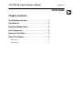
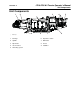
JT60/JT60 All Terrain Operator’s Manual Overview - 4 Unit Components Unit Components 1 2 j40om016w.eps 3 9 8 7 1. Carriage 6. Operator’s station 2. Spindle 7. Drill frame 3. Pipeloader 8. Tracks 4. Vise wrenches 9. Stabilizer 5.
JT60/JT60 All Terrain Operator’s Manual Overview - 5 Operator Orientation Operator Orientation 1. Front of unit 2. Right side of unit 3. Rear of unit 4. Left side of unit j40om017w.eps About This Manual This manual contains information for the proper use of this machine. See the beige Operation Overview pages for basic operating procedures. Cross references such as “See page 50” will direct you to detailed procedures.
Overview - 6 JT60/JT60 All Terrain Operator’s Manual About This Manual
JT60/JT60 All Terrain Operator’s Manual Foreword - 7 Foreword This manual is an important part of your equipment. It provides safety information and operation instructions to help you use and maintain your Ditch Witch equipment. Read this manual before using your equipment. Keep it with the equipment at all times for future reference. If you sell your equipment, be sure to give this manual to the new owner. If you need a replacement copy, contact your Ditch Witch dealer.
Foreword - 8 JT60/JT60 All Terrain Operator’s Manual JT60/All Terrain (Tier 4i) Operator’s Manual Issue number 2.0/OM-02/14 Part number 053-2547 Copyright 2013 by The Charles Machine Works, Inc. , Ditch Witch, Jet Trac, Fluid Miser, Power Pipe, and CMW are registered trademarks of The Charles Machine Works, Inc. This product is covered by one or more of the following patents: U.S.
JT60/JT60 All Terrain Operator’s Manual Safety - 11 Safety Chapter Contents Guidelines . . . . . . . . . . . . . . . . . . . . . . . . . . . . . . . . 12 Emergency Procedures . . . . . . . . . . . . . . . . . . . . . 13 • Electric Strike Description . . . . . . . . . . . . . . . . . . . . . . . . . . . . . . . . . . . 13 • If an Electric Line is Damaged . . . . . . . . . . . . . . . . . . . . . . . . . . . . . . . 14 • If a Gas Line is Damaged . . . . . . . . . . . . . . . . . . . . . . . . . . . . .
Safety - 12 JT60/JT60 All Terrain Operator’s Manual Guidelines Guidelines Follow these guidelines before operating any jobsite equipment: • Complete proper training and read operator’s manual before using equipment. • Contact your local One-Call (811 in USA) or the One-Call referral number (888-258-0808 in USA and Canada) to have underground utilities located before digging. Also contact any utilities that do not participate in the One-Call service.
JT60/JT60 All Terrain Operator’s Manual Safety - 13 Emergency Procedures Emergency Procedures Jobsite hazards could cause death or serious injury. Use correct equipment and work methods. Use and maintain proper safety equipment. Before operating any equipment, review emergency procedures and check that all safety precautions have been taken. EMERGENCY SHUTDOWN - Turn ignition switch to stop position or push remote engine stop button (if equipped). Electric Strike Description Electric shock.
Safety - 14 JT60/JT60 All Terrain Operator’s Manual Emergency Procedures If an Electric Line is Damaged If you suspect an electric line has been damaged and you are on drilling unit or bonded equipment, DO NOT MOVE. Remain on drilling machine and take the following actions. The order and degree of action will depend on the situation. • Warn people nearby that an electric strike has occurred. • Have someone contact electric company. • Reverse drilling direction and try to break contact.
JT60/JT60 All Terrain Operator’s Manual Safety - 15 Emergency Procedures If a Gas Line is Damaged Fire or explosion possible. Fumes could ignite and cause burns. No smoking, no flame, no spark. Explosion possible. Serious injury or equipment damage could occur. Follow directions carefully. If you suspect a gas line has been damaged, take the following actions. The order and degree of action will depend on the situation. • Immediately shut off engine(s), if this can be done safely and quickly.
Safety - 16 JT60/JT60 All Terrain Operator’s Manual Emergency Procedures If a Fiber Optic Cable is Damaged Do not look into cut ends of fiber optic or unidentified cable. Vision damage can occur. Contact utility company. If Machine Catches on Fire Perform emergency shutdown procedure and then take the following actions. The order and degree of action will depend on the situation. • Immediately move battery disconnect switch (if equipped and accessible) to disconnect position.
JT60/JT60 All Terrainn Operator’s Manual Safety - 17 Safety Alert Classifications Safety Alert Classifications These classifications and the icons defined on the following pages work together to alert you to situations which could be harmful to you, jobsite bystanders or your equipment. When you see these words and icons in the book or on the machine, carefully read and follow all instructions. YOUR SAFETY IS AT STAKE. Watch for the three safety alert levels: DANGER, WARNING and CAUTION.
Safety - 18 JT60/JT60 All Terrain Operator’s Manual Machine Safety Alerts Machine Safety Alerts CMW®
JT60/JT60 All Terrainn Operator’s Manual Safety - 19 Machine Safety Alerts 1 Jobsite hazards could cause death or serious injury. Use correct equipment and work methods. Use and maintain proper safety equipment. Tiedown location. See Transport chapter for more information. 7 10 24 25 Crushing weight could cause death or serious injury. Use proper procedures and equipment or stay away. Moving tools will kill or injure. Shut off drill string power when anyone can be struck by moving or thrown tools.
Safety - 20 JT60/JT60 All Terrain Operator’s Manual Machine Safety Alerts Moving parts could cut off hand or foot. Stay away. 31 Read operator’s manual. Know how to use all 34 37 controls before operating machine. When you see this sign on the machine or in the manual, read it and use caution. Your safety is at stake. Moving parts can crush. Secure extended cylinder with locking device before servicing. Lift point. See Transport chapter for more information.
JT60/JT60 All Terrain Operator’s Manual Controls - 21 Controls Chapter Contents Set-Up Controls. . . . . . . . . . . . . . . . . . . . . . . . . . . . 22 Anchor System Console . . . . . . . . . . . . . . . . . . . . 25 Left Control Console . . . . . . . . . . . . . . . . . . . . . . . 27 • Engine Display . . . . . . . . . . . . . . . . . . . . . . . . . . . . . . . . . . . . . . . . . . . 27 • ESID Strike Display. . . . . . . . . . . . . . . . . . . . . . . . . . . . . . . . . . . . . . . .
JT60/JT60 All Terrain Operator’s Manual Controls - 22 Setup Controls Setup Controls 1 2 3 4 5 6 7 8 j40om002w.eps 1. Left stabilizer control 5. Washer fluid on/off switch 2. Right stabilizer control 6. Upper wiper switch 3. Back frame tilt control 7. Lower wiper switch 4. Front frame tilt control 8. Worklight switch Item Description Notes 1. Left stabilizer control To raise, push up. IMPORTANT: Lower right and left stabilizers to the ground together, then adjust individually.
JT60/JT60 All Terrain Operator’s Manual Controls - 23 Setup Controls Item Description Notes 2. Right stabilizer control To raise, push up. IMPORTANT: Lower left and right stabilizers to the ground together, then adjust individually. To lower, pull down. 3. Back frame tilt control To raise, push up. To lower, pull down. 4. Front frame tilt control To raise, push up. To lower, pull down. 5. Washer on/off switch To start windshield washer fluid, press and hold top.
Controls - 24 JT60/JT60 All Terrain Operator’s Manual Setup Controls Item Description 6. Upper wiper switch To start wiper blade, press top. To stop wiper blade, press bottom. c00ic046w.eps 7. Lower wiper switch To start wiper blade, press top. To stop wiper blade, press bottom. c00ic047w.eps 8. Worklight switch To turn on, press top. To turn off, press bottom. c00ic048w.
JT60/JT60 All Terrain Operator’s Manual Controls - 25 Anchor System Console Anchor System Console 2 3 4 1 j40om003w.eps 1. Left rotation control 3. Right rotation control 2. Left thrust control 4. Right thrust control Item Description Notes 1. Left rotation control To remove anchor, pull. See “Anchor System” on page 119. To drive anchor, push.
Controls - 26 JT60/JT60 All Terrain Operator’s Manual Anchor System Console Item Description Notes 2. Left thrust control To move anchor up, pull. See “Anchor System” on page 119. To move anchor down, push. 3. Right rotation control To remove anchor, pull. See “Anchor System” on page 119. To drive anchor, push. 4. Right thrust control To move anchor up, pull. To move anchor down, push. See “Anchor System” on page 119.
JT60/JT60 All Terrain Operator’s Manual Controls - 27 Left Control Console Left Control Console Engine Display 4 5 6 7 8 9 3 10 2 1 12 11 j40om011w.eps 1. Voltmeter display 7. Soft key 2. Fuel level display 8. Soft key 3. Tachometer 9. Engine coolant temperature display 4. Soft key 10. Engine oil pressure display 5. Soft key 11. Hour meter 6. Main menu key 12. Drilling fluid flow display Item Description Notes 1. Voltmeter display Shows system voltage.
Controls - 28 JT60/JT60 All Terrain Operator’s Manual Left Control Console Item Description Notes 4. Soft key Press to select a soft key command. Soft key commands change with each menu screen and are displayed next to the key. 5. Soft key 6. Main menu key Press from main screen (gauges) to select main menu. 7. Soft key Press to select a soft key command. Soft key commands change with each menu screen and are displayed next to the key. 9.
JT60/JT60 All Terrain Operator’s Manual Controls - 29 Left Control Console Status Indicators ! R j40om012w.
JT60/JT60 All Terrain Operator’s Manual Controls - 30 Left Control Console ESID Strike Display 1 2 3 4 5 STRIKEDETECTED !! DO NOT EXIT THE MACHINE !! 0%V 0 %A 0 % ESID Instructions j40om013w.eps 1. Instruction display 4. Strike condition 2. Voltage indicator 5. Percentage of strike indicator 3. Current indicator The above screen is displayed when an electrical strike is detected. Follow the instructions on the screen. For more information, See “Electric Strike System” on page 123.
JT60/JT60 All Terrain Operator’s Manual Controls - 31 Left Control Console ESID Application Display 1 2 3 ACK Errors Exit ESID 0 % V 13 0 % A More 4 0 % ESID ESID_message 0 stored errors 12 11 10 9 8 7 6 5 j40om014w.eps Item Description 1. Voltage % of strike threshold 2. Amperage % of strike threshold 3. Combined % of strike threshold 4. Graphical display of electrical strike percentage 5. ESID stored error count 6. ESID error code indicator 7. ESID strobe active indicator 8.
JT60/JT60 All Terrain Operator’s Manual Controls - 32 Left Control Console Drilling Controls 5 6 8 7 9 4 3 2 10 1 11 j40om004w.eps 1. Engine throttle switch 7. Outer rotation speed control 2. Add pipe/manual/remove pipe switch 8. Spindle brake switch 3. Pipe shuttle stop switch 9. Inner spindle switch 4. Drilling fluid flow control 10. Manual inner rotation switch 5. Auto Carve Switch 11. ESID alarm interrupt / ESID self-test switch 6.
JT60/JT60 All Terrain Operator’s Manual Controls - 33 Left Control Console Item Description Notes 2. Add pipe/manual/ remove pipe switch To select “add pipe” automated pipeloader function, press right. See “Add Pipe” on page 104. To use manual pipeloader controls, move to center. c00ic058w.eps 3. Pipe shuttle stop switch To select “remove pipe” automated pipeloader function, press left. See “Remove Pipe” on page 114. To lower shuttle stop, press right.
Controls - 34 JT60/JT60 All Terrain Operator’s Manual Left Control Console Item Description Notes 6. Carve window / inner rotation speed control To increase, turn clockwise. See “Use AutoCarve” on page 108. To decrease, turn counterclockwise. c00ic053w.eps 7. Outer rotation speed control To increase outer rotation maximum speed above 75 rpm, turn clockwise. To decrease outer rotation maximum speed toward 75 rpm, turn counterclockwise.
JT60/JT60 All Terrain Operator’s Manual Controls - 35 Left Control Console Item Description Notes 10. Manual inner rotation control To rotate clockwise, move to top. IMPORTANT: • Inner spindle control must be in manual position for this control to work. • Range of speed is reduced to allow easier manual control. • Up/down paddle is spring centered. Moving it above center rotates inner rod clockwise. Moving it further rotates the rod faster.
JT60/JT60 All Terrain Operator’s Manual Controls - 36 Left Control Console Wrench Control 4 3 2 5 1 6 7 j40om005w.eps 1. Wrench control 5. Pipe lift switch 2. Wrench rotate 6. Pipe lubricator switch 3. Pipe gripper switch 7. Set/Resume switch 4. Pipe shuttle switch Item Description 1. Wrench control To clamp rear wrench, push forward. To unclamp rear wrench, pull back. To clamp front wrench, move to right. c00ic612h.eps To unclamp front wrench, move to left.
JT60/JT60 All Terrain Operator’s Manual Controls - 37 Left Control Console Item Description 2. Rear wrench rotation switch To rotate counterclockwise, press top. To rotate clockwise, press bottom. To stop rotation, release. 3. Pipe gripper switch To close, press top. To open, press bottom. 4. Pipe shuttle switch To move toward pipe box, press top. To move toward spindle, press bottom. 5. Pipe lift switch To raise, press top. To lower, press bottom. 6. Pipe lubricator switch c00ic616h.
Controls - 38 JT60/JT60 All Terrain Operator’s Manual Left Control Console Item Description Notes 7. Set/Resume switch To resume operation or increase operation levels, press top. See “Cruise Control” on page 154. To set operating conditions or reduce operation levels, press bottom. See “Use AutoCarve” on page 108.
JT60/JT60 All Terrain Operator’s Manual Controls - 39 Right Control Console Right Control Console Operation Controls 1 2 3 4 5 6 j40om006w.eps 1. Horn button 4. Cab pivot control switch 2. Ignition switch 5. Fluid flow control 3. Drill/Park/Drive switch 6. Cab pivot lock Item Description 1. Horn To sound horn, press.
Controls - 40 JT60/JT60 All Terrain Operator’s Manual Right Control Console Item Description 2. Ignition switch To start engine, insert key and turn clockwise. Notes To stop engine, turn key counterclockwise. 3. Drill/Park/Drive switch To drill, press left. IMPORTANT: To set parking brake, move to center. • Lighted icon on engine display indicates unit is ready to perform that function. • Cab must be in the correct position for drill or drive. To drive, press right. c00ic060w.eps 4.
JT60/JT60 All Terrain Operator’s Manual Controls - 41 Right Control Console Gauges and Indicators 4 3 5 2 1 7 6 j40om007w.eps 1. Diagnostic indicator (red) 5. Drilling fluid pressure gauge 2. Control cycle indicator (green) 6. Drilling fluid pump indicator (red) 3. Thrust pressure gauge 7. Drilling fluid pump status indicator (red) 4.
JT60/JT60 All Terrain Operator’s Manual Controls - 42 Right Control Console Item Description 1. Diagnostic indicator (red) If system is OK, light should be off. ! Notes If system may not be getting power, light should be on. If a non-essential diagnostic code is recorded, light should flash on and off for 10 seconds. See “Wireline Tracking” on page 156. c00ic062w.eps If an essential diagnostic code is recorded, light should flash on for three seconds and off for half a second. 2.
JT60/JT60 All Terrain Operator’s Manual Controls - 43 Right Control Console Item Description Notes 5. Rotation pressure gauge Displays hydraulic fluid pressure to rotation motor when spindle is turned clockwise. Inner rotation pressure is displayed when inner rotation is on and front wrench is open. Outer rotation pressure is displayed when front wrench is closed and during backreaming. 6. Drilling fluid pressure gauge Displays drilling fluid pressure in the drilling fluid hard line. 7.
JT60/JT60 All Terrain Operator’s Manual Controls - 44 Right Control Console Drill/Drive Control 3 4 2 1 j40om008w.eps 1. Drilling fluid pump switch 3. Drilling fluid quick fill switch 2. Dual speed carriage/Two-speed ground drive control 4. Track and carriage control Item Description 1. Drilling fluid pump switch To turn on, press once. To turn off, press once.
JT60/JT60 All Terrain Operator’s Manual Controls - 45 Right Control Console Item Description Notes 2. Dual speed carriage/ Two-speed ground drive control Carriage travel speed: Use during bore or pullback when no pipe is in spindle to save time. • • 3. Drilling fluid quick fill switch To increase, push and hold. To return to normal carriage speed, release. IMPORTANT: Drill/Park/Drive switch must be in drill position. Ground drive speed: Use when driving straight.
JT60/JT60 All Terrain Operator’s Manual Controls - 46 Seat Seat 4 j40om067w.eps 1. Seat recline control 3. Seat lumbar control 2. Seat slide control 4. Seat belt Item Description 1. Seat recline control To raise seatback, turn toward anchors. To recline seatback, turn toward engine compartment. 2. Seat slide control To slide forward or backward, move left. To lock seat in position, release. 3. Seat lumbar control For least support, move up. For medium support, move down.
JT60/JT60 All Terrain Operator’s Manual Controls - 47 Cab Controls Cab Controls EMERGENCY EXIT: Push rear window out to exit cab when door is blocked or inoperable. Top/Rear 1 3 2 4 5 j29om002t.eps 1. Dome light switch 4. Air conditioner fan speed dial 2. Air conditioner on/off switch 5. Air conditioner filter 3. Air conditioner temperature dial Item Description 1. Dome light switch To turn on or off, press. 2. AC on/off switch To turn air conditioner on, press left.
Controls - 48 JT60/JT60 All Terrain Operator’s Manual Cab Controls Item Description 3. AC temperature dial To adjust air temperature, turn dial. 4. AC fan speed dial To adjust fan speed, turn dial. 5. Air conditioner filter Filters air coming into cab. Notes Clean or replace air filter as needed.
JT60/JT60 All Terrain Operator’s Manual Controls - 49 Override Box Override Box 1 2 A 3 B 4 j40om073w.eps 1. Tracker control key 4. Thrust/pullback or left track override switch 2. Drilling fluid flow override switch 5. Drill override port 3. Rotation or right track override switch 6. Drive override port Item Description Notes 1. Tracker control key To allow tracker operator to stop thrust and rotation, move key to enable position (up).
Controls - 50 JT60/JT60 All Terrain Operator’s Manual Override Box Item Description Notes 3. Thrust/pullback or left track override switch For thrust or to move track forward, move up. Connect to drill connector (B) to control thrust/pullback. For pullback or to move track backward, move down. Connect to drive connector (A) to control left track. IMPORTANT: When connected to connector (A), drill fluid switch functions as an operator presence switch. 4.
JT60/JT60 All Terrain Operator’s Manual Controls - 51 Battery Battery 1 j40om019w.eps Item Description Notes 1. Battery disconnect switch To disconnect, turn switch counterclockwise. IMPORTANT: Use when servicing unit and during long-term storage. To connect, turn switch clockwise.
JT60/JT60 All Terrain Operator’s Manual Controls - 52 Engine Compartment Engine Compartment 3 2 1 4 j40om009w.eps 1. Manual throttle switch 3. Fan speed switch 2. Drill mode switch (optional) 4. Inner rotation hour meter (optional) Item Description Notes 1. Manual throttle switch To throttle up, press top of switch. IMPORTANT: Switch only functions if CAN communication is not operable. To throttle down, press bottom of switch.
JT60/JT60 All Terrain Operator’s Manual Controls - 53 Engine Compartment Item Description Notes 2. Drill mode switch To select AT Rock mode, press top. Use AT Rock mode when using AT pipe with inner rod and rock drilling bits. To select AT Dirt mode, move to middle. To select JT mode, press bottom. Use AT Dirt mode when using AT pipe with inner rod and adapter to use dirt tool head. Use JT drilling mode when using JT pipe without inner rod.
JT60/JT60 All Terrain Operator’s Manual Controls - 54 Rear Console Rear Console 1 j40om010w.eps 1. Pressure wand on/off switch Item Description 1. Pressure wand on/off switch To turn pressure wand on, press top. To turn pressure wand off, press bottom. c00ic064w.
JT60/JT60 All Terrain Operator’s Manual Operation Overview - 55 Operation Overview Chapter Contents Planning. . . . . . . . . . . . . . . . . . . . . . . . . . . . . . . . . . 56 Setting Up at Jobsite . . . . . . . . . . . . . . . . . . . . . . . 56 Drilling . . . . . . . . . . . . . . . . . . . . . . . . . . . . . . . . . . . 57 Backreaming . . . . . . . . . . . . . . . . . . . . . . . . . . . . . . 58 Leaving Jobsite. . . . . . . . . . . . . . . . . . . . . . . . . . . . 58 Storing Equipment . . . . . .
Operation Overview - 56 JT60/JT60 All Terrain Operator’s Manual Planning Planning 1. Gather information about jobsite. See page 61. 2. Inspect jobsite. See page 62. 3. Classify jobsite. See page 64. 4. Plan bore path. See page 67. 5. Select drilling mode based on jobsite conditions. See page 79. 6. Check supplies and prepare equipment. See page 77. 7. Load equipment. See page 89. Setting Up at Jobsite 1. Prepare jobsite. See page 76. 2. Unload drilling unit from trailer. See page 91. 3.
JT60/JT60 All Terrain Operator’s Manual Operation Overview - 57 Drilling Drilling 1. Start system. See page 95. 2. Engage tracker control if desired. See page 133. 3. Drill first pipe. See page 102. • JT mode • AT dirt mode • AT mode 4. Swab the hole to remove cuttings (AT mode only). See page 103. 5. Record bore path. See page 110. 6. Add pipe. See page 104. 7. Drill remaining pipes in pipe box. • Correct direction. See page 106. • Engage cruise control. See page 154. 8.
Operation Overview - 58 JT60/JT60 All Terrain Operator’s Manual Backreaming Backreaming 1. Assemble backream string. See page 99. 2. Start drilling unit and adjust throttle. 3. Set drilling fluid flow. Check that fluid flows through all nozzles. See page 136. 4. Remove pipe from bore. See page 114. 5. Remove full pipe box and add empty box (see page 147) or remove up to a single row of drill pipe from full box (see page 149) to complete backream. 6. Remove pullback device. See page 116.
JT60/JT60 All Terrain Operator’s Manual Prepare - 59 Prepare Chapter Contents Gather Information . . . . . . . . . . . . . . . . . . . . . . . . . 61 • Review Job Plan . . . . . . . . . . . . . . . . . . . . . . . . . . . . . . . . . . . . . . . . . . 61 • Notify One-Call Services . . . . . . . . . . . . . . . . . . . . . . . . . . . . . . . . . . . . 61 • Examine Pullback Material . . . . . . . . . . . . . . . . . . . . . . . . . . . . . . . . . . 61 • Arrange for Traffic Control. . . . . . . . .
Prepare - 60 JT60/JT60 All Terrain Operator’s Manual Prepare Jobsite . . . . . . . . . . . . . . . . . . . . . . . . . . . . 76 • Mark Bore Path . . . . . . . . . . . . . . . . . . . . . . . . . . . . . . . . . . . . . . . . . . . 76 • Prepare Entry Point. . . . . . . . . . . . . . . . . . . . . . . . . . . . . . . . . . . . . . . . 76 Check Supplies and Prepare Equipment . . . . . . . 77 • Check Supplies . . . . . . . . . . . . . . . . . . . . . . . . . . . . . . . . . . . . . . . . . . .
JT60/JT60 All Terrain Operator’s Manual Prepare - 61 Gather Information Gather Information A successful job begins before the bore. The first step in planning is reviewing information already available about the job and jobsite. Review Job Plan Review blueprints or other plans and make sure you have taken bore enlargement during backreaming and pullback into account. Check for information about existing or planned structures, elevations, or proposed work that may be taking place at the same time.
JT60/JT60 All Terrain Operator’s Manual Prepare - 62 Inspect Site Inspect Site Inspect jobsite before transporting equipment. Check for the following: • overall grade or slope • changes in elevation such as hills or open trenches • obstacles such as buildings, railroad crossings, or streams • signs of utilities (See “Inspect Jobsite” on page 64.) • traffic • access • soil type and condition • water supply • sources of locator interference (rebar, railroad tracks, etc.
JT60/JT60 All Terrain Operator’s Manual Prepare - 63 Inspect Site Select Start and End Points Select one end to use as a starting point. Consider the following when selecting a starting point: Slope Always level machine before drilling. Fluid system should be parked on a level site. Consider how slope will affect drilling unit setup, bending pipe, and fluid flow out of hole. Traffic Vehicle and pedestrian traffic must be a safe distance from drilling equipment.
Prepare - 64 JT60/JT60 All Terrain Operator’s Manual Classify Jobsite Classify Jobsite Inspect Jobsite • Follow U.S. Department of Labor regulations on excavating and trenching (Part 1926, Subpart P) and other similar regulations. • Contact your local One-Call (811 in USA) or the One-Call referral number (888-258-0808 in USA and Canada) to have underground utilities located before digging. Also contact any utilities that do not participate in the One-Call service.
JT60/JT60 All Terrain Operator’s Manual Prepare - 65 Classify Jobsite Apply Precautions Once classified, precautions appropriate for jobsite must be taken. Electric Jobsite Precautions Electric shock. Contacting electric lines will cause death or serious injury. Know location of lines and stay away. In addition to using a directional drilling system with an electric strike system, use one or both of these methods. • Expose line by careful hand digging or soft excavation.
JT60/JT60 All Terrain Operator’s Manual Prepare - 66 Classify Jobsite Crystalline Silica (Quartz) Dust Precautions Jobsite hazards could cause death or serious injury. Use correct equipment and work methods. Use and maintain proper safety equipment. To help avoid injury: • Use water spray or other means to control dust when cutting, drilling, or working materials such as concrete, sand, or rock containing quartz. The dust may contain silica.
JT60/JT60 All Terrain Operator’s Manual Prepare - 67 Plan Bore Path Plan Bore Path Plan the bore path, from entry to end, before drilling begins. The Ditch Witch Trac Management System Plus is available for planning your bore path. See your Ditch Witch dealer for details. If not using Trac Management System Plus, mark the bore path on the ground with spray paint or flags, or record it on paper for operator reference. For complicated bores, consult an engineer.
Prepare - 68 JT60/JT60 All Terrain Operator’s Manual Plan Bore Path Recommended Bend Limits NOTICE: Only use approved JT60 Power Pipe HD, All Terrain Power Pipe, or Power Pipe Forged with this drilling unit. Ditch Witch drill pipes are designed to bend slightly during operation. Slight bending allows for steering and correcting direction. Bending beyond recommended limits will cause damage that might not be visible. This damage adds up and will later lead to sudden drill pipe failure.
JT60/JT60 All Terrain Operator’s Manual Prepare - 69 Plan Bore Path JT60 Power Pipe drill pipes have a tested minimum bend radius of 170’ (57.8 m). This means that a 90degree bend in the bore path: • has a radius (A) of 170’ (57.8 m) • requires approximately 267’ (81.4 m) of drill pipe (B). JT60 Power Pipe Forged drill pipes have a tested minimum bend radius of 168.7’ (51.4 m). This means that a 90-degree bend in the bore path: • has a radius (A) of 168.7’ (51.
JT60/JT60 All Terrain Operator’s Manual Prepare - 70 Plan Bore Path Pipe-By-Pipe Bend Limits - JT60 Power Pipe HD Pipe (C) Deflection (A) Forward (B) Pipe (C) Deflection (A) Forward (B) 1 0’ 7.9” 14’ 11.8” 10 61’ 11.9” 131’ 3.4” 2 2’ 7.7” 29’ 10.1” 11 73’ 11.8” 140’ 3.4’ 3 5’ 11.1” 44’ 5.7” 12 86’ 8.6” 148’ 2.4” 4 10’ 5.7” 58’ 9.1” 13 100’ 1.2” 154’ 11.6” 5 16’ 3.3” 72’ 7.1” 14 114’ 0.3” 160’ 6.3” 6 23’ 3.3” 85’ 10.3” 15 128’ 4.7” 164’ 10.0” 7 31’ 4.9” 98’ 5.
JT60/JT60 All Terrain Operator’s Manual Prepare - 71 Plan Bore Path Pipe-By-Pipe Bend Limits - JT60 Power Pipe All Terrain Pipe (C) Deflection (A) Forward (B) Pipe (C) Deflection (A) Forward (B) 1 0’ 5.9” 14’ 3.0” 13 78’ 3.1” 161’ 1.5” 2 1’ 11.8” 28’ 5.1” 14 89’ 9.2” 169’ 6.6” 3 4’ 5.4” 42’ 5.6” 15 101’ 9.9” 177’ 1.8” 4 7’ 10.6” 56’ 3.7” 16 114’ 4.7” 183’ 10.7” 5 12’ 3.3” 69’ 10.5” 17 127’ 4.7” 189’ 8.9” 6 17’ 7.2” 83’ 1.2” 18 140’ 9.2” 194’ 8.1” 7 23’ 9.
Prepare - 72 JT60/JT60 All Terrain Operator’s Manual Plan Bore Path Entry Pitch Entry pitch is the slope of the drill frame compared with the slope of the ground. Determine entry pitch one of two ways: 1. With Pitch Beacon • Lay pitch beacon on the ground and read pitch. • Lay pitch beacon on drill frame and read pitch. • Subtract ground pitch from drilling unit pitch. 2. With Measurements • Measure from the ground to front end of drill frame (H1).
JT60/JT60 All Terrain Operator’s Manual Prepare - 73 Plan Bore Path Minimum Depth Because you must bend pipe gradually, entry pitch and bend limits determine how deep the pipe will be when it becomes horizontal. This is called the minimum depth. • To reduce minimum depth (D1), reduce entry pitch. This also decreases setback. • To increase minimum depth (D2), increase entry pitch. This also increases setback.
JT60/JT60 All Terrain Operator’s Manual Prepare - 74 Plan Bore Path JT60 Power Pipe Forged Minimum depth (D) Entry pitch (A) Setback (B) Depth to begin steering (S) 4’ 10” 18”/10.0° 41’ 12” 2’ 3” 5’ 7” 19%/11.0° 44’ 10” 2’ 6” 6’ 5” 21%/12.0° 47’ 9” 2’ 8” 7’ 3” 23%/13.0° 50’ 6” 2’ 11” 8’ 2” 25%/14.0° 53’ 4” 3’ 2” 9’ 1” 27%/15.0° 56’ 2” 3’ 4” 10’ 1” 29%/16.0° 58’ 11” 3’ 7” IMPORTANT: Numbers in table based on 168.7’ (51.
JT60/JT60 All Terrain Operator’s Manual Prepare - 75 Plan Bore Path JT60 Power Pipe AT Minimum depth (D) Entry pitch (A) Setback (B) Depth to begin steering (S) 5’ 4” 18”/10.0° 47’ 12” 2’ 3” 6’ 2” 19%/11.0° 51’ 6” 2’ 5” 7’ 2” 21%/12.0° 54’ 11” 2’ 8” 8’1” 23%/13.0° 58’ 5” 2’ 10” 9’ 2” 25%/14.0° 61’ 10” 3’ 1” 10’ 3” 27%/15.0° 65’ 3” 3’ 4” 11’ 5” 29%/16.0° 68’ 7” 3’ 6” IMPORTANT: Numbers in table based on 168.7’ (51.
JT60/JT60 All Terrain Operator’s Manual Prepare - 76 Prepare Jobsite Prepare Jobsite Jobsite hazards could cause death or serious injury. Use correct equipment and work methods. Use and maintain proper safety equipment. To help prevent injury: • Classify jobsite as electric if jobsite classification is in question or if the possibility of unmarked electric utilities exists. • Cutting high voltage cable can cause electrocution. Expose lines by hand before digging.
JT60/JT60 All Terrain Operator’s Manual Prepare - 77 Check Supplies and Prepare Equipment Check Supplies and Prepare Equipment Check Supplies • receiver/transmitter or tracker with spare batteries • beacons with new and spare batteries • two-way radios with new and spare batteries • hydraulic wrench (see “Hydratong Wrenches” on page 141) • transition sub • anchoring equipment and accessories • bits, screens, nozzles (see “Downhole Tools” on page 136) • adapters, pipe, beacon housings • m
Prepare - 78 JT60/JT60 All Terrain Operator’s Manual Check Supplies and Prepare Equipment Prepare Equipment Fluid Levels • fuel • hydraulic fluid • engine coolant • battery charge • engine oil Condition and Function • filters (air, oil, hydraulic) • fluid pump • couplers • tires and tracks • pumps and motors • drilling fluid mixer • hoses and valves • water tanks
JT60/JT60 All Terrain Operator’s Manual Prepare - 79 Check Supplies and Prepare Equipment Select Drilling Mode Three drilling setups are available with this unit: • AT rock mode • AT dirt mode • JT mode Select the best setup based on jobsite conditions. Mode Situation used Downhole tools Capabilities AT Rock Rock, soft rock, other non-compressible soils. Any other situation with difficult steering because of hard soil conditions.
Prepare - 80 JT60/JT60 All Terrain Operator’s Manual Check Supplies and Prepare Equipment Prepare Drilling Unit AT Rock Mode • Verify unit has not been converted to JT mode. Ensure All Terrain SaverLok, shuttle stops, pipe gripper pads, pipe guide blocks, pipe wiper, shuttle stop, wrench jaw blocks, and pipe lifter pads are installed. • Inspect Rockmaster tool and select bit based on jobsite conditions. • Use drill bit type anchors. • Load All Terrain pipe and pipe box onto unit.
JT60/JT60 All Terrain Operator’s Manual Prepare - 81 Check Supplies and Prepare Equipment JT Mode IMPORTANT: Use conversion kit (p/n 101-136) and refer to installation instructions (p/n 051-329). • Install SaverLok, pipe gripper pads, pipe guide blocks, pipe wiper, shuttle stop, wrench jaw blocks, and pipe lifter pads sized to handle Mach 1 pipe. • Use standard transition sub and beacon housing. Select soil bit based on jobsite conditions. • Use auger type anchors.
Prepare - 82 JT60/JT60 All Terrain Operator’s Manual Check Supplies and Prepare Equipment
JT60/JT60 All Terrain Operator’s Manual Drive - 83 Drive Chapter Contents Start Unit . . . . . . . . . . . . . . . . . . . . . . . . . . . . . . . . . 84 Steer Unit . . . . . . . . . . . . . . . . . . . . . . . . . . . . . . . . 84 Shut Down Unit . . . . . . . . . . . . . . . . . . . . . . . . . . .
Drive - 84 JT60/JT60 All Terrain Operator’s Manual Start Unit Start Unit 1. Insert key. 2. Turn ignition switch to the run position (key on, engine off). Engine preheat indicator (on engine display) will light. 3. Wait for engine preheat indicator to go off before starting. 4. Run engine at low throttle for 5 minutes. Steer Unit IMPORTANT: Survey field of vision before operating the machine and position all mirrors provided to ensure that visibility is not restricted.
JT60/JT60 All Terrain Operator’s Manual Drive - 85 Steer Unit Safe Slope Operation Tipover possible. Machine can tip over and crush you. To help avoid injury: • Always operate with heavy end uphill. • Drive cautiously at all times. • Never jerk control levers. Use a steady even motion. • Do not park unit on slope without lowering anchor frame to the ground, returning all controls to neutral position, shutting down unit, and applying parking brake.
Drive - 86 JT60/JT60 All Terrain Operator’s Manual Shut Down Unit Shut Down Unit 1. Stop track movement. 2. Engage parking brake. 3. Run engine at low throttle for 3 minutes to cool. 4. Turn ignition switch to STOP. 5. Remove key.
JT60/JT60 All Terrain Operator’s Manual Transport - 87 Transport Chapter Contents Lift . . . . . . . . . . . . . . . . . . . . . . . . . . . . . . . . . . . . . . 88 Haul . . . . . . . . . . . . . . . . . . . . . . . . . . . . . . . . . . . . . 89 • Load . . . . . . . . . . . . . . . . . . . . . . . . . . . . . . . . . . . . . . . . . . . . . . . . . . . 89 • Tie Down . . . . . . . . . . . . . . . . . . . . . . . . . . . . . . . . . . . . . . . . . . . . . . . 90 • Unload . . . . . . . . . . . . . .
JT60/JT60 All Terrain Operator’s Manual Transport - 88 Lift Lift This machine is not configured for lifting. If the machine must be lifted, load machine into a container or onto a platform appropriate for lifting. See “Specifications” for weight of machine. Pipe Box Lifting Procedure Crushing weight could cause death or serious injury. Use proper procedures and equipment or stay away. Pipe box lifting points are identified by lifting decals. Lifting at other points is unsafe and can damage equipment.
JT60/JT60 All Terrain Operator’s Manual Transport - 89 Haul Haul Load Crushing weight. If load falls or moves it could kill or crush you. Use proper procedures and equipment or stay away. To help avoid injury: • Load and unload trailer on level ground. • Verify that trailer wheels are blocked. • Attach trailer to vehicle before loading or unloading. • Place ten to fifteen percent of total vehicle weight (equipment plus trailer) on tongue to help prevent trailer sway. 1.
JT60/JT60 All Terrain Operator’s Manual Transport - 90 Haul Tie Down Points Tiedown points are identified by tiedown decals. Securing to trailer at other points is unsafe and can damage machinery. Procedure NOTICE: • Wrenches can open after engine shutdown. Ensure that any pipe in wrenches is attached to spindle and downhole tools are removed from the pipe before transport. • Use Grade 7-3/8” (18.7 cm) transport chain to secure drilling unit. Loop a transport chain around each tie down point.
JT60/JT60 All Terrain Operator’s Manual Transport - 91 Tow Unload Crushing weight. If load falls or moves it could kill or crush you. Use proper procedures and equipment or stay away. To help avoid injury: • Load and unload trailer on level ground. • Ensure trailer wheels are blocked. • Attach trailer to vehicle before loading or unloading. 1. Lower trailer or ramps. 2. Fasten and adjust seat belt. 3. Remove tiedowns. 4. Start drilling unit engine. 5. Raise stabilizers. 6. Raise drill frame. 7.
JT60/JT60 All Terrain Operator’s Manual Transport - 92 Tow To disengage track planetaries, reverse small cover plate in center of planetary on each track drive. IMPORTANT: When planetaries are disengaged, unit has no brakes. A. Normal operation B. Towing To attach chains to tow points, determine which points are facing towing vehicle. If back tow points are facing towing vehicle, choose option A or B. Option A: Loop chain through both tow points and attach to common cross member.
JT60/JT60 All Terrain Operator’s Manual Conduct a Bore - 93 Conduct a Bore Chapter Contents Position Equipment . . . . . . . . . . . . . . . . . . . . . . . . 95 Connect Fluid System . . . . . . . . . . . . . . . . . . . . . . 95 Start System . . . . . . . . . . . . . . . . . . . . . . . . . . . . . . 95 Prime Drilling Fluid Pump . . . . . . . . . . . . . . . . . . . 96 Operate Carriage Control . . . . . . . . . . . . . . . . . . . 97 Clamp Pipe . . . . . . . . . . . . . . . . . . . . . . . . . . . . . .
Conduct a Bore - 94 JT60/JT60 All Terrain Operator’s Manual Add Pipe . . . . . . . . . . . . . . . . . . . . . . . . . . . . . . . . 104 Correct Direction . . . . . . . . . . . . . . . . . . . . . . . . . 106 • Basic Rules . . . . . . . . . . . . . . . . . . . . . . . . . . . . . . . . . . . . . . . . . . . . 106 • Procedure . . . . . . . . . . . . . . . . . . . . . . . . . . . . . . . . . . . . . . . . . . . . . . 107 • Drill Head Position . . . . . . . . . . . . . . . . . . . . . . . . . . . . . .
JT60/JT60 All Terrain Operator’s Manual Conduct a Bore - 95 Position Equipment Position Equipment 1. Review bore plan and select drilling unit position and fluid unit position. 2. Move equipment into selected positions. Connect Fluid System Electric shock. Contacting electric lines will cause death or serious injury. Know location of lines and stay away. To help avoid injury, do not connect drilling unit to a public or private (business or home) water supply.
Conduct a Bore - 96 JT60/JT60 All Terrain Operator’s Manual Prime Drilling Fluid Pump Prime Drilling Fluid Pump Incorrect procedures could result in death, injury, or property damage. Learn to use equipment correctly. To help avoid injury, prime the drilling fluid pump before use. Failure to prime the drilling fluid pump will cause flow fluctuations, which will make it difficult to control the wash wand. Pressurized fluid or air could pierce skin and cause injury or death. Stay away.
JT60/JT60 All Terrain Operator’s Manual Operate Carriage Control Operate Carriage Control The thrust/rotation control has eight zones that allow four basic functions (forward, backward, clockwise, counterclockwise) to be combined. The chart below summarizes functions that occur when control is put at a combined position. Operator must be in seat for control to function.
Conduct a Bore - 98 JT60/JT60 All Terrain Operator’s Manual Clamp Pipe Clamp Pipe Turning shaft can kill you or crush arm or leg. Stay away. To help avoid injury, clamp pipe only where shown. Clamping anywhere else on the pipe will weaken the pipe. Pipe can later break, even when operating under normal loads. Clamp on pipe when joint is centered between wrenches (1 and 2). Always clamp on the larger diameter areas on either side of the tool joint face. j40om066w.
JT60/JT60 All Terrain Operator’s Manual Conduct a Bore - 99 Assemble Drill String Assemble Drill String 1 1 2 1 2 2 3 4 4 3 3 j07om046c.eps JT mode AT Dirt mode AT Rock mode 1. beacon housing 1. beacon housing 1. Rockmaster tool 2. bit 2. bit 2. bit 3. transition sub 3. transition sub 3. JT60 All Terrain drill pipe 4. JT60 drill pipe 4. JT60 All Terrain drill pipe IMPORTANT: If no part number is listed, contact your Ditch Witch dealer about available options.
Conduct a Bore - 100 JT60/JT60 All Terrain Operator’s Manual Assemble Drill String Attach Transition Sub Use either machine torque or Hydratong wrenches to attach transition sub. Machine Torque 1. Pull transition sub into front wrench. 2. Close wrench. 3. Lube joints. 4. Slowly make up joint. 5. Use full machine torque to tighten joint fully. Hydratong 1. Lube joints with TJC. 2. Attach Hydratong to the joint in the join position and tighten joint. See “Hydratong Wrenches” on page 141.
JT60/JT60 All Terrain Operator’s Manual Conduct a Bore - 101 Assemble Drill String Connect Drill Pipe 1. Start drilling unit engine. 2. Align transition sub in front wrench. 3. Clamp tool in front wrench. See “Clamp Pipe” on page 98. 4. Load pipe. • Make sure shuttle stop is positioned correctly. • Lubricate threads in front wrench. • Grip pipe. • Move pipe to spindle. 5. Connect pipe. • Move carriage forward until SaverLok nears male pipe thread.
JT60/JT60 All Terrain Operator’s Manual Conduct a Bore - 102 Drill First Pipe Drill First Pipe Turning shaft can kill you or crush arm or leg. Stay away. To help avoid injury: • Keep everyone at least 10’ (3 m) away from turning drill string. • Push rod or pipe slowly. Forcing can bend string. Do not use bent rod or pipe. Jobsite hazards could cause death or serious injury. Use correct equipment and work methods. Use and maintain proper safety equipment. JT Mode/AT Dirt Mode 1.
JT60/JT60 All Terrain Operator’s Manual Conduct a Bore - 103 Swab the Hole Swab the Hole IMPORTANT: Swab hole after each pipe is drilled to remove cuttings and keep the hole clear (AT Rock mode only). Some conditions may require more frequent swabbing. 1. Move carriage forward until wrench springs are fully compressed. 2. Move carriage to rear of drill frame with drilling fluid and inner rotation on. 3.
Conduct a Bore - 104 JT60/JT60 All Terrain Operator’s Manual Add Pipe Add Pipe 1. Press drilling unit throttle switch until engine is at full throttle. 2. Enable automated pipeloader system (automated pipeloader control only). See “Enable Automated Pipeloader System” on page 103. 3. Break joint at SaverLok. Manual Pipeloader Controls Automated Pipeloader Control • Clamp pipe joint. See “Clamp Pipe” on page 98. • Clamp pipe joint. See “Clamp Pipe” on page 98. • Locate drill head.
JT60/JT60 All Terrain Operator’s Manual Conduct a Bore - 105 Add Pipe 5. Connect pipe to SaverLok. Manual Pipeloader Controls Automated Pipeloader Control IMPORTANT: Always rotate clockwise unless breaking pipe joint. Rotating counterclockwise will separate joints. IMPORTANT: Always rotate clockwise unless breaking pipe joint. Rotating counterclockwise will separate joints. • Move carriage forward until SaverLok meets pipe. • Move carriage forward until SaverLok meets pipe.
Conduct a Bore - 106 JT60/JT60 All Terrain Operator’s Manual Correct Direction Correct Direction Correcting direction is a skill operators gain with experience and knowledge of equipment and soil conditions. These instructions cover only basic procedures. For information about specific equipment or jobsites, contact your Ditch Witch dealer. To track progress and make corrections, one crew member locates the drill head and sends instructions to the operator.
JT60/JT60 All Terrain Operator’s Manual Conduct a Bore - 107 Correct Direction Procedure 1. Locate drill head. Take readings available with your beacon and locating equipment such as: • depth • pitch • left/right information • temperature • beacon roll 2. Compare position to bore plan. Determine direction drilling should go. 3. Position drill head. 4. Drill in pipe. Drill Head Position The drill head position is determined by reading beacon roll. Roll is displayed as a clock face position. 1.
JT60/JT60 All Terrain Operator’s Manual Conduct a Bore - 108 Use AutoCarve Use AutoCarve AutoCarve helps the operator change direction when thrust stalls in difficult soil conditions. AutoCarve rotates the bit clockwise and counterclockwise to grind away soil, clearing a path to improve steering through tough formations. Movement Description alternating clockwise and counterclockwise rotation Enables the downhole tool to carve tough soil formations. Rotation speed can be adjusted during autocarving.
JT60/JT60 All Terrain Operator’s Manual Conduct a Bore - 109 Use AutoCarve Operation IMPORTANT: • 2-speed thrust is not allowed in AutoCarve mode. • AutoCarve mode is disabled while front wrench is closed. • Adding or removing pipe does not affect AutoCarve position. 1. Position downhole tool for carving. Rotate the toolhead to the desired position. 2. Turn on AutoCarve mode. Press top of AutoCarve switch. 3. Begin carving.
JT60/JT60 All Terrain Operator’s Manual Conduct a Bore - 110 Record Bore Path Record Bore Path Locate drill head every half-length of pipe. As the job is completed, record the actual data for each drill pipe. List pitch and depth of each joint and a brief description of the procedure. In addition, draw a simple sketch of the site and record depth and rough location of pullback. The Trac Management System Plus is also available for plotting and tracking your bore path.
JT60/JT60 All Terrain Operator’s Manual Conduct a Bore - 111 Surface Drill Head 1. Guide drill head to target pit or up through surface. Make all bends gradual. See “Recommended Bend Limits” on page 68. 2. Clean area around exit point. 3. If using tracker control mode, tracker operator turns off tracker to disable drilling unit thrust/pullback and rotation hydraulics. Tracker operator waits for green light to enter pit and change tools.
Conduct a Bore - 112 JT60/JT60 All Terrain Operator’s Manual Backream Backream Sometimes it is necessary to enlarge the pilot hole to accommodate larger product. As a general rule, the final hole should be 1.5 times larger than the diameter of the product being installed. The number of passes needed depends on soil conditions. Do not try to increase hole size too much in one pass. Several passes using successively larger reamers will save wear on machine. Moving tools will kill or injure.
JT60/JT60 All Terrain Operator’s Manual Conduct a Bore - 113 Backream 1 3 1 1 2 3 2 3 2 j07om074h.eps JT mode AT Dirt mode AT Rock mode 1. backreamer 1. backreamer 1. backreamer 2. transition sub 2. transition sub 2. transition sub 3. JT60 drill pipe 3. JT60 All Terrain drill pipe 3. JT60 All Terrain drill pipe IMPORTANT: If no part number is listed, contact your Ditch Witch dealer about available options. 1. Select backreaming devices. See “Backreamers” on page 138. 2.
Conduct a Bore - 114 JT60/JT60 All Terrain Operator’s Manual Remove Pipe Remove Pipe 1. Enable automated pipeloader system (automated pipeloader control only). See “Enable Automated Pipeloader System” on page 103. 2. Clamp pipes. See “Clamp Pipe” on page 98. 3. Break front joint: • Turn rear wrench counterclockwise to break joint. • Disengage rear wrench and rotate wrench clockwise. 4. Grip pipe: Manual Pipeloader Controls Automated Pipeloader Control • Open grippers. • • Lift pipe off shuttles.
JT60/JT60 All Terrain Operator’s Manual Conduct a Bore - 115 Remove Pipe 6. Break rear joint: Manual Pipeloader Controls Automated Pipeloader Control • Engage rear wrench. • Engage rear wrench. • Slowly rotate spindle counterclockwise and move carriage back until joint is loosened. Do not fully separate joint. • Slowly rotate spindle counterclockwise and move carriage back until joint is loosened. Do not fully separate joint. • Disengage rear wrench. • Disengage rear wrench.
Conduct a Bore - 116 JT60/JT60 All Terrain Operator’s Manual Remove Pullback Device Remove Pullback Device The pullback device can be removed when the last pipe is on the frame. It can also be removed when a target pit along the bore path has been reached. Remaining pipe is then pulled back and removed. Moving tools will kill or injure. Shut off drill string power when anyone can be struck by moving or thrown tools. Never use pipe wrenches on drill string. 1.
JT60/JT60 All Terrain Operator’s Manual Systems and Equipment - 117 Systems and Equipment Chapter Contents Anchor System . . . . . . . . . . . . . . . . . . . . . . . . . . . 119 • Anchors . . . . . . . . . . . . . . . . . . . . . . . . . . . . . . . . . . . . . . . . . . . . . . . 120 • Alternate Anchoring . . . . . . . . . . . . . . . . . . . . . . . . . . . . . . . . . . . . . . 122 Electric Strike System . . . . . . . . . . . . . . . . . . . . . 123 • FCC Statement . . . . . . . . . . . . . . . .
Systems and Equipment - 118 JT60/JT60 All Terrain Operator’s Manual Downhole Tools . . . . . . . . . . . . . . . . . . . . . . . . . . 136 • Nozzles . . . . . . . . . . . . . . . . . . . . . . . . . . . . . . . . . . . . . . . . . . . . . . . 136 • Bits . . . . . . . . . . . . . . . . . . . . . . . . . . . . . . . . . . . . . . . . . . . . . . . . . . . 136 • Beacon Housings . . . . . . . . . . . . . . . . . . . . . . . . . . . . . . . . . . . . . . . . 137 • Backreamers . . . . . . . . . . . . . .
JT60/JT60 All Terrain Operator’s Manual Systems and Equipment - 119 Anchor System Anchor System Three methods for anchoring this unit are available: anchors, remote tie-offs, and a combination of both. Choose the correct method based on jobsite conditions. Crushing weight. If load falls or moves, it could kill or crush you. Use proper procedures and equipment or stay away. To help avoid injury: • Set stabilizers prior to driving anchors. • Drive anchors properly and/or tie off unit before drilling.
Systems and Equipment - 120 JT60/JT60 All Terrain Operator’s Manual Anchor System Anchors Select Anchor Two anchor types are available. Choose the correct anchor type based on jobsite conditions. Anchor type Situation used rock bit hard/soft rock, asphalt, concrete, cobble auger bit soft soil to hard soil, soft rock IMPORTANT: Do not attempt to operate anchor controls while drill fluid is on. Drill fluid operation may divert power from anchor system so that anchor controls perform poorly.
JT60/JT60 All Terrain Operator’s Manual Systems and Equipment - 121 Anchor System Drive Anchors (Soil) IMPORTANT: Carefully time anchor rotation with anchor movement. Properly driven anchors should not auger up soil. 1. Raise anchor shaft to top of anchor frame. 2. Use rotation and thrust controls to drive anchor into ground. NOTICE: • Rotate augers slowly and thrust hard to thread auger into the ground. • Centering cap MUST be positioned in centering tube to prevent damage to anchor. 3.
Systems and Equipment - 122 JT60/JT60 All Terrain Operator’s Manual Anchor System Alternate Anchoring 1 2 j40in001w.eps Use tie-off points on machine (shown) in situations where anchors cannot be used or in combination with the anchors in situations where additional anchoring is needed. Contact a rigging specialist for assistance with this process to ensure the rigging can withstand potential forces.
JT60/JT60 All Terrain Operator’s Manual Systems and Equipment - 123 Electric Strike System Electric Strike System Any time you drill in an electric jobsite, electric strike system must be properly set up, tested, and used. You must wear protective boots and gloves meeting the following standards: • Boots must have high tops and meet the electric hazard protection requirements of ASTM F2413 or ASTM F1117 when tested at 14,000 volts. Tuck legs of pants completely inside boots.
Systems and Equipment - 124 JT60/JT60 All Terrain Operator’s Manual Electric Strike System Assemble Voltage Detector 1. Drive voltage stake into ground at least 6’ (2 m) away from any part of system. 2. Clip voltage limiter to voltage stake. Test Strike System If system fails any part of this test, see “Troubleshoot Strike System” on the following page. Do not drill until test is completed successfully. 1. Turn on drilling unit. 2. Verify that display is connected to ESID control module. 3.
JT60/JT60 All Terrain Operator’s Manual Systems and Equipment - 125 Electric Strike System Troubleshoot Strike System When strike system detects a problem, an error code will be displayed. Anytime this happens, press self test button to retest. If error code is still displayed and does not appear in this chart, have control module checked or replaced. Other problem situations and their possible causes and solutions are listed in the chart below.
Systems and Equipment - 126 JT60/JT60 All Terrain Operator’s Manual Electric Strike System Use Electric Strike Simulator Use the Electric Strike Simulator (p/n 259-506) to test voltage and current sensors on ESID. If readings are less than indicated here, replace 9V battery in simulator and retest. Current Test To test for current at normal levels: 1. Thread one lead wire through current transformer. 2. Clip ends of lead wires together to make one loop. 3. On engine display, use soft keys to select ESID.
JT60/JT60 All Terrain Operator’s Manual Systems and Equipment - 127 Electric Strike System Voltage Test 1. Place voltage limiter on something insulated from ground and drilling unit (such as dry board or tire), but near frame of drilling unit. 2. Clip one lead to frame. 3. Clip other lead to one voltage limiter mount. 4. Move simulator switch to "voltage" and press test button. 5. Watch display screen: • Alarm and strobe should turn on. • Voltage "V" should show 90-110%.
Systems and Equipment - 128 JT60/JT60 All Terrain Operator’s Manual Drilling Fluid Drilling Fluid Improper handling or use of chemicals may result in illness, injury, or equipment damage. Follow instructions on labels and in material safety data sheets (MSDS). For productive drilling and equipment protections, use these recommended Baroid® products, available from your Ditch Witch dealer.
JT60/JT60 All Terrain Operator’s Manual Systems and Equipment - 129 Drilling Fluid Bentonite Bentonite is a dry powder. When properly mixed with water, it forms a thin cake on bore walls, lubricating the bore, keeping it open, and holding fluid in the bore. Some things to remember when mixing bentonite: • Use clean water free of salt, calcium, or excessive chlorine. • Use water with pH level between 9 and 10. • Use water with hardness of less than 120 ppm. • Do not use bentonite containing sand.
Systems and Equipment - 130 JT60/JT60 All Terrain Operator’s Manual Drilling Fluid Basic Fluid Recipes Soil type Mixture/100 gal (378 L) of water Notes fine sand 35 lb (16 kg) Bore-Gel coarse sand 35 lb (16 kg) Bore-Gel .5 lb (225 g) No-Sag Add .5 lb (225 g) of Quik-Trol for additional filtrate control fine sand below water table 40 lb (18 kg) Bore-Gel .75 lb (340 g) Quik-Trol Add .5 - 1 gal (2-4 L) of Dinomul in high torque situations coarse sand below water table 40 lb (18 kg) Bore-Gel .
JT60/JT60 All Terrain Operator’s Manual Systems and Equipment - 131 Drilling Fluid Drilling Fluid Requirements 1. Determine drilling conditions and choose appropriate drilling fluid mix. 2. Estimate amount of supplies needed and check availability. • Drilling fluid • Water supply. If more water than can be carried with the unit will be needed, arrange to transport additional water. • Bentonite and/or polymer 3. Check water quality. • Use meter or pH test strips to test pH of water.
Systems and Equipment - 132 JT60/JT60 All Terrain Operator’s Manual Drilling Fluid Funnel Viscosity Viscosity is the measure of internal resistance of a fluid to flow; the greater the resistance, the higher the viscosity. Viscosity of drilling fluids must be controlled. To determine viscosity, you will need a Marsh funnel (p/n 259-267) and a measuring cup, available from your Ditch Witch dealer.
JT60/JT60 All Terrain Operator’s Manual Systems and Equipment - 133 Tracker Control Tracker Control Overview Read operator’s manual. Know how to use all controls before operating machine. When you see this sign caution. Your safety is at stake. on the machine or in the manual, read it and use This mode allows the Ditch Witch Tracker operator to disable hydraulic power to drilling unit thrust and rotation. IMPORTANT: This mode does not disable thrust and rotation immediately.
Systems and Equipment - 134 JT60/JT60 All Terrain Operator’s Manual Tracker Control Operation Enable Thrust and Rotation 1. Start drilling unit. 2. Ensure that tracking unit is paired to tracking display and enable tracker control. See tracking system operator’s manual for instructions. 3. Remove tracker control key (shown) from panel on the side of the cab. Keep in tracker operator’s possession. 4. Drill and track bore. t40om021w.
JT60/JT60 All Terrain Operator’s Manual Systems and Equipment - 135 Tracker Control Disable Thrust and Rotation 1. When drill head enters target pit or exits the ground, turn off tracker. After 8-16 seconds, green tracker control light (shown), located on drilling unit anchoring console, will come on. Hydraulic power to thrust and rotation will be disabled. j40om055w.
JT60/JT60 All Terrain Operator’s Manual Systems and Equipment - 136 Downhole Tools Downhole Tools Nozzles Nozzles control fluid flow from the pipe to the bore. Select nozzles that will supply at least the amount of fluid per minute needed for the flow and pressure you will be using. A nozzle that will supply more fluid per minute is recommended. See your Ditch Witch dealer for nozzle recommendations. Bits Selection These charts are meant as a guideline only. No one bit works well in all conditions.
JT60/JT60 All Terrain Operator’s Manual Systems and Equipment - 137 Downhole Tools Soil Description sandy soil sugar sand, blow sand, or other soils where sand is the predominant component soft soil sandy loam medium soil loams, loamy clays hard soil packed clays, gumbo, all compacted soils rocky soil chunk rock, glacial till, cobble, rip rap, gravel soft rock soft limestone, sandstone, shale, coral, caliche hard rock granite, schist, marble, hard limestone Installation Remove all paint f
JT60/JT60 All Terrain Operator’s Manual Systems and Equipment - 138 Downhole Tools Backreamers A backreamer enlarges the hole as pipe is pulled back through the bore. No one backreamer works well in all conditions. These charts are meant as a guideline only. See your local Ditch Witch dealer for soil conditions and backreamer recommendations for your area.
JT60/JT60 All Terrain Operator’s Manual Systems and Equipment - 139 Downhole Tools Backream Fluid Requirements Backreaming is only successful when enough fluid reaches the bore. The amount of fluid needed depends on size of bore and soil condition. Follow these steps to find the minimum amount of fluid needed in perfect conditions. IMPORTANT: Use more fluid than recommended or the backream might be dry and unsuccessful. Instructions Example 1. Find amount of fluid needed for your size of backreamer.
JT60/JT60 All Terrain Operator’s Manual Systems and Equipment - 140 Downhole Tools Backream Fluid Requirements Backreamer/product diameter Gal/ft L/m Backreamer/product diameter Gal/ft L/m .5 in 13 mm 0.01 0.13 13.5 in 343 mm 7.44 92.35 1 in 25 mm 0.04 0.51 14 in 356 mm 8.00 99.31 1.5 in 38 mm 0.09 1.14 14.5 in 368 mm 8.58 106.54 2 in 51 mm 0.16 2.03 15 in 381 mm 9.18 114.01 2.5 in 64 mm 0.25 3.17 15.5 in 394 mm 9.80 121.74 3 in 76 mm 0.37 4.
JT60/JT60 All Terrain Operator’s Manual Systems and Equipment - 141 Hydratong Wrenches Hydratong Wrenches To attach or remove downhole tools, use the Hydratong wrenches to join or break the joint. Moving tools will kill or injure. Shut off drill string power when anyone can be struck by moving or thrown tools. Never use pipe wrenches on drill string. 1. To join, apply TJC to threads and hand tighten joint. 2. Attach Hydratong in either the join or break position.
Systems and Equipment - 142 JT60/JT60 All Terrain Operator’s Manual Hydratong Wrenches 4. To join, scribe straight line across joint on both sides of separating line (A). 5. To join, scribe second line (B) on moveable side of joint in the opposite direction of tightening action. Refer to table for correct dimension. Connection Dimension transition sub to JT60 All Terrain pipe 3/8” (9.5 mm) transition sub to beacon housing 1/2” (13 mm) transition sub to JT60 pipe 3/8” (9.5 mm) A B A j07om071h.
JT60/JT60 All Terrain Operator’s Manual Systems and Equipment - 143 Drill Pipe Drill Pipe Perform Regular Drill Pipe Care Precondition New Pipe Repeat this procedure three times for each piece of pipe before it is used the first time: 1. Hand-lubricate entire surface of threads and shoulders of both ends of pipe with copper base tool joint compound. See “Recommended Lubricants/Service Key” on page 170 for correct lubricant. 2. Join pipe and tighten joint. 3. Break joint. 4. Move pipe back to box.
Systems and Equipment - 144 JT60/JT60 All Terrain Operator’s Manual Drill Pipe Use Caps and Plugs Before transporting in dusty conditions or prolonged storage, install caps and plugs to male and female ends of pipe and to SaverLok. Replace Worn SaverLok Because each pipe comes in contact with the SaverLok, check SaverLok regularly for wear. Replace it when it is worn, or it will damage your drill pipe. See Service chapter for replacement procedure.
JT60/JT60 All Terrain Operator’s Manual Systems and Equipment - 145 Drill Pipe Use Drill Pipe Correctly Align the Joints Always carefully align the male and female ends of pipe before screwing them together. Poor alignment can damage the threads and destroy the usefulness of the joint. j07om034c.eps Clamp Pipe Correctly Clamp on pipe when joint is between wrenches but as near front wrench as possible. Clamp only on the tool joint of the drill pipe as shown.
Systems and Equipment - 146 JT60/JT60 All Terrain Operator’s Manual Drill Pipe Make Up and Break Out Joints Correctly This consists of two steps: • Make up and break out joints slowly. Do not ram pipes together during makeup or force them apart during breakout. Carefully time rotation with carriage travel speed during makeup, and use floating carriage to lessen stress on threads during breakout. Always connect and disconnect joints slowly and deliberately.
JT60/JT60 All Terrain Operator’s Manual Systems and Equipment - 147 Pipe Boxes Pipe Boxes Remove/Install Pipe Box Crushing weight. If load falls or moves it could kill or crush you. Use proper procedures and equipment or stay away. To help avoid injury: • Lift only one box of pipe at a time. • Use crane capable of supporting the equipment's size and weight. See page 223 or measure and weigh equipment before lifting. Electric shock. Contacting electric lines will cause death or serious injury.
JT60/JT60 All Terrain Operator’s Manual Systems and Equipment - 148 Pipe Boxes Remove Pipe Box 1. Insert lift pin block (2) (see page 147) and secure with lift pin (1) and lynch pin (6). 2. Raise pipe with pipe lifter on machine. 3. Move support pins (4) from top of pipe box (3) and insert under both ends of pipe box. Secure with lynch pins. 4. Attach chain to lift pin block. 5. Loosen four pin retainer bolts (8). Two bolts are located on each end of the pipe box. 6.
JT60/JT60 All Terrain Operator’s Manual Systems and Equipment - 149 Pipe Boxes Add/Remove Single Pipe to Pipe Box Load a single drill pipe or up to a whole row of drill pipe into fourth row of JT pipe box (third row AT pipe box) to finish bore without changing pipe boxes. Pipe can be added as soon as fourth row of pipe has been started and other rows are empty. Electric shock. Contacting electric lines will cause death or serious injury. Know location of lines and stay away.
Systems and Equipment - 150 JT60/JT60 All Terrain Operator’s Manual Pipe Boxes Add Single Pipe 1. Position additional drill pipe box near machine. 2. Ensure shuttle stop is fully lowered. 3. Move shuttles out fully. 4. Stop drilling. 5. Pull and hold pins (1) on each shuttle and slide out auxiliary pipe loaders (2). 6. Remove pipe stop (stored on outside of drill frame) and attach to front of pipe box.
JT60/JT60 All Terrain Operator’s Manual Systems and Equipment - 151 Pipe Boxes Crushing weight. If load falls or moves it could kill or crush you. Use proper procedures and equipment or stay away. To help avoid injury: • have enough people on hand to manually add or remove single pipe to pipe box. • move 10’ away from machine after pipe is placed in auxiliary pipe loaders. 7. Load a pipe in auxiliary pipe loaders and rest it against pipe stop. 8. Move at least 10’ away from the machine. 9.
Systems and Equipment - 152 JT60/JT60 All Terrain Operator’s Manual Pipe Boxes Remove Single Pipe Unload all drill pipe loaded with auxiliary pipe loaders. Pipe in fourth row of pipe box can be unloaded only when all other rows are empty. 1. Ensure shuttle stop is fully lowered. 2. Move shuttles out fully. 3. Pull and hold pins (1) on each shuttle and slide out auxiliary pipe loaders (2).
JT60/JT60 All Terrain Operator’s Manual Systems and Equipment - 153 Pipe Boxes 4. Remove pipe stop (stored on outside of drill frame) and attach to front of pipe box. 5. Raise pipe in row 4. 6. Move pipe to auxiliary pipe loaders. • Move shuttles in. • Lower pipe into auxiliary pipe loaders. 7. Move shuttles out. Crushing weight. If load falls or moves it could kill or crush you. Use proper procedures and equipment or stay away.
Systems and Equipment - 154 JT60/JT60 All Terrain Operator’s Manual Cruise Control Cruise Control During the bore, you can set the desired thrust, pullback, and rotation speeds to match ground conditions. Cruise control enables the unit to maintain these settings hands-free. You can engage, disengage, override, and resume these settings at any time. IMPORTANT: In order for cruise control to function, front wrench must be open and shuttles must be under pipe box.
JT60/JT60 All Terrain Operator’s Manual Systems and Equipment - 155 Cruise Control Override • To override thrust settings, move joystick out of neutral and beyond current setting. Unit will increase to the joystick setting. • To return to previous setting, release joystick. Disengage To disengage cruise control, move joystick out of neutral and in opposite direction of carriage travel. Green control cycle light will go off. Resume 1.
Systems and Equipment - 156 JT60/JT60 All Terrain Operator’s Manual Wireline Tracking Wireline Tracking IMPORTANT: This section is intended as an overview for the JT30 drilling unit operator. During most bores, a wireline tracking specialist is responsible for making wireline connections. For specific information about wireline tracking, including system operation and safety precautions, consult your wireline tracking equipment vendor.
JT60/JT60 All Terrain Operator’s Manual Systems and Equipment - 157 Wireline Tracking Operation Read operator’s manual. Know how to use all controls before operating machine. When you see this sign caution. Your safety is at stake. on the machine or in the manual, read it and use Turning shaft will kill you or crush arm or leg. Stay away. To help avoid injury: Ensure that thrust and rotation are disabled while tracking specialist is working at front and rear of machine. 1.
Systems and Equipment - 158 JT60/JT60 All Terrain Operator’s Manual Continue process for duration of bore. 4. The tracking specialist will: • Turn the tracker control key to the ON position (shown) to disable thrust and rotation. • Insert a section of wireline through the pipe in the shuttles. • Splice one end of the new wire to the wireline in the clamped pipe. • Insert the other end (rear of machine) through the spindle, gearbox, and water swivel.
JT60/JT60 All Terrain Operator’s Manual Systems and Equipment - 159 Machine Diagnostic Codes • A non-essential code affects non-essential functions of the unit. If the system detects a non-essential problem, a diagnostic code will be recorded and the diagnostic light will flash for 10 seconds and then go out. Each time ignition is turned on, full operation will be available until the diagnostic system detects a problem. • An essential code affects rotation, thrust, drilling fluid, or ground drive.
Systems and Equipment - 160 JT60/JT60 All Terrain Operator’s Manual Machine Diagnostic Codes Review Modes IMPORTANT: Do not turn off ignition. Diagnostic codes are cleared each time ignition is turned off. View All Codes View Codes Individually 1. Ensure that engine is running and no one is sitting in operator’s seat. 1. Ensure that engine is running and no one is sitting in operator’s seat. 2. Press and hold RESUME for two seconds. 2. Press and hold SET for two seconds. 3.
JT60/JT60 All Terrain Operator’s Manual Complete the Job - 161 Complete the Job Chapter Contents Antifreeze Drilling Unit . . . . . . . . . . . . . . . . . . . . 162 • Add Antifreeze . . . . . . . . . . . . . . . . . . . . . . . . . . . . . . . . . . . . . . . . . . 162 • Reclaim Antifreeze . . . . . . . . . . . . . . . . . . . . . . . . . . . . . . . . . . . . . . . 163 Rinse Equipment . . . . . . . . . . . . . . . . . . . . . . . . . 164 Disconnect . . . . . . . . . . . . . . . . . . . . . . . . . .
Complete the Job - 162 JT60/JT60 All Terrain Operator’s Manual Antifreeze Drilling Unit Antifreeze Drilling Unit Your drilling unit can be left overnight in freezing conditions by filling fluid lines with a polyproplyene-based antifreeze (p/n 265-644) with optional antifreeze system before shutdown. Add Antifreeze 1. Fill antifreeze tank with 8 gal (30 L) of approved antifreeze. 2. Install plug on suction side of drilling fluid pump. 3. Open valve below antifreeze tank. 4.
JT60/JT60 All Terrain Operator’s Manual Antifreeze Drilling Unit Reclaim Antifreeze 1. Hold hose on antifreeze reclaimer over top of antifreeze tank. 2. Open valve on reclaimer (shown). 3. Connect drilling fluid transfer hose from tanks to drilling fluid pump inlet. 4. Close valve below antifreeze tank. 5. Start unit and run at low throttle. 6. Turn drilling fluid pump on low speed. 7. Turn drilling fluid pump off when drilling fluid comes out of reclaimer hose. 8. Remove antifreeze reclaimer.
JT60/JT60 All Terrain Operator’s Manual Complete the Job - 164 Rinse Equipment Rinse Equipment Using Washwand Connect the washwand at quick connect (1) at rear of unit. Open valve (2) to start water flow. Close valve to stop water flow. 1 2 j40om056w.eps Incorrect procedures could result in death, injury, or property damage. Learn to use equipment correctly. To help avoid injury, prime the drilling fluid pump before use.
JT60/JT60 All Terrain Operator’s Manual Complete the Job - 165 Disconnect Disconnect Disconnect and store the following hoses and cables (if used): • electric cable • electric strike system voltage stake • fluid hose Stow Tools Make sure all Hydratong wrenches, bits, pullback devices, and other tools are loaded and properly secured on trailer.
Complete the Job - 166 JT60/JT60 All Terrain Operator’s Manual Stow Tools
JT60/JT60 All Terrain Operator’s Manual Service - 167 Service Chapter Contents Service Precautions . . . . . . . . . . . . . . . . . . . . . . . 168 • Welding Precaution . . . . . . . . . . . . . . . . . . . . . . . . . . . . . . . . . . . . . . . 168 • Washing Precaution . . . . . . . . . . . . . . . . . . . . . . . . . . . . . . . . . . . . . . 168 • Working Under Drilling Unit. . . . . . . . . . . . . . . . . . . . . . . . . . . . . . . . . 169 Recommended Lubricants/Service Key . . . . . .
JT60/JT60 All Terrain Operator’s Manual Service - 168 Service Precautions Service Precautions Incorrect procedures could result in death, injury, or property damage. Learn to use equipment correctly. To help avoid injury: • Unless otherwise instructed, all service should be performed with engine off. • Refer to engine manufacturer’s manual for engine maintenance instructions. Welding Precaution NOTICE: Welding can damage electronics. • Welding currents can damage electronic components.
JT60/JT60 All Terrain Operator’s Manual Service - 169 Service Precautions Working Under Drilling Unit Crushing weight could cause death or serious injury. Use proper procedures and equipment or stay away. Use safety supports as indicated when working under drilling unit. Before working under front end of drill frame, install jackstands under frame. Before working under area of drilling unit supported by a stabilizer, make sure drilling unit is parked on hard surface. 1.
JT60/JT60 All Terrain Operator’s Manual Service - 170 Recommended Lubricants/Service Key Recommended Lubricants/Service Key Item Description Tier 4i DEO Diesel engine oil meeting or exceeding Cummins 20081, API CJ-4, ACEA E9. • Engine must use low SAPS oil (ash will plug aftertreatment device.) • Use viscosity grade SAE 15W40 unless ambient temperatures below 5° F (-15° C) are expected. Lower viscosity oils must meet the performance specifications shown above.
JT60/JT60 All Terrain Operator’s Manual Service - 171 Recommended Lubricants/Service Key For more information on engine lubrication and maintenance, see your engine manual. IMPORTANT: • Use only genuine Ditch Witch parts, filters, approved lubricants, TJC, and approved coolants to maintain warranty. • Use the “Service Record” on page 213 to record all required service to your machine.
Service - 172 JT60/JT60 All Terrain Operator’s Manual Recommended Lubricants/Service Key Approved Fuel Tier 4i Engine (U.S., Canada, EU, and Japan) This engine is designed to run on diesel fuel. Use only high quality fuel meeting ASTM D975 No. 2D, EN590, or equivalent. At temperatures below 32° F (0° C) winter fuel blends are acceptable. See the engine operation manual for more information. NOTICE: Use only Ultra Low Sulfur Diesel (less than 15ppm sulfur content) in this unit.
JT60/JT60 All Terrain Operator’s Manual Service - 173 Each Use Each Use Location Task Notes DOWNHOLE TOOLS Lube drill head pump seal grease (p/n 255-1019) NOTICE: See “Drill Pipe” on page 143 for information and precautions regarding drill pipe. Downhole Tools Lube Drill Head Lube drill head with pump seal grease (p/n 2551019) every 8 hours and after every bore. To lube: 1. Remove hex plug. 2. Install zerk. 3.
JT60/JT60 All Terrain Operator’s Manual Service - 174 Startup/10 Hour Startup/10 Hour Location Task DRILLING UNIT Check fuel filter water separators Notes Check engine oil level DEO Check engine coolant level DEAC Check air filter indicator and clean dust trap Check hydraulic hoses Check hydraulic fluid level THF Check fluid pump oil level TF30 Test control switches Check pipe lube applicator Check pipe auto lubricator spray nozzle Check pipe auto lubricator TJC level Check drilling fluid y-
JT60/JT60 All Terrain Operator’s Manual Service - 175 Startup/10 Hour Check Engine Oil Level Check engine oil at dipstick (1) before startup and every 10 hours of operation. If low, fill with DEO at oil fill (2) 2 IMPORTANT: See “Recommended Lubricants/ Service Key” on page 170 for more information on engine oil. 1 j40om024w.eps Check Engine Coolant Level With engine cool, check coolant level at fill neck in expansion tank before startup and every 10 hours of operation.
Service - 176 JT60/JT60 All Terrain Operator’s Manual Startup/10 Hour Check Air Filter Indicator and Clean Dust Trap Check air filter indicator (1) and clean dust trap (4) before startup and every 10 hours of operation. Change filter elements (2, 3) when red flag pops up. Reset air filter service indicator after changing filter. NOTICE: Only open the air filter canister when air restriction is indicated. Change the elements, do not attempt to clean them.
JT60/JT60 All Terrain Operator’s Manual Service - 177 Startup/10 Hour Check Hydraulic Hoses Check hydraulic hoses for leaks before startup and every 10 hours of operation. Pressurized fluid or air could pierce skin and cause injury or death. Stay away. To help avoid injury: • Before disconnecting a hydraulic line, turn engine off and operate all controls to relieve pressure. Lower, block, or support any raised component with a hoist.
Service - 178 JT60/JT60 All Terrain Operator’s Manual Startup/10 Hour Check Hydraulic Fluid Level Check hydraulic fluid level before startup and every 10 hours of operation. Maintain fluid level at halfway point on sight glass (1), when engine is off and fluid is cool. Refill with THF at hydraulic fluid fill (2). IMPORTANT: If hydraulic system must be opened for repair, install new filter (p/n 157486) for first 50 hours of operation.
JT60/JT60 All Terrain Operator’s Manual Service - 179 Startup/10 Hour Test Control Switches Test control proximity switches every 10 hours. 1. Drive position switch 2. Drill position switch 3. Rear stop switch 4. Rear home switch 5. Shuttle home switch 6. Front home switch To test: j40om027w.eps 1. Turn ignition switch to the on position. Do not start engine. 2. Place metal object above target on each switch. 3. If yellow LED on switch lights, switch sensor is working.
Service - 180 JT60/JT60 All Terrain Operator’s Manual Startup/10 Hour Check Pipe Auto Lubricator TJC Level 3 2 Check pipe auto lubricator TJC level before startup and every 10 hours of operation. Change pail as needed. See “Change Auto Lubricator TJC Pail” on page 199 for procedure NOTICE: Ditch Witch tool joint compound is specially formulated to work with Ditch Witch pipe lubrication system. Use of other tool joint compounds will clog system.
JT60/JT60 All Terrain Operator’s Manual Service - 181 25 Hour 25 Hour Location Task Notes DOWNHOLE TOOLS Rebuild 2° tool 2500’ (760 m) Downhole Tools Rebuild 2° Tool Rebuild downhole tool every 25 hours or 2500’ (760 m) as measured by inner rotation hour meter. Use rebuild kit (p/n 191-120) or seal kit (p/n 191-239) available at your Ditch Witch dealer.
JT60/JT60 All Terrain Operator’s Manual Service - 182 50 Hour 50 Hour Location Task DRILLING UNIT Drain water from hydraulic tank Notes Change fluid pump oil initial service, TF30 Change hydraulic filters initial service Check ground drive gearbox oil level 2 gearboxes, MPL Check rotation gearbox oil level MPL Check thrust drive gearbox oil level 4 gearboxes, MPL Check anchor gearbox oil level Check radiator for debris DOWNHOLE TOOLS Check hex EPL spray Rebuild 1.
JT60/JT60 All Terrain Operator’s Manual Service - 183 50 Hour Change Fluid Pump Oil (Initial Service) 1 Change fluid pump oil after first 50 hours and every 1000 hours thereafter. Maintain fluid level at halfway point on sight glass or at petcock level (2). Drain at plug (3). Fill at cap (1) with SAE 30 non-detergent engine oil. Capacity for 150 gpm pump is 10 qt (9.4 L). 2 3 j40om031w.eps Change Hydraulic Filters (Initial Service) Change three hydraulic filters after first 50 hours.
Service - 184 JT60/JT60 All Terrain Operator’s Manual 50 Hour Check Ground Drive Gearbox Oil Level Check oil level in both ground drive gearboxes every 50 hours. To check: 1. Drive unit to rotate plug (1) until level with center of gearbox. 2. Open plug and fill with MPL until level with plug opening. 3. Replace plug. j40om033w.eps IMPORTANT: • Drilling unit must be on level ground for accurate reading. • Use helper to assist in positioning gearbox plugs for checking and adding oil.
JT60/JT60 All Terrain Operator’s Manual Service - 185 50 Hour Check Thrust Drive Gearbox Oil Level Check oil level in four thrust drive gearboxes every 50 hours. Fill to level of fill plug (1) with MPL as needed. 1 1 IMPORTANT: Drill frame must be level for accurate reading. 2 2 j40om035w.eps Check Anchor Gearbox Oil Level Check oil level in two anchor drive gearboxes every 50 hours. Fill to level of fill plug (1) with MPL as needed. Drain at plug (2).
Service - 186 JT60/JT60 All Terrain Operator’s Manual 50 Hour Check Hex Shine flashlight into spindle and check condition of hex (1) every 50 hours. Replace if rounded. To replace: 1. Remove SaverLok. Do not remove indexing dowels from spindle. 2. Slide hex (1) and spring (2) off of drive shaft. 3. Check condition of drive pin (3) and replace if needed. Lubricate drive shaft. 4. Check o-ring on inner water swivel (seal kit) and replace if needed. 5. Install new spring and hex. 6. Install SaverLok.
JT60/JT60 All Terrain Operator’s Manual 50 Hour Downhole Tools Rebuild 1.5° and Grade Tools Rebuild downhole tool every 50 hours or 5,000’ (1524 m) as measured by inner rotation hourmeter. Use rebuild kit (p/n 191-120) or seal kit (p/n 191-239) available at your Ditch Witch dealer.
JT60/JT60 All Terrain Operator’s Manual Service - 188 250 Hour 250 Hour Location Task Notes DRILLING UNIT Change Tier 3 engine oil (initial) Only applies to units with Tier 3 engines operating with high sulfur fuel (sulfur content >15 ppm). Change hydraulic filters Change rotation gearbox oil Tier 3: Change Engine Oil and Filter MPL 1 2 4 NOTICE: Units are initially filled with Tier 4i DEO engine oil.
JT60/JT60 All Terrain Operator’s Manual Service - 189 250 Hour Change Rotation Gearbox Oil Drain oil at gearbox oil drain (3) every 250 hours. Fill with MPL at fill plug (1) until oil is level with sight plug opening (2). Replace plugs. Capacity is 9 qt (8.5 L). IMPORTANT: Drill frame must be level for accurate reading. 2 1 3 j40om042w.
JT60/JT60 All Terrain Operator’s Manual Service - 190 500 Hour 500 Hour Location Task Notes DRILLING UNIT Change hydraulic fluid and filters THF, extreme temperatures Change engine oil and filter DEO Change fuel filters Check batteries Drilling Unit Change Hydraulic Fluid and Filters (Extreme Temperatures) Change hydraulic fluid and three filters every 500 hours if jobsite temperature exceeds 100° F (38° C) more than 50% of the time.
JT60/JT60 All Terrain Operator’s Manual 500 Hour Change Fuel Filters Replace fuel filters every 500 hours. See parts manual or contact your Ditch Witch dealer for correct replacement filters. j40om060w.
JT60/JT60 All Terrain Operator’s Manual Service - 192 500 Hour Check Batteries Check batteries every 500 hours. Keep batteries clean and terminals free of corrosion. To clean: 1. Turn battery disconnect switch, if equipped, to the off position. 2. Ensure that no ignition sources are near batteries. 3. Loosen and remove battery cable clamps carefully, negative (-) cable first. 4. Clean cable clamps and terminals to remove dull glaze. j40om040w.eps 5. Check for signs of internal corrosion in cables. 6.
JT60/JT60 All Terrain Operator’s Manual Service - 193 1000 Hour 1000 Hour Location Task Notes DRILLING UNIT Change hydraulic fluid and filters normal conditions Change ground drive gearbox oil 2 gearboxes, MPL Change spindle brake oil THF Change fluid pump oil SAE 30 non-detergent Change anchor driver gearbox oil Lube SaverLok wrench collar and sliding output shaft Check engine drive belt Drilling Unit Change Hydraulic Fluid and Filters (Normal Conditions) Change hydraulic fluid and three fi
Service - 194 JT60/JT60 All Terrain Operator’s Manual 1000 Hour Change Ground Drive Gearbox Oil Change oil in both ground drive gearboxes every 1000 hours. Capacity is 1.6 qt (1.5 L). To change: 1. Remove drain plug (2) and drain oil. 2. Replace drain plug. 3. Drive unit to rotate fill plug (1) until level with center of gearbox. 4. Open fill plug and fill with MPL until level with plug opening. 5. Replace fill plug. j40om041w.eps IMPORTANT: • Drill frame must be level for accurate reading.
JT60/JT60 All Terrain Operator’s Manual Service - 195 1000 Hour Change Spindle Brake Oil Change oil every 1000 hours. Capacity is 9 oz (275 mL) of THF. 1 2 To change: 1. Remove plug on bottom of brake. 2. Refill with THF at fill plug (2). Do not overfill. 3. Reinstall outer rotation motor. See Repair Guide. j40om044w.eps Change Fluid Pump Oil Change oil after first 50 hours and every 1000 hours thereafter. Maintain fluid level at halfway point on sight glass (2). Drain at plug (3).
Service - 196 JT60/JT60 All Terrain Operator’s Manual 1000 Hour Check Engine Drive Belt Check engine drive belt every 1000 hours. Check for cracked, stretched, or loose belt. Replace belt as needed. Belt tensioner cannot be adjusted or repaired. Replace if faulty. To check belt tension: • Visually check gap between stops. • Replace belt before stops touch. IMPORTANT: • As belt stretches, stops will move closer together.
JT60/JT60 All Terrain Operator’s Manual Service - 197 2000 Hour 2000 Hour Location Task DRILLING UNIT Change engine coolant Notes Drilling Unit Change Engine Coolant Drain cooling system at drain every two years or 2000 hours. Drain cooling system at drain (3) and refill at radiator cap (2) with approved coolant. Capacity is 7.7 gal (29 L). Check level at sight glass (1). 2 1 NOTICE: • Coolant change interval depends on coolant used and whether SCA levels are properly maintained.
JT60/JT60 All Terrain Operator’s Manual Service - 198 As Needed As Needed Location Task DRILLING UNIT Change air filter Notes Change auto lubricator TJC pail TJC Change hydraulic filters any time system is opened Check pipeloader inserts Check and adjust carriage rollers and slide bars Check front pipe glide blocks Check pipe lubricator insert Check fluid pump ball valve Check track tension and condition Check track support slide pads Check SaverLok Replace fuses Change inner water swivel (seal
JT60/JT60 All Terrain Operator’s Manual Service - 199 As Needed Change Auto Lubricator TJC Pail 3 Check pipe auto lubricator TJC level and change pail as needed. 2 To change pail: 1. Remove wingnuts and bolts attaching base ring (4) to pail cover (1). 2. Rotate base ring slightly to clear hooks on cover and remove pail from cover. 3. Remove follower plate (3) from empty pail and install into new pail. Press firmly on follower plate until TJC comes up in center opening. 4.
Service - 200 JT60/JT60 All Terrain Operator’s Manual As Needed Change Hydraulic Filters (Anytime System Opened) Change three hydraulic filters anytime system is opened for repair. Change filters (1, 2). Check fluid level, and add THF at hydraulic oil fill, if necessary. 2 IMPORTANT: • • • If ambient temperature exceeds 100°F (37°C) for 50% of time, change oil and filter every 500 hours. If hydraulic system must be opened for repair, install new filter (p/n 157-486) for first 50 hours of operation.
JT60/JT60 All Terrain Operator’s Manual Service - 201 As Needed Check Front Pipe Guide Blocks Check front pipe guide blocks for wear. Rotate blocks for longer wear, or replace as needed. See your Ditch Witch dealer for replacement parts. To replace: 1. Remove lynch pins (1, one on each side). 2. Remove guide blocks (2). 3. Replace in reverse order. j40om049w.eps Check Fluid Pump Ball Valve Check hydraulic ball valve for leaks. Tighten stem packing as needed.
Service - 202 JT60/JT60 All Terrain Operator’s Manual As Needed Check Track Support Slide Pads Check track support slide pads. Replace as needed. See your Ditch Witch dealer for replacement parts. j40om070w.eps Check SaverLok Check SaverLok and replace as needed. See your Ditch Witch dealer for replacement parts. To replace: 1. Remove nine bolts (shown) from the flange, then remove the flange and SaverLok from connection. 2. Remove and replace o-ring, if necessary. 3.
JT60/JT60 All Terrain Operator’s Manual Service - 203 As Needed Change Inner Water Swivel (Seal Kit) Replace inner water swivel (seal kit) as needed. See your Ditch Witch dealer for replacement parts. To replace: 1. Remove SaverLok connection. Do not remove indexing dowels from spindle. 2. Remove hex (6) and spring (7) from drive shaft. 3. Remove seal (4) and main body (2). IMPORTANT: Use care when handling main body to avoid seal contamination.
Service - 204 JT60/JT60 All Terrain Operator’s Manual As Needed Inspect Seat Belt 1 Check seat belt and mounting hardware as needed. Inspect the webbing, buckle and latch, retractor, and mounting hardware. Buckle and Latch 2 3 1 Check that the buckle and latch (1) are not broken or corroded. When inserting the latch into the buckle, the latch should insert smoothly until an audible click is heard. Latch should not release when the seat belt is tugged. Webbing 4 SeatBelt.
JT60/JT60 All Terrain Operator’s Manual Service - 205 As Needed Charge Battery Explosion possible. Serious injury or equipment damage could occur. Follow directions carefully. To help avoid injury: • Use a single 12V maximum source for charging. Do not connect to rapid chargers or dual batteries. • Use caution and wear personal protective equipment such as safety eyewear, when charging or cleaning battery. • Keep sparks, flames, and any ignition source away from batteries at all times.
Service - 206 JT60/JT60 All Terrain Operator’s Manual As Needed Charging Procedure (Engine Off) 1. Park service vehicle close to disabled equipment but do not allow vehicles to touch. Engage parking brake in both vehicles. 2. Turn the ignition switch to the OFF position in both vehicles, and turn off all electrical loads. Disconnect the machine controller. 3. Inspect battery in disabled vehicle (B) for signs of cracking, bulging, leaking, or other damage.
JT60/JT60 All Terrain Operator’s Manual Specifications - 207 Specifications H W L j40om054w.eps Dimensions U.S. Metric L, length (per SAE J2022) 331 in 8.4 m W, width (per SAE J2022) 87 in 2.2 m H, height, with cab (per SAE J2022) 99 in 2.5 m Angle of approach 18° 18° Angle of departure 13° 13° JT mode 31,250 lb 14,175 kg AT mode 31,250 lb 14,175 kg Mach 1 Power Pipe U.S. Metric Length (per SAE J2022) 180 in 4.57 m Joint diameter (per SAE J2022) 3.
Specifications - 208 JT60/JT60 All Terrain Operator’s Manual All Terrain Pipe U.S. Metric Length, without inner pipe (per SAE J2022) 171 in 4.3 m Joint diameter (per SAE J2022) 4.13 in 105 mm Tubing diameter (per SAE J2022) 3.63 in 92 mm Minimum bend radius 205 ft 63 m Weight, with inner pipe (per SAE J2022) 264 lb 120 kg large AT pipe box with 18 pipe 5580 lb 2530 kg small AT pipe box with 9 pipe 3150 lb 1430 kg Power Pipe Forged U.S. Metric Length (per SAE J2022) 180 in 4.
JT60/JT60 All Terrain Operator’s Manual Operational Specifications - 209 U.S. Metric inner pipe 0-250 rpm 0-250 rpm outer pipe 0-240 rpm 0-240 rpm inner pipe, max 2000 ft•lb 2712 N•m outer pipe, max 9000 ft•lb 12202 N•m Carriage speed (per SAE J2022) 0-100 fpm 0-30.5 m/min Pullback force (per SAE J2022) 60,000 lb 267 kN actual, All Terrain mode 60,000 lb 267 kN actual, JT and AT dirt modes 60,000 lb 267 kN All Terrain with roller cone bit 6.
Specifications - 210 JT60/JT60 All Terrain Operator’s Manual Power U.S. Metric Engine: Cummins QSB 6.7 Engine compliance: EPA Tier 3, EU Stage IIIA; EPA Tier 4i, EU Stage IIIB Fuel: diesel Cooling medium: liquid Cylinders: 6 Injection: Direct Aspiration: turbocharged and charge air cooled Displacement 408 in3 6.7 L Bore 4.21 in 107 mm Stroke 4.
JT60/JT60 All Terrain Operator’s Manual Specifications - 211 Fluid Capacities U.S. Metric Fuel tank * 55 gal 208 L Hydraulic reservoir 36 gal 136 L Engine oil, including filter 20 qt 19 L Engine cooling system 31 qt 29 L Antifreeze tank 16 gal 60 L * Under normal operating conditions, a full tank of fuel will last 10-14 hours. Battery SAE reserve capacity 195 min, 12V, negative ground, SAE cold crank @ 0°F (-18°C), 2 batteries @ 950A each.
Specifications - 212 JT60/JT60 All Terrain Operator’s Manual
JT60/JT60 All Terrain Operator’s Manual Service Record - 213 Service Record Service Performed Date Hours CMW®
Service Record - 214 Service Performed CMW® JT60/JT60 All Terrain Operator’s Manual Date Hours
JT60/JT60 All Terrain Operator’s Manual Support - 215 Procedure Support Procedure Notify your dealer immediately of any malfunction or failure of Ditch Witch® equipment. Always give model, serial number, and approximate date of your equipment purchase. This information should be recorded and placed on file by the owner at the time of purchase. Return damaged parts to dealer for inspection and warranty consideration if in warranty time frame.
JT60/JT60 All Terrain Operator’s Manual Warranty - 216 Warranty Ditch Witch® Equipment and Replacement Parts Limited Warranty Policy Subject to the limitation and exclusions herein, free replacement parts will be provided at any authorized Ditch Witch dealership for any Ditch Witch equipment or parts manufactured by The Charles Machine Works, Inc. (CMW) that fail due to a defect in material or workmanship within one (1) year of first commercial use.