JT100/JT100 All Terrain Operator’s Manual CMW® Issue 1.
JT100/JT100 All Terrain Operator’s Manual Overview - 1 Overview Chapter Contents Serial Number Location . . . . . . . . . . . . . . . . . . . . . . 2 Intended Use . . . . . . . . . . . . . . . . . . . . . . . . . . . . . . 3 Equipment Modification . . . . . . . . . . . . . . . . . . . . . 3 Unit Components . . . . . . . . . . . . . . . . . . . . . . . . . . . 4 Operator Orientation . . . . . . . . . . . . . . . . . . . . . . . . 4 About This Manual . . . . . . . . . . . . . . . . . . . . . . . . . .
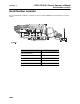
JT100/JT100 All Terrain Operator’s Manual Overview - 2 Serial Number Location Serial Number Location Record serial numbers and date of purchase in spaces provided. Drilling unit serial number is located as shown.
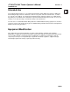
JT100/JT100 All Terrain Operator’s Manual Overview - 3 Intended Use Intended Use The JT100/JT100 All Terrain is a self-contained horizontal directional drilling unit capable of drilling and backreaming through solid rock, cobblestone, broken rock, gravel, and other soil/rock mixes, as well as less extreme soil conditions.
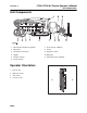
Overview - 4 JT100/JT100 All Terrain Operator’s Manual Unit Components Unit Components 1. Driver/loader attachment (optional) 7. Front and rear stabilizers 2. Pipeloader 8. Tracks 3. Front and rear wrenches 9. Operator’s station 4. Spindle 10. Drill frame 5. Rotation carriage 11. Anchoring system (optional) 6. Thrust carriage Operator Orientation 1 1. Front of unit 2. Right side of unit 3. Rear of unit 4. Left side of unit 2 4 3 j28om097t.
JT100/JT100 All Terrain Operator’s Manual Overview - 5 About This Manual About This Manual This manual contains information for the proper use of this machine. See the beige Operation Overview pages for basic operating procedures. Cross references such as “See page 50” will direct you to detailed procedures. Bulleted Lists Bulleted lists provide helpful or important information or contain procedures that do not have to be performed in a specific order.
Overview - 6 CMW© JT100/JT100 All Terrain Operator’s Manual
JT100/JT100 All Terrain Operator’s Manual Foreword - 7 Foreword This manual is an important part of your equipment. It provides safety information and operation instructions to help you use and maintain your Ditch Witch® equipment. Read this manual before using your equipment. Keep it with the equipment at all times for future reference. If you sell your equipment, be sure to give this manual to the new owner. If you need a replacement copy, contact your Ditch Witch dealer.
Foreword - 8 JT100/JT100 All Terrain Operator’s Manual JT100/JT100 All Terrain (Tier 4i) Operator’s Manual Issue number 1.0/OM-3/14 Part number 053-2546 Copyright 2014 by The Charles Machine Works, Inc. , Ditch Witch, Jet Trac, Fluid Miser, Power Pipe, and CMW are registered trademarks of The Charles Machine Works, Inc.
JT100/JT100 All Terrain Operator’s Manual Contents - 9 Contents Overview 1 machine serial number, information about the type of work this machine is designed to perform, basic machine components, and how to use this manual Foreword 7 part number, revision level, and publication date of this manual, and factory contact information Safety 11 machine safety alerts and emergency procedures Controls 27 machine controls, gauges, and indicators and how to use them Operation Overview 71 an overview
Contents - 10 JT100/JT100 All Terrain Operator’s Manual Specifications 231 machine specifications including weights, measurements, power ratings, and fluid capacities Support 239 the warranty policy for this machine, and procedures for obtaining warranty consideration and training Service Record a record of major service performed on the machine CMW© 237
JT100/JT100 All Terrain Operator’s Manual Safety - 11 Safety Chapter Contents Guidelines . . . . . . . . . . . . . . . . . . . . . . . . . . . . . . . . 12 Emergency Procedures . . . . . . . . . . . . . . . . . . . . . 13 • Electric Strike Description . . . . . . . . . . . . . . . . . . . . . . . . . . . . . . . . . . . 13 • If an Electric Line is Damaged . . . . . . . . . . . . . . . . . . . . . . . . . . . . . . . 14 • If a Gas Line is Damaged . . . . . . . . . . . . . . . . . . . . . . . . . . . .
Safety - 12 JT100/JT100 All Terrain Operator’s Manual Guidelines Guidelines Follow these guidelines before operating any jobsite equipment: • Complete proper training and read operator’s manual before using equipment. • Contact your local One-Call (811 in USA) or the One-Call referral number (888-258-0808 in USA and Canada) to have underground utilities located before digging. Also contact any utilities that do not participate in the One-Call service.
JT100/JT100 All Terrain Operator’s Manual Safety - 13 Emergency Procedures Emergency Procedures Jobsite hazards could cause death or serious injury. Use correct equipment and work methods. Use and maintain proper safety equipment. Before operating any equipment, review emergency procedures and check that all safety precautions have been taken. EMERGENCY SHUTDOWN - Turn ignition switch to stop position or push remote engine stop button (if equipped). Electric Strike Description Electric shock.
Safety - 14 JT100/JT100 All Terrain Operator’s Manual Emergency Procedures If an Electric Line is Damaged If you suspect an electric line has been damaged and you are on drilling unit or bonded equipment, DO NOT MOVE. Remain on drilling machine and take the following actions. The order and degree of action will depend on the situation. • Warn people nearby that an electric strike has occurred. • Have someone contact electric company. • Reverse drilling direction and try to break contact.
JT100/JT100 All Terrain Operator’s Manual Safety - 15 Emergency Procedures If a Gas Line is Damaged Fire or explosion possible. Fumes could ignite and cause burns. No smoking, no flame, no spark. Explosion possible. Serious injury or equipment damage could occur. Follow directions carefully. If you suspect a gas line has been damaged, take the following actions. The order and degree of action will depend on the situation. • Immediately shut off engine(s), if this can be done safely and quickly.
Safety - 16 JT100/JT100 All Terrain Operator’s Manual Emergency Procedures If a Fiber Optic Cable is Damaged Do not look into cut ends of fiber optic or unidentified cable. Vision damage can occur. Contact utility company. If Machine Catches on Fire Perform emergency shutdown procedure and then take the following actions. The order and degree of action will depend on the situation. • Immediately move battery disconnect switch (if equipped and accessible) to disconnect position.
JT100/JT100 All Terrrain Operator’s Manual Safety - 17 Driver/Loader Precautions Driver/Loader Precautions Intended Use The driver/loader is to be used for driving anchors and loading and unloading pipe boxes only. Use in any other way is considered contrary to the intended use. Preparation Visually inspect driver/loader each day to determine that it is in good condition before it is used. Check the following: • Make sure driver/loader is free of excess oil, grease, mud and debris before operation.
JT100/JT100 All Terrrain Operator’s Manual Safety - 18 Driver/Loader Precautions Operation General Riding on boom or load will result in death or serious injury. No riders. Keep off. • Never place chain link on tip of hook to lift load. • Close hook throat before lifting load. • Never use a sling bar or anything larger than the hook throat that could prevent hook latch from closing. This prevents damage to material being hoisted and helps prevent injury to personnel.
JT100/JT100 All Terrrain Operator’s Manual Safety - 19 Driver/Loader Precautions • Never swing a load over people. • Consider overall height of unit when moving under objects with low overhead clearance. • Operate controls smoothly and do not stop load sharply in midair so that it swings. • Fluid pressure from broken hydraulic line could pierce skin and cause injury or death. Stay away. • Keep loader/driver boom length as short as possible for maximum lifting capacity and safety.
JT100/JT100 All Terrrain Operator’s Manual Safety - 20 Driver/Loader Precautions Near Electrical Power Lines Do not get boom near power lines. Death or serious injury will occur. Keep required distance between boom and power lines. Use a spotter. Never operate the driver/loader within 10’ (3 m) of electric power lines carrying up to 50 kV. Add 1’ (305 mm) of clearance for each additional 30 kV or less (see table on left). Follow OSHA or other guidelines for working around power lines.
JT100/JT100 All Terrrain Operator’s Manual Safety - 21 Safety Alert Classifications Safety Alert Classifications These classifications and the icons defined on the following pages work together to alert you to situations which could be harmful to you, jobsite bystanders or your equipment. When you see these words and icons in the book or on the machine, carefully read and follow all instructions. YOUR SAFETY IS AT STAKE. Watch for the three safety alert levels: DANGER, WARNING and CAUTION.
Safety - 22 JT100/JT100 All Terrrain Operator’s Manual Machine Safety Alerts Machine Safety Alerts CMW©
JT100/JT100 All Terrrain Operator’s Manual Safety - 23 Machine Safety Alerts 1 Moving tools will kill or injure. Shut off drill string power when anyone can be struck by moving or thrown tools. Never use pipe wrenches on drill string. Moving parts could cut off hand. Keep hands away. 2 Turning shaft will kill you or crush arm or leg. Stay 3 4 5 6 7 away. Read operator’s manual. Know how to use all controls. Your safety is at stake. Jobsite hazards could cause death or serious injury.
Safety - 24 JT100/JT100 All Terrrain Operator’s Manual Machine Safety Alerts Hot parts may cause burns. Do not touch until cool 9 10 11 12 CMW© or wear gloves. Fire or explosion possible. Fumes could ignite and cause burns. No smoking, no flame, no spark. Crushing weight could cause death or serious injury. Use proper procedures and equipment or stay away. Fall possible. Riders can fall from machine and be injured or killed. Only operator is allowed on machine.
JT100/JT100 All Terrrain Operator’s Manual Safety - 25 Attachment Safety Alerts Attachment Safety Alerts Driver/Loader Attachment 1 Riding on boom or load will result in death or serious injury. No riders. Keep off. Moving parts could cut off hand. Keep hands away. 2 3 Read operator’s manual. Know how to use all controls. Your safety is at stake.
Safety - 26 JT100/JT100 All Terrrain Operator’s Manual Attachment Safety Alerts 4 5 CMW© Do not get boom near power lines. Death or serious injury will occur. Keep required distance between boom and power lines. Use a spotter. Auxiliary stabilizer must be properly installed with contact on firm surface before operating pipebox loader on the engine side of the unit. Working loads should be limited to those shown.
JT100/JT100 All Terrain Operator’s Manual Controls - 27 Controls Chapter Contents Set-Up Console . . . . . . . . . . . . . . . . . . . . . . . . . . . 28 Tethered Driver/Loader Controller . . . . . . . . . . . . 31 Overhead Console . . . . . . . . . . . . . . . . . . . . . . . . . 34 Left Control Console . . . . . . . . . . . . . . . . . . . . . . . 36 • Pipeloading Controls . . . . . . . . . . . . . . . . . . . . . . . . . . . . . . . . . . . . . . 36 • Drilling Controls . . . . . . . . . . . . . . .
Controls - 28 JT100/JT100 All Terrain Operator’s Manual Setup Console Setup Console 1. Engine throttle switch 6. Left front stabilizer control 2. Remote engine stop switch 7. Right front stabilizer control 3. Auxiliary light switch 8. Auxiliary hydraulic pressure gauge 4. Left rear stabilizer control 9. Levels 5. Right rear stabilizer control Item Description Notes 1.
JT100/JT100 All Terrain Operator’s Manual Controls - 29 Setup Console Item Description Notes 2. Remote engine stop switch To stop engine, press. IMPORTANT: To restart engine, turn ignition off and then back to start. • If this switch is used to stop drilling unit, be sure to turn ignition switch off if machine will be left unattended for long periods of time. Battery discharge can occur. • If wrenches are engaged when remote stop is pressed, wrenches will remain engaged but could gradually open.
Controls - 30 JT100/JT100 All Terrain Operator’s Manual Setup Console Item Description Notes 6. Left front stabilizer control To lower, push. Lower both front stabilizers to the ground together and then adjust individually. To raise, pull. 7. Right front stabilizer control To lower, push. To raise, pull. 8.
JT100/JT100 All Terrain Operator’s Manual Controls - 31 Tethered Driver/Loader Control Tethered Driver/Loader Control 1 8 3 4 2 7 6 5 9 j28om013t.eps 1. Power switch 6. Driver/Loader arm swing control switch 2. Remote engine stop switch 7. Outer boom control switch 3. Auxiliary control switch 8. Inner boom control switch 4. Anchor driver control switch 9. Speed control 5.
Controls - 32 JT100/JT100 All Terrain Operator’s Manual Tethered Driver/Loader Control Item Description 1. Power switch To turn on power to driver/ loader, push to left. Notes To turn off power to driver/ loader, push to right. 2. Remote engine stop switch To stop engine, push to right. 3. Auxiliary control switch Not used. 4. Anchor driver control switch To drive anchor (rotate clockwise), push up and press speed control.
JT100/JT100 All Terrain Operator’s Manual Controls - 33 Tethered Driver/Loader Control Item Description 6. Outer boom control switch To lower, push up and press speed control. Notes To raise, push down and press speed control. To stop, release switch or speed control. 7. Loader/Driver arm swing control switch To swing counterclockwise, push to left and press speed control. IMPORTANT: Arm will not swing more than 360°. To swing clockwise, push to right and press speed control.
JT100/JT100 All Terrain Operator’s Manual Controls - 34 Overhead Console Overhead Console 1. Light switch 3. Lower windshield wiper switch 2. Upper windshield wiper switch 4. Cab pivot control switch Item Description 1. Light switch To turn on, press To turn off, press 2. Upper windshield wiper switch To spray wiper fluid on windshield, press To start wiper blade, move to center. To stop wiper blade, press c00ic051t.
JT100/JT100 All Terrain Operator’s Manual Controls - 35 Overhead Console Item Description 3. Lower windshield wiper switch To spray wiper fluid on windshield, press Notes To start wiper blade, move to center. To stop wiper blade, press c00ic052t.eps 4. Cab pivot control switch To move cab into drilling position, disengage cab pivot lock and press See “Cab pivot lock” on page 44 for more information.
JT100/JT100 All Terrain Operator’s Manual Controls - 36 Left Control Console Left Control Console Pipeloading Controls 1. Shuttle stop switch 7. Back frame tilt switch 2. Add pipe/manual/remove pipe switch 8. Pipe lubricator switch 3. Pipe lift switch 9. Front wrench clamp switch 4. Pipe gripper switch 10. Rear wrench clamp switch 5. Pipe shuttle switch 11. Rear wrench rotation switch 6. Front frame tilt switch Item Description Notes 1.
JT100/JT100 All Terrain Operator’s Manual Controls - 37 Left Control Console Item Description Notes 2. Add pipe/manual/ remove pipe switch To select “add pipe” automated pipeloader function, press green part of switch. See “Add Pipe” on page 122. To use manual pipeloader controls, move to center. See “Remove Pipe” on page 130. c00ic059t.eps 3. Pipe lift switch To select “remove pipe” automated pipeloader function, press white part of switch. To lower, press To raise, press 4.
Controls - 38 JT100/JT100 All Terrain Operator’s Manual Left Control Console Item Description 10. Rear wrench clamp switch To unclamp, press To clamp, press 11. Rear wrench rotation switch To rotate counterclockwise, press To rotate clockwise, press To stop rotation, release.
JT100/JT100 All Terrain Operator’s Manual Controls - 39 Left Control Console JT Drilling Controls 1. Spindle brake switch 3. Rotation speed control 2. Set/resume switch 4. Rotation tachometer Item Description Notes 1. Spindle brake switch To engage, press IMPORTANT: Use when making directional change. To disengage, press c00ic053t.eps 2. Set/resume switch To resume operation or increase operation levels, press green part of switch. See “Cruise Control” on page 172.
Controls - 40 JT100/JT100 All Terrain Operator’s Manual Left Control Console Item Description 3. Rotation speed control To increase, turn clockwise. To decrease, turn counterclockwise. 4. Rotation tachometer CMW© Displays spindle speed.
JT100/JT100 All Terrain Operator’s Manual Controls - 41 Left Control Console AT Drilling Controls 1. Outer spindle brake switch 6. Inner rotation pressure gauge 2. Set/resume switch 7. Inner rotation speed control 3. Outer rotation speed control 8. Manual inner rotation switch 4. Outer spindle tachometer 9. Inner spindle switch 5. Inner spindle tachometer Item Description Notes 1. Outer spindle brake switch To engage, press IMPORTANT: Use when making directional change.
Controls - 42 JT100/JT100 All Terrain Operator’s Manual Left Control Console Item Description Notes 2. Set/resume switch To resume operation or increase operation levels, press green part of switch. See “Cruise Control” on page 172. To set operating conditions or reduce operation levels, press white part of switch. c00ic054t.eps 3. Outer rotation speed control To increase, turn clockwise. To decrease, turn counterclockwise. 4. Outer spindle tachometer Displays outer spindle speed. 5.
JT100/JT100 All Terrain Operator’s Manual Controls - 43 Left Control Console Item Description 6. Inner spindle rotation pressure gauge Displays inner spindle rotation pressure. Notes psi x 1000 3 4 2 2 3 1 5 1 0 0 bar x 100 4 6 c00ic088t.eps 7. Inner rotation speed control To increase, turn clockwise. To decrease, turn counterclockwise. 8. Manual inner rotation switch To rotate counterclockwise, move switch to left. IMPORTANT: Inner spindle switch must be in manual position.
Controls - 44 JT100/JT100 All Terrain Operator’s Manual Left Control Console Operation Controls 1. Cab pivot lock 4. Fluid flow control 2. Engine throttle switch 5. Drill/drive selector 3. Horn Item Description Notes 1. Cab pivot lock To move cab into drilling position, press down and pivot cab into position. See “Cab pivot control switch” on page 35 for more information. Lock automatically engages when cab moves into drive position. 2.
JT100/JT100 All Terrain Operator’s Manual Controls - 45 Left Control Console Item Description 3. Horn To sound horn, press. 4. Fluid flow control To increase flow, turn clockwise. Notes To decrease flow, turn counterclockwise. 5. Drill/drive selector To drill, press To set parking brake, move to center. To drive, press c00ic055t.
JT100/JT100 All Terrain Operator’s Manual Controls - 46 Left Control Console Climate Controls 1. Climate fan speed selector 3. Heater temperature control 2. Climate control control selector 4. Air conditioner temperature control Item Description 1. Climate control fan speed selector To select high fan speed, press To select medium speed, move to center. To select low speed, press 2. Climate control selector To start heater, press To turn climate control off, move to center.
JT100/JT100 All Terrain Operator’s Manual Controls - 47 Left Control Console Item Description 3. Heater temperature control To make air warmer, turn clockwise. Notes To make air cooler, turn counterclockwise. 4. Air conditioner temperature control To make air cooler, turn clockwise. To make air warmer, turn counterclockwise.
JT100/JT100 All Terrain Operator’s Manual Controls - 48 Right Control Console Right Control Console Engine Display 1. Tachometer 7. Soft key 2. Drilling fluid flow display 8. Main menu key 3. Hour meter 9. Soft key 4. Engine coolant temperature gauge 10. Day/Night mode key 5. Engine oil pressure gauge 11. Voltmeter display 6. DPF regen mode key 12. Fuel gauge Item Description 1. Tachometer Displays engine speed. 2.
JT100/JT100 All Terrain Operator’s Manual Controls - 49 Right Control Console Item Description Notes 4. Engine coolant temperature gauge Displays engine coolant temperature. Normal coolant temperature is 180°230° F (82°-110° C). 5. Engine oil pressure gauge Displays engine oil pressure. Full load reading should be 60-80 psi (4.1-5.5 bar). 6. DPF regen mode key Toggles between automatic (ECU-controlled) and inhibited DPF regeneration modes.
Controls - 50 JT100/JT100 All Terrain Operator’s Manual Right Control Console Item Description Notes 8. Main screen key Press to return to main screen (gauges). 7. Engine diagnostics key Press to select engine diagnostics menu. For dealer technician use only. 6. System operating info Press to show combined system information screen. For dealer technician use only. Status Indicators Indicators CMW© DPF Regen inhibited See engine manual.
JT100/JT100 All Terrain Operator’s Manual Controls - 51 Right Control Console Gauges and Indicators 1. Drilling fluid pressure gauge 3. Rotation pressure gauge 2. Thrust pressure gauge 4. Engine display Item Description Notes 1. Drilling fluid pressure gauge Displays discharge pressure of drilling fluid pump. IMPORTANT: Monitor this gauge and drilling fluid flowmeter carefully to see if values are rising or falling at the same time. If they are not, nozzle might be plugged. 2.
Controls - 52 JT100/JT100 All Terrain Operator’s Manual Right Control Console Item Description 3. Rotation pressure gauge Displays hydraulic fluid pressure to rotation motor when spindle is turning. 4. Engine display Displays engine speed, engine data and diagnostic codes. CMW© Notes See “Engine Display” on page 178 and “Engine Diagnostic Codes” on page 177 for more information.
JT100/JT100 All Terrain Operator’s Manual Controls - 53 Right Control Console Lights 1. Control cycle light (green) 5. Front home status light 2. Diagnostic light (red) 6. Front wrench status light 3. Shuttle home status light 7. Drilling fluid pump status light 4. Rear home status light Item Description 1. Control cycle light (green) If nothing is being controlled, light is off. Notes If system is waiting for an action before starting cycle, light flashes on and off.
Controls - 54 JT100/JT100 All Terrain Operator’s Manual Right Control Console Item Description 2. Diagnostic light (red) If system is OK, light is off. Notes If controller is not getting power, light is on. If a non-essential diagnostic code is recorded, light flashes on and off for 10 seconds. See “Diagnostic Codes” on page 173. If an essential diagnostic code is recorded, light continually flashes on for three seconds and off for half a second. 3.
JT100/JT100 All Terrain Operator’s Manual Controls - 55 Right Control Console Item Description 6. Front wrench status light If front wrench is closed and pressured up, light is on. Notes If front wrench is open or pressure has dropped, light is off. 7. Drilling fluid pump status light If pump is on, light is on. If pump is off, light is off.
Controls - 56 JT100/JT100 All Terrain Operator’s Manual Right Control Console Controls 1. Dual speed carriage control 5. Shutdown override switch 2. Drilling fluid quick fill switch 6. Ignition switch 3. Drilling fluid pump switch 7. Remote engine stop switch 4. Track and carriage control Item Description Notes 1. Dual speed carriage control To increase carriage travel speed, push and hold. Use during bore or pullback when no pipe is in spindle to save time.
JT100/JT100 All Terrain Operator’s Manual Controls - 57 Right Control Console Item Description 2. Drilling fluid quick fill switch For full pump flow to fill pipe with fluid, press and hold. Notes To return fluid flow to flow control setting, release. 3. Drilling fluid pump switch To turn on, press once. IMPORTANT: To adjust flow, see “Fluid flow control” on page 45. To turn off, press once. 4. Track and carriage control Track control: IMPORTANT: • To move forward, push.
Controls - 58 JT100/JT100 All Terrain Operator’s Manual Right Control Console Item Description 5. Shutdown override switch Temporarily override engine shutdown, press and hold Notes c00ic056t.eps 6. Ignition switch To start engine, insert key and turn clockwise. IMPORTANT: Restart engine with ignition switch after it has been turned off with remote engine stop switch. To stop engine, turn key counterclockwise. 7. Remote engine stop switch To stop engine, press.
JT100/JT100 All Terrain Operator’s Manual Controls - 59 Fluid Pump Fluid Pump 1 2 3 j17om089t.eps 1. Light switch 3. Fluid pressure gauge 2. Wash wand switch Item Description Notes 1. Light switch To turn on, press Controls light at fluid pump work station.
Controls - 60 JT100/JT100 All Terrain Operator’s Manual Fluid Pump Item Description 2. Wash wand switch To spray, press To turn off, press c00ic058t.eps 3. Fluid pressure gauge CMW© Displays drilling fluid pressure supplied to the pump.
JT100/JT100 All Terrain Operator’s Manual Controls - 61 JT/AT System JT/AT System 1. Mode selector switch 2. Inner rotation hourmeter Item Description Notes 1. Mode selector switch To select AT mode, press left. Use AT or AT DIRT drilling mode when using AT pipe with inner shaft. To select AT DIRT mode, move to center. To select JT mode, press right. 2. Inner rotation hourmeter Displays inner rotation operating time. Use JT drilling mode when using JT pipe without inner shaft.
JT100/JT100 All Terrain Operator’s Manual Controls - 62 Seat Seat 2 1 j07om045h.eps 1. Seat slide control 2. Seat recline control Item Description 1. Seat slide control To slide forward or backward, move left. To lock seat in position, move right. 2. Seat recline control To recline or raise seatback, lift. To lock seatback in position, release.
JT100/JT100 All Terrain Operator’s Manual Controls - 63 Emergency Exit Emergency Exit Push rear window out and exit to rear of cab. Override Box 1. Drive override connector 4. Thrust/pullback or right track override switch 2. Drill override connector 5. Rotation or left track override switch 3. Drilling fluid flow override switch Item Description Notes 1. Drive override connector Allows drive function override when box is attached. Use switches 4 and 5 to control tracks. 2.
Controls - 64 JT100/JT100 All Terrain Operator’s Manual Override Box Item Description Notes 4. Thrust/pullback or right track override switch For thrust or to move track forward, move up. Connect to drill connector (2) to control thrust/pullback. For pullback or to move track backward, move down. Connect to drive connector (1) to control right track. For counterclockwise rotation or to move track forward, move up. Connect to drill connector (2) to control rotation. 5.
JT100/JT100 All Terrain Operator’s Manual Controls - 65 Miscellaneous Controls Miscellaneous Controls 1 3 2 1 j28om014t.eps Item Description Notes 1. Auxiliary outlets Supplies power to work lights or other 12V devices. Outlet has power only when ignition switch is on. 2. Auxiliary outlet Supplies power to 12V devices. 3. Driver/Loader enable switch To enable, press Enables tethered driver/loader controls to function. To disable, press IMPORTANT: Disable driver/loader when not in use.
Controls - 66 JT100/JT100 All Terrain Operator’s Manual Engine Diagnostic Connector Engine Diagnostic Connector Item Description Engine diagnostic connector Connects diagnostic test equipment to unit.
JT100/JT100 All Terrain Operator’s Manual Controls - 67 Battery Battery Item Description Notes Battery disconnect switch To connect, move switch so that indicator points right. Use when servicing unit and during long-term storage. To disconnect, move switch so that indicator points left.
JT100/JT100 All Terrain Operator’s Manual Controls - 68 ESID ESID 2 3 1 4 5 6 7 8 j07om042h.eps 1. Alphanumeric display 5. Current problem indicator 2. Strike indicator 6. OK indicator 3. Alarm interrupt button 7. Electrical power supply indicator 4. Voltage problem indicator 8. Self test button Item Description 1. Alphanumeric display Display amount of current and voltage being detected as a percentage of strike condition.
JT100/JT100 All Terrain Operator’s Manual Controls - 69 ESID Item Description Notes 3. Alarm interrupt button To turn off strike alarm at drilling unit, press. 4. Voltage problem indicator Red light indicates a voltage indicator problem. See “Troubleshoot Strike System” on page 148. 5. Current problem indicator Red light indicates a current indicator problem. See “Troubleshoot Strike System” on page 148. 6. OK indicator Green light means system self test detected no problems.
Controls - 70 JT100/JT100 All Terrain Operator’s Manual ESID Item Description 7. Electrical power supply indicator Green light means control box has sufficient electrical power for operation. Notes Strike system is operating if OK indicator is also on. 8. Self test button CMW© To start manual self test, press. Checks all systems and circuits except voltage limiter. To reset system after a strike has been detected, press. NOTICE: See “If an Electric Line is Damaged” on page 18.
JT100/JT100 All Terrain Operator’s Manual Operation Overview - 71 Operation Overview Chapter Contents Planning. . . . . . . . . . . . . . . . . . . . . . . . . . . . . . . . . . 72 Setting Up at Jobsite . . . . . . . . . . . . . . . . . . . . . . . 72 Drilling . . . . . . . . . . . . . . . . . . . . . . . . . . . . . . . . . . . 73 Backreaming . . . . . . . . . . . . . . . . . . . . . . . . . . . . . . 74 Leaving Jobsite. . . . . . . . . . . . . . . . . . . . . . . . . . . . 74 Storing Equipment . . . . .
Operation Overview - 72 JT100/JT100 All Terrain Operator’s Manual Planning Planning 1. Gather information about jobsite. See page 77. 2. Inspect jobsite. See page 78. 3. Classify jobsite. See page 80. 4. Plan bore path. See page 83. 5. Check supplies and prepare equipment. See page 95. 6. Load equipment. See page 107. Setting Up at Jobsite 1. Prepare jobsite. See page 94. 2. Unload drilling unit from trailer. See page 109. 3. Assemble drill string. See page 117. 4. Position drilling unit and frame.
JT100/JT100 All Terrain Operator’s Manual Operation Overview - 73 Drilling Drilling 1. Start system. See page 114. 2. Engage tracker control if desired. See page 157. 3. Drill first pipe. See page 120. • JT mode • AT dirt mode • AT mode 4. Swab the hole to remove cuttings (AT mode only). See page 121. 5. Record bore path. See page 126. 6. Enable automated pipeloader system. See page 121. 7. Add pipe. See page 122. 8. Drill remaining pipes in pipe box. • Correct direction. See page 124.
Operation Overview - 74 JT100/JT100 All Terrain Operator’s Manual Backreaming Backreaming 1. Assemble backream string. See page 128. 2. Start drilling unit and adjust throttle. 3. Set drilling fluid flow. Check that fluid flows through all nozzles. See page 160. 4. Remove pipe from bore. See page 130. 5. Remove full pipe box and add empty box (see page 139) to complete backream. 6. Remove pullback device. See page 132. Backreaming Tips • Plan backreaming job before drilling.
JT100/JT100 All Terrain Operator’s Manual Prepare - 75 Prepare Chapter Contents Gather Information . . . . . . . . . . . . . . . . . . . . . . . . . 77 • Review Job Plan . . . . . . . . . . . . . . . . . . . . . . . . . . . . . . . . . . . . . . . . . . 77 • Notify One-Call Services . . . . . . . . . . . . . . . . . . . . . . . . . . . . . . . . . . . . 77 • Examine Pullback Material . . . . . . . . . . . . . . . . . . . . . . . . . . . . . . . . . . 77 • Arrange for Traffic Control. . . . . . . .
Prepare - 76 JT100/JT100 All Terrain Operator’s Manual Prepare Jobsite . . . . . . . . . . . . . . . . . . . . . . . . . . . . 94 • Mark Bore Path . . . . . . . . . . . . . . . . . . . . . . . . . . . . . . . . . . . . . . . . . . . 94 • Prepare Entry Point. . . . . . . . . . . . . . . . . . . . . . . . . . . . . . . . . . . . . . . . 94 Check Supplies and Prepare Equipment . . . . . . . 95 • Check Supplies . . . . . . . . . . . . . . . . . . . . . . . . . . . . . . . . . . . . . . . . . . .
JT100/JT100 All Terrain Operator’s Manual Prepare - 77 Gather Information Gather Information A successful job begins before the bore. The first step in planning is reviewing information already available about the job and jobsite. Review Job Plan Review blueprints or other plans and make sure you have taken bore enlargement during backreaming and pullback into account. Check for information about existing or planned structures, elevations, or proposed work that may be taking place at the same time.
Prepare - 78 JT100/JT100 All Terrain Operator’s Manual Inspect Site Inspect Site Inspect jobsite before transporting equipment. Check for the following: • overall grade or slope • changes in elevation such as hills or open trenches • obstacles such as buildings, railroad crossings, or streams • signs of utilities (See “Inspect Jobsite” on page 80.) • traffic • access • soil type and condition • water supply • sources of locator interference (rebar, railroad tracks, etc.
JT100/JT100 All Terrain Operator’s Manual Prepare - 79 Inspect Site Select Start and End Points Select one end to use as a starting point. Consider the following when selecting a starting point: Slope Fluid system should be parked on a level site. Consider how slope will affect drilling unit setup, bending pipe, and fluid flow out of hole. Traffic Vehicle and pedestrian traffic must be a safe distance from drilling equipment. Allow at least 10’ (3 m) buffer zone around equipment.
Prepare - 80 JT100/JT100 All Terrain Operator’s Manual Classify Jobsite Classify Jobsite Inspect Jobsite • Follow U.S. Department of Labor regulations on excavating and trenching (Part 1926, Subpart P) and other similar regulations. • Contact your local One-Call (811 in USA) or the One-Call referral number (888-258-0808 in USA and Canada) to have underground utilities located before digging. Also contact any utilities that do not participate in the One-Call service.
JT100/JT100 All Terrain Operator’s Manual Prepare - 81 Classify Jobsite Apply Precautions Once classified, precautions appropriate for jobsite must be taken. Electric Jobsite Precautions Electric shock will cause death or serious injury. Stay away. In addition to using a directional drilling system with an electric strike system, use one or both of these methods. • Expose line by careful hand digging or soft excavation. Use beacon to track bore path.
Prepare - 82 JT100/JT100 All Terrain Operator’s Manual Classify Jobsite Crystalline Silica (Quartz) Dust Precautions Use breathing protection when exposed to silica dust. Follow OSHA or other guidelines for exposure to crystalline silica when trenching, sawing or drilling through material that might produce dust containing crystalline silica (quartz). Other Jobsite Precautions You may need to use different methods to safely avoid other underground hazards.
JT100/JT100 All Terrain Operator’s Manual Prepare - 83 Plan Bore Path Plan Bore Path Plan the bore path, from entry to end, before drilling begins. The Ditch Witch® Trac Management System Plus is available for planning your bore path. This special software can be run in the field using a laptop computer equipped with Windows® 95 or higher operating system. See your Ditch Witch dealer for details.
Prepare - 84 JT100/JT100 All Terrain Operator’s Manual Plan Bore Path Recommended Bend Limits Ditch Witch drill pipes are designed to bend slightly during operation. Slight bending allows for steering and correcting direction. Bending beyond recommended limits will cause damage that might not be visible. This damage adds up and will later lead to sudden drill pipe failure. IMPORTANT: Consider recommended bend limits during any bend, not just during bore entry.
JT100/JT100 All Terrain Operator’s Manual Prepare - 85 Plan Bore Path Bend Radius JT100 Power Pipe® drill pipes have a tested minimum bend radius of 205’ (62.5 m). This means that a 90° bend in the bore path: • has a radius (A) of 205’ (62.5 m) • requires approximately 325’ (99 m) of drill pipe (B). JT100 Power Pipe Forged drill pipes have a tested minimum bend radius of 197’ (60 m). This means that a 90° bend in the bore path: • has a radius (A) of 197’ (60 m) • requires approximately 310’ (94.
JT100/JT100 All Terrain Operator’s Manual Prepare - 86 Plan Bore Path Pipe-By-Pipe Bend Limits - Power Pipe® Pipe (C) Forward (B) Deflection (A) Pipe (C) Forward (B) Deflection (A) 1 14 ft 9 in (4.5 m) 0 ft 6 in (0.2 m) 12 155 ft 11 in (47.5 m) 71 ft 11 in (21.9 m) 2 29 ft 5 in (9.0 m) 2 ft 1 in (0.6 m) 13 165 ft 1 in (50.3 m) 83 ft 6 in (25.4 m) 3 43 ft 11 in (13.4 m) 4 ft 9 in (1.5 m) 14 173 ft 5 in (52.9 m) 95 ft 8 in (29.2 m) 4 58 ft 3 in (17.8 m) 8 ft 5 in (2.
JT100/JT100 All Terrain Operator’s Manual Prepare - 87 Plan Bore Path Pipe-By-Pipe Bend Limits - Power Pipe® Forged Pipe (C) Forward (B) Deflection (A) Pipe (C) Forward (B) Deflection (A) 1 0 ft 7 in (0.2 m) 14 ft 12 in (4.6 m) 12 76 ft 8 in (23.4 m) 155 ft 12 in (47.5 m) 2 2 ft 3 in (0.7 m) 29 ft 11 in (9.1 m) 13 88 ft 11 in (27.1 m) 164 ft 8 in (50.2 m) 3 5 ft 1 in (1.6 m) 44 ft 7 in (13.6 m) 14 101 ft 9 in (31 m) 172 ft 5 in (52.6 m) 4 9 ft 1 in (2.
JT100/JT100 All Terrain Operator’s Manual Prepare - 88 Plan Bore Path Pipe-By-Pipe Bend Limits - All Terrain Pipe Pipe (C) Forward (B) Deflection (A) Pipe (C) Forward (B) Deflection (A) 1 14 ft 1 in (4.3 m) 0 ft 6 in (0.1 m) 13 160 ft 0 in (48.8 m) 76 ft 11 in (23.4 m) 2 28 ft 2 in (8.6 m) 1 ft 11 in (0.6 m) 14 168 ft 6 in (51.4 m) 88 ft 2 in (26.9 m) 3 42 ft 1 in (12.8 m) 4 ft 4 in (1.3 m) 15 176 ft 1 in (53.7 m) 100 ft 1 in (30.5 m) 4 55 ft 9 in (17.0 m) 7 ft 9 in (2.
JT100/JT100 All Terrain Operator’s Manual Prepare - 89 Plan Bore Path Entry Pitch Entry pitch is the slope of the drill frame compared with the slope of the ground. Determine entry pitch one of two ways: 1. With Pitch Beacon • Lay pitch beacon on the ground and read pitch. • Lay pitch beacon on drill frame and read pitch. • Subtract ground pitch from drilling unit pitch. 2. With Measurements • Measure from the ground to front end of drill frame (H1).
Prepare - 90 JT100/JT100 All Terrain Operator’s Manual Plan Bore Path Minimum Setback Setback is the distance from the entry point to where pipe becomes horizontal (B1). NOTICE: If setback is too small (B2), you will exceed bend limits and damage the pipe. Minimum Depth Because you must bend pipe gradually, entry pitch and bend limits determine how deep the pipe will be when it becomes horizontal. This is called the minimum depth. • To reduce minimum depth (D1), reduce entry pitch.
JT100/JT100 All Terrain Operator’s Manual Prepare - 91 Plan Bore Path Bore Path Calculator - Power Pipe® Entry pitch, setback, and minimum depth work together with bend limits to determine the bore path. To find the setback (B) and entry pitch (A) that will take you to the desired minimum depth (D), use the chart below. Minimum depth (D) Entry pitch (A) Setback (B) Depth to begin steering (S) 6 ft 10 in (2.08 m) 11.3° / -20% 54 ft 6 in (16.61 m) 2 ft 10 in (0.86 m) 7 ft 11 in (2.41 m) 12.
JT100/JT100 All Terrain Operator’s Manual Prepare - 92 Plan Bore Path Bore Path Calculator - Power Pipe® Forged Entry pitch, setback, and minimum depth work together with bend limits to determine the bore path. To find the setback (B) and entry pitch (A) that will take you to the desired minimum depth (D), use the chart below. Minimum depth (D) Entry pitch (A) Setback (B) Depth to begin steering (S) 5 ft 3 in (1.52 m) 10.0° / -18% 46 ft 10 in (14.27 m) 2 ft 3 in (0.69 m) 6 ft 0 in (1.83 m) 10.
JT100/JT100 All Terrain Operator’s Manual Prepare - 93 Plan Bore Path Bore Path Calculator - All Terrain Pipe Entry pitch, setback, and minimum depth work together with bend limits to determine the bore path. To find the setback (B) and entry pitch (A) that will take you to the desired minimum depth (D), use the chart below. Minimum depth (D) Entry pitch (A) Setback (B) Depth to begin steering (S) 6 ft 7 in (2.01 m) 11.3° / -20% 53 ft 4 in (16.26 m) 2 ft 7 in (0.79 m) 7 ft 8 in (2.34 m) 12.
JT100/JT100 All Terrain Operator’s Manual Prepare - 94 Prepare Jobsite Prepare Jobsite Jobsite hazards could cause death or serious injury. Use correct equipment and work methods. Use and maintain proper safety equipment. To help avoid injury: • If jobsite classification is in question or if the possibility of unmarked electric utilities exists, classify jobsite as electric. • Expose lines by hand before digging. Cutting high voltage cable can cause electrocution.
JT100/JT100 All Terrain Operator’s Manual Prepare - 95 Check Supplies and Prepare Equipment Check Supplies and Prepare Equipment Check Supplies • receiver/transmitter or tracker with spare batteries • beacons with new and spare batteries • two-way radios with new and spare batteries • hydraulic wrench (see “Hydratong Wrenches” on page 165) • transition sub • anchoring equipment and accessories • bits, screens, nozzles (see “Downhole Tools” on page 160) • adapters, pipe, beacon housings •
Prepare - 96 JT100/JT100 All Terrain Operator’s Manual Check Supplies and Prepare Equipment Prepare Equipment Fluid Levels • fuel • hydraulic fluid • engine coolant • battery charge • engine oil Condition and Function • filters (air, oil, hydraulic) • fluid pump • couplers • tires and tracks • pumps and motors • drilling fluid mixer • hoses and valves • water tanks CMW©
JT100/JT100 All Terrain Operator’s Manual Prepare - 97 Check Supplies and Prepare Equipment Select Drilling Mode Three drilling setups are available with this unit: • AT mode • AT dirt mode • JT mode Select the best setup based on jobsite conditions. Mode Situation used Downhole tools Capabilities AT Rock, soft rock, other non-compressible soils. Any other situation with difficult steering because of hard soil conditions.
Prepare - 98 JT100/JT100 All Terrain Operator’s Manual Check Supplies and Prepare Equipment Prepare Drilling Unit AT Mode • Verify unit has not been converted to JT mode. Ensure All Terrain saver sub, shuttle stop, roller, and roller pin are installed. • Inspect Rockmaster™ tool and select bit based on jobsite conditions. • Use appropriate anchors for jobsite conditions. • Load All Terrain pipe and pipe box onto unit. • Move mode selector switch to AT position.
JT100/JT100 All Terrain Operator’s Manual Prepare - 99 JT Mode IMPORTANT: Use conversion kit (p/n 190-1548). • Install saver sub, shuttle stop, roller, and roller pin for Mach 1 pipe. • Use standard transition sub and beacon housing. Select soil bit based on jobsite conditions. • Use auger type anchors. • Load JT pipe and pipe box onto unit. IMPORTANT: Do not put JT pipe into a large All Terrain pipe box. Pipe can jam and box can be damaged. Use JT pipe box.
Prepare - 100 CMW© JT100/JT100 All Terrain Operator’s Manual
JT100/JT100 All Terrain Operator’s Manual Drive - 101 Drive Chapter Contents Start Unit . . . . . . . . . . . . . . . . . . . . . . . . . . . . . . . . 102 Steer Unit . . . . . . . . . . . . . . . . . . . . . . . . . . . . . . . 102 Shut Down Unit . . . . . . . . . . . . . . . . . . . . . . . . . .
Drive - 102 JT100/JT100 All Terrain Operator’s Manual Start Unit Start Unit 1. Insert key. 2. Turn key clockwise. See “Ignition switch” on page 58 for more information. Wait until start light goes out to crank engine. 3. Run engine at low throttle for 5 minutes. Steer Unit IMPORTANT: Operator’s station must be in drive position. See “Cab pivot control switch” on page 35. To steer drilling unit, follow instructions for type of steering desired.
JT100/JT100 All Terrain Operator’s Manual Drive - 103 Steer Unit Safe Slope Operation Tipover possible. Machine can tip over and crush you. • Always operate with heavy end uphill. • Drive cautiously at all times. • Never jerk control levers. Use a steady even motion. • Do not park unit on slope without lowering anchor frame to the ground, returning all controls to neutral position, shutting down unit, and applying parking brake.
Drive - 104 JT100/JT100 All Terrain Operator’s Manual Shut Down Unit Shut Down Unit 1. Stop track movement. 2. Move drill/drive selector to center position to engage parking brake. 3. Run engine at low throttle for 3 minutes to cool. 4. Turn key to STOP. 5. Remove key.
JT100/JT100 All Terrain Operator’s Manual Transport - 105 Transport Chapter Contents Lift . . . . . . . . . . . . . . . . . . . . . . . . . . . . . . . . . . . . . 106 Haul . . . . . . . . . . . . . . . . . . . . . . . . . . . . . . . . . . . . 107 • Load . . . . . . . . . . . . . . . . . . . . . . . . . . . . . . . . . . . . . . . . . . . . . . . . . . 107 • Tie Down . . . . . . . . . . . . . . . . . . . . . . . . . . . . . . . . . . . . . . . . . . . . . . 108 • Unload . . . . . . . . . . . . . . .
Transport - 106 JT100/JT100 All Terrain Operator’s Manual Lift Lift This machine is not configured for lifting. If the machine must be lifted, load machine into a container or onto a platform appropriate for lifting. See “Specifications” for weight of machine. Pipe Box Lifting Procedure Pipe box lifting points are identified by lifting decals. Lifting at other points is unsafe and can damage machinery.
JT100/JT100 All Terrain Operator’s Manual Transport - 107 Haul Haul Load Crushing weight. If load falls or moves it could kill or crush you. Use proper procedures and equipment or stay away. To help avoid injury: • Load and unload trailer on level ground. • Incorrect loading can cause trailer swaying. • Attach trailer to vehicle before loading or unloading. • Ten to fifteen percent of total vehicle weight (equipment plus trailer) must be on tongue to help prevent trailer sway. 1.
Transport - 108 JT100/JT100 All Terrain Operator’s Manual Haul Tie Down Points Tiedown points are identified by tiedown decals. Securing to trailer at other points is unsafe and can damage machinery. Procedure Ensure driver/loader is in stowed position and stow strap (2) is tight. Ensure anchor drive motor is in stowed position (1). Loop tiedowns around unit at tiedown points. Make sure tiedowns are tight before transporting.
JT100/JT100 All Terrain Operator’s Manual Transport - 109 Haul Unload Crushing weight. If load falls or moves it could kill or crush you. Use proper procedures and equipment or stay away. To help avoid injury: • Load and unload trailer on level ground. • Attach trailer to vehicle before loading or unloading. 1. Lower trailer or ramps. 2. Fasten and adjust seat belt. 3. Start drilling unit engine. 4. Remove tiedowns. 5. Raise drill frame. 6. Raise stabilizers. 7.
JT100/JT100 All Terrain Operator’s Manual Transport - 110 Tow Tow Under normal conditions, drilling unit should not be towed. If unit breaks down and towing is necessary: • tow for short distances at less than 1 mph (1.6 km/h), • attach chains to indicated tow points facing towing vehicle, • use maximum towing force of 1.5 times unit weight, • disengage track planetaries. To disengage track planetaries, reverse small cover plate in center of planetary on each track drive.
JT100/JT100 All Terrain Operator’s Manual Conduct a Bore - 111 Conduct a Bore Chapter Contents Position Equipment . . . . . . . . . . . . . . . . . . . . . . . 113 Connect Fluid System . . . . . . . . . . . . . . . . . . . . . 113 Start System . . . . . . . . . . . . . . . . . . . . . . . . . . . . . 114 Prime Drilling Fluid Pump . . . . . . . . . . . . . . . . . . 114 Operate Carriage Control . . . . . . . . . . . . . . . . . . 115 Clamp Pipe . . . . . . . . . . . . . . . . . . . . . . . . . . . . . .
Conduct a Bore - 112 JT100/JT100 All Terrain Operator’s Manual Add Pipe . . . . . . . . . . . . . . . . . . . . . . . . . . . . . . . . 122 Correct Direction . . . . . . . . . . . . . . . . . . . . . . . . . 124 • Basic Rules . . . . . . . . . . . . . . . . . . . . . . . . . . . . . . . . . . . . . . . . . . . . 124 • Procedure . . . . . . . . . . . . . . . . . . . . . . . . . . . . . . . . . . . . . . . . . . . . . . 125 • Drill Head Position . . . . . . . . . . . . . . . . . . . . . . . . . . . . .
JT100/JT100 All Terrain Operator’s Manual Conduct a Bore - 113 Position Equipment Position Equipment 1. Review bore plan and select drilling unit position and fluid unit position. 2. Move equipment into selected positions. Connect Fluid System Electric shock. Contacting electric lines will cause death or serious injury. Know location of lines and stay away.
Conduct a Bore - 114 JT100/JT100 All Terrain Operator’s Manual Start System Start System 1. Start drilling unit and remote fluid unit. Allow both engines to warm up. IMPORTANT: Ensure that mixture of drilling fluid matches drilling conditions. 2. Enable tracker control mode if desired. See “Tracker Control” on page 157. 3. Press top of drilling unit throttle switch until engine is at full throttle. 4. Press and hold quick fill fluid pump switch until pipe fills and fluid pressure begins to rise.
JT100/JT100 All Terrain Operator’s Manual Conduct a Bore - 115 Operate Carriage Control Operate Carriage Control The thrust/rotation control allows the four basic functions (shown) to be combined. The chart below shows examples of functions that occur when control is put at a combined position. Operator must be in seat for control to function.
Conduct a Bore - 116 JT100/JT100 All Terrain Operator’s Manual Clamp Pipe Clamp Pipe Read operator’s manual. Know how to use all controls. Your safety is at stake. To help avoid injury: • Ensure that any downhole tool or pipe in wrenches is attached to spindle or removed before transport. Wrenches can open after engine shutdown. • Clamp only where indicated. Clamping anywhere else on the pipe will weaken the pipe. Pipe can later break, even when operating under normal loads.
JT100/JT100 All Terrain Operator’s Manual Conduct a Bore - 117 Assemble Drill String Assemble Drill String 1 1 1 2 2 2 3 4 4 3 3 j07om046c.eps JT mode AT dirt mode AT mode 1. beacon housing 1. beacon housing 1. Rockmaster™ tool 2. bit 2. bit 2. bit 3. transition sub 3. transition sub (p/n 400-1383) 3. JT100 All Terrain drill pipe 4. JT100 drill pipe 4. JT100 All Terrain drill pipe IMPORTANT: If no part number is listed, contact your Ditch Witch® dealer about available options.
JT100/JT100 All Terrain Operator’s Manual Conduct a Bore - 118 Assemble Drill String Attach Transition Sub Moving tools will kill or injure. Shut off drill string power when anyone can be struck by moving or thrown tools. Never use pipe wrenches on drill string. Use either machine torque or Hydratong wrenches to attach transition sub (3) to beacon housing (1). Machine Torque 1. Pull transition sub into front wrench. 2. Close wrench. 3. Lube joints. 4. Slowly make up joint. 5.
JT100/JT100 All Terrain Operator’s Manual Conduct a Bore - 119 Assemble Drill String Connect Drill Pipe 1. Start drilling unit engine. 2. Align transition sub (3) in front wrench. 3. Clamp tool in front wrench. See “Clamp Pipe” on page 116. 4. Load pipe (4). • Make sure pipe box is positioned correctly. • Close grippers. • Lubricate threads on transition sub. • Move pipe to spindle. • Raise pipe in box. 5. Connect pipe. • Move carriage forward until saver sub nears male pipe thread.
JT100/JT100 All Terrain Operator’s Manual Conduct a Bore - 120 Drill First Pipe Drill First Pipe Turning shaft can kill you or crush arm or leg. Stay away. To help avoid injury: • Keep everyone at least 10’ (3 m) away from turning drill string. • Push rod or pipe slowly. Forcing can bend string. Do not use bent rod or pipe. Jobsite hazards could cause death or serious injury. Use correct equipment and work methods. Use and maintain proper safety equipment. JT Mode/AT Dirt Mode 1.
JT100/JT100 All Terrain Operator’s Manual Conduct a Bore - 121 Swab the Hole Swab the Hole IMPORTANT: Swab hole after each pipe is drilled to remove cuttings and keep the hole clear (AT Mode only). Some conditions may require more frequent swabbing. 1. Move carriage forward until carriage touches front frame. 2. Move carriage to rear of drill frame with drilling fluid and inner rotation on. 3.
Conduct a Bore - 122 JT100/JT100 All Terrain Operator’s Manual Add Pipe Add Pipe 1. Press top of drilling unit throttle switch until engine is at full throttle. 2. Enable automated pipeloader system (automated pipeloader control only). See “Enable Automated Pipeloader System” on page 121. 3. Break joint at saver sub. Manual Pipeloader Controls Automated Pipeloader Control • Clamp pipe joint. See “Clamp Pipe” on page 116. • Clamp pipe joint. See “Clamp Pipe” on page 116. • Locate drill head.
JT100/JT100 All Terrain Operator’s Manual Conduct a Bore - 123 Add Pipe 5. Connect pipe to saver sub. IMPORTANT: Always rotate clockwise unless breaking pipe joint. Rotating counterclockwise will unscrew joints. • Move carriage forward until saver sub meets pipe. • Slowly rotate spindle clockwise. Carriage will move forward automatically as pipes thread together. 6. Connect new pipe. Manual Pipeloader Controls Automated Pipeloader Control • Slowly move carriage forward until pipe ends touch.
Conduct a Bore - 124 JT100/JT100 All Terrain Operator’s Manual Correct Direction Correct Direction Correcting direction is a skill operators gain with experience and knowledge of equipment and soil conditions. These instructions cover only basic procedures. For information about specific equipment or jobsites, contact your Ditch Witch® dealer. To track progress and make corrections, one crew member locates the drill head and sends instructions to the operator.
JT100/JT100 All Terrain Operator’s Manual Conduct a Bore - 125 Correct Direction Procedure 1. Locate drill head. Take readings available with your beacon and locating equipment such as: • depth • pitch • left/right information • temperature • beacon roll 2. Compare position to bore plan. Determine direction drilling should go. 3. Position drill head. 4. Push in drill pipe as needed to change direction. 5. Rotate in remaining length of drill pipe.
Conduct a Bore - 126 JT100/JT100 All Terrain Operator’s Manual Record Bore Path Record Bore Path Locate drill head every half-length of pipe. As the job is completed, record the actual data for each drill pipe. List pitch and depth of each joint and a brief description of the procedure. In addition, draw a simple sketch of the site and record depth and rough location of pullback. The Trac Management System Plus is also available for plotting and tracking your bore path.
JT100/JT100 All Terrain Operator’s Manual Conduct a Bore - 127 Surface Drill Head Surface Drill Head Moving tools will kill or injure. Shut off drill string power when anyone can be struck by moving or thrown tools. Never use pipe wrenches on drill string. Turning shaft will kill you or crush arm or leg. Stay away. To help avoid injury: • Tracker operator and drill operator should maintain two-way communication. • Keep everyone clear of the exposed drill string.
Conduct a Bore - 128 JT100/JT100 All Terrain Operator’s Manual Backream Backream Sometimes it is necessary to enlarge the pilot hole to accommodate larger product. As a general rule, the final hole should be 1.5 times larger than the diameter of the product being installed. The number of passes needed depends on soil conditions. Do not try to increase hole size too much in one pass. Several passes using successively larger reamers will save wear on machine. Moving tools will kill or injure.
JT100/JT100 All Terrain Operator’s Manual Conduct a Bore - 129 Backream Assemble Backream String 1 3 1 1 3 2 2 3 2 j07om074h.eps JT mode AT dirt mode AT mode 1. backreamer 1. backreamer 1. backreamer 2. transition sub 2. transition sub (p/n 400-1383) 2. transition sub (p/n 400-1383) 3. JT100 drill pipe 3. JT100 All Terrain drill pipe 3. JT100 All Terrain drill pipe IMPORTANT: If no part number is listed, contact your Ditch Witch® dealer about available options. 1.
Conduct a Bore - 130 JT100/JT100 All Terrain Operator’s Manual Remove Pipe Begin Backream 1. After backream assembly is attached to pipe, tracker operator should: • leave pit and stand away from the exposed drill string. • if using tracker control, turn on tracker to enable drilling unit thrust/pullback and rotation. • if not using tracker control, communicate to drill operator that backream string is clear. 2. Turn on drill fluid and pressurize drill pipe. Verify that jets are open. 3.
JT100/JT100 All Terrain Operator’s Manual Conduct a Bore - 131 Remove Pipe 7. Unscrew front joint. • Slowly rotate spindle counterclockwise to unscrew pipe. Carriage will move back automatically until threads unscrew. • Move carriage back until pipe is properly positioned in rear wrench 8. Break rear joint. • Engage rear wrench. • Slowly rotate spindle counterclockwise until joint is loosened. Do not fully unscrew joint. • Disengage rear wrench.
JT100/JT100 All Terrain Operator’s Manual Conduct a Bore - 132 Remove Pullback Device Remove Pullback Device The pullback device can be removed when the last pipe is on the frame. It can also be removed when a target pit along the bore path has been reached. Remaining pipe is then pulled back and removed. Moving tools will kill or injure. Shut off drill string power when anyone can be struck by moving or thrown tools. Never use pipe wrenches on drill string. 1.
JT100/JT100 All Terrain Operator’s Manual Systems and Equipment - 133 Systems and Equipment Chapter Contents Driver/Loader Attachment . . . . . . . . . . . . . . . . . . 135 • Anchor Drilling Unit . . . . . . . . . . . . . . . . . . . . . . . . . . . . . . . . . . . . . . 135 • Remove/Install Pipe Box . . . . . . . . . . . . . . . . . . . . . . . . . . . . . . . . . . 139 • Troubleshoot Driver/Loader System . . . . . . . . . . . . . . . . . . . . . . . . . 143 Electric Strike System . . . . . . . .
Systems and Equipment - 134 JT100/JT100 All Terrain Operator’s Manual Downhole Tools . . . . . . . . . . . . . . . . . . . . . . . . . . 160 • Nozzles . . . . . . . . . . . . . . . . . . . . . . . . . . . . . . . . . . . . . . . . . . . . . . . 160 • Bits . . . . . . . . . . . . . . . . . . . . . . . . . . . . . . . . . . . . . . . . . . . . . . . . . . . 160 • Beacon Housings . . . . . . . . . . . . . . . . . . . . . . . . . . . . . . . . . . . . . . . . 161 • Backreamers . . . . . . . . . . . . .
JT100/JT100 All Terrain Operator’s Manual Systems and Equipment - 135 Driver/Loader Attachment Driver/Loader Attachment Anchor Drilling Unit Crushing weight. If load falls or moves, it could kill or crush you. Use proper procedures and equipment or stay away. To help avoid injury: • Drive anchors properly before drilling. • Wear high-top protective boots with legs of pants completely tucked inside. • Wear protective gloves.
Systems and Equipment - 136 JT100/JT100 All Terrain Operator’s Manual Driver/Loader Attachment Drive Anchors Moving parts could cut off hand. Keep hands away. Turning shaft will kill you or crush arm or leg. Stay away. 1. With drill frame at desired entry pitch, rotate ratchet binders (2) to lower anchor plate until it rests on ground. 2. Remove pull pins (1). NOTICE: If pull pins are not removed before drilling, ratchet binders will be damaged. 3.
JT100/JT100 All Terrain Operator’s Manual Systems and Equipment - 137 Driver/Loader Attachment 5. Using loader/driver, raise auger shaft slightly and release spring loaded pin (A) on side of auger cap. 6. If pin will not release, pull snapper pin (B) and release cap retainer (C). 7. Use loader/driver rotation and boom controls to slowly drive auger into ground. IMPORTANT: Adjust outer boom while driving auger so that auger shaft maintains 90° angle with ground. 8.
Systems and Equipment - 138 JT100/JT100 All Terrain Operator’s Manual Driver/Loader Attachment Remove Anchors Electric shock will cause death or serious injury. Stay away. To help avoid injury: Maintain minimum clearance of 10’ (3 m) between loader/driver or load being lifted and energized power lines. Turning shaft will kill you or crush arm or leg. Stay away. Crushing weight. If load falls or moves, it could kill or crush you. Use proper procedures and equipment or stay away. 1.
JT100/JT100 All Terrain Operator’s Manual Systems and Equipment - 139 Driver/Loader Attachment Remove/Install Pipe Box Crushing weight could cause death or serious injury. Use proper procedures and equipment or stay away. To help avoid injury: • Always walk around unit and check for obstructions before moving load. • Keep objects and personnel clear of loader/driver path during operation. • Do not take your eyes off moving load. Always look in the direction load is moving.
Systems and Equipment - 140 JT100/JT100 All Terrain Operator’s Manual Driver/Loader Attachment 2. Start drilling unit engine. 3. Unstow loader/driver remote control module and position yourself in full view of the path of the load. 4. Release loader/driver stow strap. 5. Using loader/driver remote control module, slowly swing loader/driver arm to pipe box.
JT100/JT100 All Terrain Operator’s Manual Systems and Equipment - 141 Driver/Loader Attachment Remove Pipe Box NOTICE: • Lift only one pipe box at a time. • Before lifting, always inspect all lifting accessories, including pins, for cracks, bending or other signs of wear. If worn or damaged, do not use. See your Ditch Witch® dealer for replacement parts. 1. Install pipe box lift mount (1) with pipe box pin (3). Secure with lynch pin (2). For AT box, ensure lift mount is locked in the correct position.
Systems and Equipment - 142 JT100/JT100 All Terrain Operator’s Manual Driver/Loader Attachment Install Pipe Box NOTICE: • Lift only one pipe box at a time. • Before lifting, always inspect all lifting accessories, including pins, for cracks, bending or other signs of wear. If worn or damaged, do not use. See your Ditch Witch® dealer for replacement parts. 1. Install pipe box lift mount (1) with pipe box pin (3). Secure with lynch pin (2).
JT100/JT100 All Terrain Operator’s Manual Systems and Equipment - 143 Driver/Loader Attachment Troubleshoot Loader/Driver System Problem situations and their possible causes and solutions are listed in the charts below. Loader/Driver Attachment Problem Possible cause Possible solution Loader/Driver won’t move Load too heavy Check load chart. Low fluid level Check and fill as needed. Suction line blocked Remove hose and clear blockage. Pressure line blocked Remove hose and clear blockage.
JT100/JT100 All Terrain Operator’s Manual Systems and Equipment - 144 Driver/Loader Attachment Problem Possible cause Possible solution Cylinder drift Overload Remove overload. Holding valve relief set too low Replace as required. Damaged cylinder Repair. Dirt in holding or check valve Cycle under no load to reset; clean and/or replace. Air in hydraulic system or entrapped in cylinder. Cycle cylinder to remove air.
JT100/JT100 All Terrain Operator’s Manual Systems and Equipment - 145 Driver/Loader Attachment Optional Loader/Driver Remote Control Problem Possible cause Possible solution Loader/Driver operates at full speed/No trigger control Proportional valve manual override screwed in Unscrew manual override. Trigger potentiometer voltage too high Adjust trigger voltage to 0.4-0.6V when trigger is released and/or replace. No power Check voltage at terminal 14. Blown fuse Check wiring; replace 8A fuse.
Systems and Equipment - 146 JT100/JT100 All Terrain Operator’s Manual Electric Strike System Electric Strike System Any time you drill in an electric jobsite, electric strike system must be properly set up, tested, and used. You must wear protective boots and gloves meeting the following standards: • Boots must have high tops and meet the electric hazard protection requirements of ASTM F2413 or ASTM F1117when tested at 14,000 volts. Tuck legs of pants completely inside boots.
JT100/JT100 All Terrain Operator’s Manual Systems and Equipment - 147 Electric Strike System Assemble Voltage Detector 1. Drive voltage stake into ground at least 6’ (2 m) away from any part of system. 2. Clip voltage limiter to voltage stake. Test Strike System If system fails any part of this test, see “Troubleshoot Strike System” on the following page. Do not drill until test is completed successfully. 1. Turn on drilling unit. 2.
Systems and Equipment - 148 JT100/JT100 All Terrain Operator’s Manual Electric Strike System Troubleshoot Strike System When strike system detects a problem, an error code will be displayed. Anytime this happens, press self test button to retest. If error code is still displayed and does not appear in this chart, have control module checked or replaced. Other problem situations and their possible causes and solutions are listed in the chart below.
JT100/JT100 All Terrain Operator’s Manual Systems and Equipment - 149 Electric Strike System Problem Possible cause Possible solution Strobe light on drilling unit does not work during total test Improper connections with control module Check connections and wiring harness Defective strobe light 1. Disconnect strobe and connect to external 12V power source. 2. If strobe does not work, replace it.
Systems and Equipment - 150 JT100/JT100 All Terrain Operator’s Manual Electric Strike System Use Electric Strike Simulator Use the Electric Strike Simulator (p/n 259-506) to test voltage and current sensors on ESID. If readings are less than indicated here, replace 9V battery in simulator and retest. Current Test To test for current at normal levels: 1. Thread one lead wire through current transformer. 2. Clip ends of lead wires together to make one loop. 3.
JT100/JT100 All Terrain Operator’s Manual Systems and Equipment - 151 Electric Strike System Voltage Test 1. Place voltage limiter on something insulated from ground and drilling unit (such as dry board or tire), but near frame of drilling unit. 2. Clip one lead to frame. 3. Clip other lead to one voltage limiter mount. 4. Move simulator switch to "voltage" and press test button. 5. Watch screen and lights above display on strike system. • All lights should turn on. • Alarm and strobe should turn on.
Systems and Equipment - 152 JT100/JT100 All Terrain Operator’s Manual Drilling Fluid Drilling Fluid For productive drilling and equipment protections, use these recommended Baroid® products, available from your Ditch Witch® dealer.
JT100/JT100 All Terrain Operator’s Manual Systems and Equipment - 153 Drilling Fluid Bentonite Bentonite is a dry powder. When properly mixed with water, it forms a thin cake on bore walls, lubricating the bore, keeping it open, and holding fluid in the bore. Some things to remember when mixing bentonite: • Use clean water free of salt, calcium, or excessive chlorine. • Use water with pH level between 9 and 10. • Use water with hardness of less than 120 ppm. • Do not use bentonite containing sand.
Systems and Equipment - 154 JT100/JT100 All Terrain Operator’s Manual Drilling Fluid Basic Fluid Recipes Soil type Mixture/100 gal (378 L) of water fine sand 35 lb (16 kg) Bore-Gel coarse sand 35 lb (16 kg) Bore-Gel .5 lb (225 g) No-Sag Add .5 lb (225 g) of Quik-Trol for additional filtrate control fine sand below water table 40 lb (18 kg) Bore-Gel .75 lb (340 g) Quik-Trol Add .5 - 1 gal (2-4 L) of Dinomul in high torque situations coarse sand below water table 40 lb (18 kg) Bore-Gel .
JT100/JT100 All Terrain Operator’s Manual Systems and Equipment - 155 Drilling Fluid Drilling Fluid Requirements 1. Determine drilling conditions and choose appropriate drilling fluid mix. 2. Estimate amount of supplies needed and check availability. • Drilling fluid • Water supply. If more water than can be carried with the unit will be needed, arrange to transport additional water. • Bentonite and/or polymer 3. Check water quality. • Use meter or pH test strips to test pH of water.
Systems and Equipment - 156 JT100/JT100 All Terrain Operator’s Manual Drilling Fluid Funnel Viscosity Viscosity is the measure of internal resistance of a fluid to flow; the greater the resistance, the higher the viscosity. Viscosity of drilling fluids must be controlled. To determine viscosity, you will need a Marsh funnel (p/n 259-267) and a measuring cup, available from your Ditch Witch® dealer.
JT100/JT100 All Terrain Operator’s Manual Systems and Equipment - 157 Tracker Control Tracker Control Overview Read operator’s manual. Know how to use all controls. Your safety is at stake. This mode allows the Ditch Witch® Tracker operator to disable hydraulic power to drilling unit thrust and rotation. IMPORTANT: This mode does not disable thrust and rotation immediately. Functions are disabled within 16 seconds. Thrust and rotation are disabled when green light on drilling unit is flashing.
Systems and Equipment - 158 JT100/JT100 All Terrain Operator’s Manual Tracker Control Operation Enable Thrust and Rotation 1. Start drilling unit. 2. Ensure that tracking unit is paired to tracking display and enable tracker control. See tracking system operator’s manual for instructions. 3. Remove tracker control key (1) from set-up console at rear of drilling unit. Keep in tracker operator’s possession. 4. Drill and track bore.
JT100/JT100 All Terrain Operator’s Manual Systems and Equipment - 159 Tracker Control Disable Thrust and Rotation 1. When drill head enters target pit or exits the ground, turn off tracker. After 8-16 seconds, green tracker control light (2), located on drilling unit, will come on. Hydraulic power to thrust and rotation will be disabled. IMPORTANT: Tracker operator cannot disable thrust and rotation from tracker if tracker control key (1) is installed in drilling unit and turned to the disable position.
JT100/JT100 All Terrain Operator’s Manual Systems and Equipment - 160 Downhole Tools Downhole Tools Nozzles Nozzles control fluid flow from the pipe to the bore. Select nozzles that will supply at least the amount of fluid per minute needed for the flow and pressure you will be using. A nozzle that will supply more fluid per minute is recommended. See your Ditch Witch® dealer for nozzle recommendations. Bits Selection These charts are meant as a guideline only. No one bit works well in all conditions.
JT100/JT100 All Terrain Operator’s Manual Systems and Equipment - 161 Downhole Tools Soil Description sandy soil sugar sand, blow sand, or other soils where sand is the predominant component soft soil sandy loam medium soil loams, loamy clays hard soil packed clays, gumbo, all compacted soils rocky soil chunk rock, glacial till, cobble, rip rap, gravel soft rock soft limestone, sandstone, shale, coral, caliche hard rock granite, schist, marble, hard limestone Installation Remove all paint
JT100/JT100 All Terrain Operator’s Manual Systems and Equipment - 162 Downhole Tools Backreamers A backreamer enlarges the hole as pipe is pulled back through the bore. No one backreamer works well in all conditions. These charts are meant as a guideline only. See your local Ditch Witch® dealer for soil conditions and backreamer recommendations for your area.
JT100/JT100 All Terrain Operator’s Manual Systems and Equipment - 163 Downhole Tools Backream Fluid Requirements Backreaming is only successful when enough fluid reaches the bore. The amount of fluid needed depends on size of bore and soil condition. Follow these steps to find the minimum amount of fluid needed in perfect conditions. IMPORTANT: Use more fluid than recommended or the backream might be dry and unsuccessful. Instructions Example 1. Find amount of fluid needed for your size of backreamer.
Systems and Equipment - 164 JT100/JT100 All Terrain Operator’s Manual Downhole Tools Backream Fluid Requirements Backreamer/product diameter Gal/ft L/m Backreamer/product diameter Gal/ft L/m .5 in 13 mm 0.01 0.13 13.5 in 343 mm 7.44 92.35 1 in 25 mm 0.04 0.51 14 in 356 mm 8.00 99.31 1.5 in 38 mm 0.09 1.14 14.5 in 368 mm 8.58 106.54 2 in 51 mm 0.16 2.03 15 in 381 mm 9.18 114.01 2.5 in 64 mm 0.25 3.17 15.5 in 394 mm 9.80 121.74 3 in 76 mm 0.37 4.
JT100/JT100 All Terrain Operator’s Manual Systems and Equipment - 165 Hydratong Wrenches Hydratong Wrenches To attach or remove downhole tools, use the Hydratong wrenches to join or break the joint. Read operator’s manual. Know how to use all controls. Your safety is at stake. To help avoid injury: • Ensure only chain tongs and chain are in contact with pipe (shown) and that chain is correctly wrapped. Do not use Hydratong with chain bushing pin touching pipe (shown).
Systems and Equipment - 166 JT100/JT100 All Terrain Operator’s Manual Hydratong Wrenches 1. To join, apply tool joint compound to threads and hand tighten joint. 2. Attach Hydratong in either the join or break position. Join Break IMPORTANT: Ensure arms are crossed before using wrench. • Attach chain tongs (1) to both sides of joint. Place tongs as close to joint as possible. • Remove snapper pins (2) from slide pins (3), and insert slide pins into wrench handles (4).
JT100/JT100 All Terrain Operator’s Manual Systems and Equipment - 167 Hydratong Wrenches 6. Connect Hydratong power pack. • Attach hoses from power pack to cylinder. • Attach leads (4) to 12V battery. 7. To tighten or loosen joint, move shuttle valve handle (2) toward gauge (3) and press power switch (1). 8. To reposition chain tongs and continue tightening or loosening joint, move handle away from gauge, then back toward gauge, and then press power switch. 9.
Systems and Equipment - 168 JT100/JT100 All Terrain Operator’s Manual Drill Pipe Drill Pipe Perform Regular Drill Pipe Care Precondition New Pipe Repeat this procedure three times for each piece of pipe before it is used the first time: 1. Hand-lubricate entire surface of threads and shoulders of both ends of pipe with copper base tool joint compound. See “Recommended Lubricants/Service Key” on page 188 for correct lubricant. 2. Join pipe and tighten joint. 3. Break joint. 4. Move pipe back to box.
JT100/JT100 All Terrain Operator’s Manual Systems and Equipment - 169 Drill Pipe Use Caps and Plugs Before transporting in dusty conditions or prolonged storage, install caps and plugs to male and female ends of pipe and to saver sub. Replace Worn SaverLok™ Connection Because each pipe comes in contact with the SaverLok, check SaverLok connection regularly for wear. Replace it when it is worn, or it will damage your drill pipe. See “Check SaverLok™” on page 219 for replacement procedure.
Systems and Equipment - 170 JT100/JT100 All Terrain Operator’s Manual Drill Pipe Use Drill Pipe Correctly Align the Joints Always carefully align the male and female ends of pipe before connecting them together. Poor alignment can damage the threads and destroy the usefulness of the joint. j07om034c.eps Clamp Pipe Correctly Clamp on pipe when joint is between wrenches but as near front wrench as possible. Clamp only on the tool joint of the drill pipe as shown.
JT100/JT100 All Terrain Operator’s Manual Systems and Equipment - 171 Drill Pipe Make Up and Break Out Joints Correctly Assisted Makeup protects threads by automatically matching carriage movement speed to rotation during makeup and breakout. Operator controls rotation speed while the unit controls carriage travel. • To connect pipes together and fully tighten joint, slowly rotate pipe as threads come in contact. Carriage will move forward automatically as threads engage.
Systems and Equipment - 172 JT100/JT100 All Terrain Operator’s Manual Cruise Control Cruise Control During the bore, you can set the desired thrust, pullback, and rotation speeds to match ground conditions. Cruise control enables the unit to maintain these settings hands-free. You can engage, disengage, override, and resume these settings at any time. IMPORTANT: In order for cruise control to function, front wrench must be open and shuttles must be under pipe box.
JT100/JT100 All Terrain Operator’s Manual Systems and Equipment - 173 Diagnostic Codes Override • To override settings, move joystick out of neutral and beyond current setting. Unit will increase to new setting. • To return to previous setting, release joystick. Disengage To disengage cruise control, move joystick out of neutral and in opposite direction of carriage travel. Green control cycle light will go off. Resume 1. Position joystick out of neutral in direction of carriage travel.
Systems and Equipment - 174 JT100/JT100 All Terrain Operator’s Manual Diagnostic Codes Review Modes IMPORTANT: Do not turn off ignition. Diagnostic codes are cleared each time ignition is turned off. View All Codes View Codes Individually 1. Ensure that engine is running and no one is sitting in operator’s seat. 1. Ensure that engine is running and no one is sitting in operator’s seat. 2. Press and hold the resume button for two seconds. 2. Press and hold the set button for two seconds. 3.
JT100/JT100 All Terrain Operator’s Manual Systems and Equipment - 175 Diagnostic Codes Diagnostic Codes The following table lists the attributes of each diagnostic code. Information presented includes: code number, condition causing code to be sent, result, and level of severity.
Systems and Equipment - 176 JT100/JT100 All Terrain Operator’s Manual Diagnostic Codes Code Condition Result Severity 144 charge air cooler sensor error fan may turn fully on and code is stored nonessential 151 drill joystick left/right out of range rotation, cruise control and drive are blocked and code is stored essential 152 drill joystick forward/backward out of range thrust, cruise control and drive are blocked and code is stored essential 153 no continuity to inner rotation jog pot
JT100/JT100 All Terrain Operator’s Manual Systems and Equipment - 177 Tier 4i Engine Tier 4i Engine Overview This Tier 4i engine has a self-diagnostic computer-controlled fuel management system. A variety of sensors send input data to an ECU (Electronic Control Unit) that compares inputs with pre-programed memory and sends output voltage to a variety of actuators to adjust and operate the engine within specified parameters.
Systems and Equipment - 178 JT100/JT100 All Terrain Operator’s Manual Tier 4i Engine Engine Display The diagnostic gauge displays two types of codes: Code type Display Definition active (service) code SRVCCODE indicates an error that is occurring immediately stored code STORCODE indicates an error that has occurred previously For code explanations, see the following pages. Active Codes Active codes are displayed when active. Stored Codes 1. Push menu button (1). 2.
JT100/JT100 All Terrain Operator’s Manual Complete the Job - 179 Complete the Job Chapter Contents Antifreeze Drilling Unit . . . . . . . . . . . . . . . . . . . . 180 Rinse Equipment . . . . . . . . . . . . . . . . . . . . . . . . . 181 Disconnect . . . . . . . . . . . . . . . . . . . . . . . . . . . . . . 183 Stow Tools . . . . . . . . . . . . . . . . . . . . . . . . . . . . . .
Complete the Job - 180 JT100/JT100 All Terrain Operator’s Manual Antifreeze Drilling Unit Antifreeze Drilling Unit Your drilling unit can be left overnight in freezing conditions by circulating a polyproplyene-based antifreeze (p/n 265-644) through unit before shutdown. 1 2 j28om130t.eps 1. Fill antifreeze tank with 27 gal (102 L) of approved antifreeze. 2. Install plug on suction side of drilling fluid pump. 3. Open valve (3) between antifreeze tank and drilling fluid pump. 4.
JT100/JT100 All Terrain Operator’s Manual Complete the Job - 181 Rinse Equipment Rinse Equipment Electric shock will cause death or serious injury. Stay away. To help avoid injury: Do not point washwand spray at overhead power lines. Read operator’s manual. Know how to use all controls. Your safety is at stake. To help avoid injury: • Never use high flow when using washwand. • Prime the drilling fluid pump before operating washwand.
Complete the Job - 182 JT100/JT100 All Terrain Operator’s Manual Rinse Equipment Connect wash wand at fluid pump (shown) and spray water onto equipment to remove dirt and mud. Some pressure might be needed to remove dried mud from wrench area. NOTICE: Do not spray water onto operator’s console. Electrical components could be damaged. Wipe down instead.
JT100/JT100 All Terrain Operator’s Manual Complete the Job - 183 Disconnect Disconnect Disconnect and store the following hoses and cables (if used): • electric cable • electric strike system voltage stake • fluid hose Stow Tools Make sure all wrenches, bits, pullback devices, and other tools are loaded and properly secured on trailer.
Complete the Job - 184 JT100/JT100 All Terrain Operator’s Manual Prepare Drilling Unit to Load CMW©
JT100/JT100 All Terrain Operator’s Manual Service - 185 Service Chapter Contents Service Precautions . . . . . . . . . . . . . . . . . . . . . . . 186 • Working Under Drilling Unit . . . . . . . . . . . . . . . . . . . . . . . . . . . . . . . . 186 • Welding . . . . . . . . . . . . . . . . . . . . . . . . . . . . . . . . . . . . . . . . . . . . . . . 187 • Washing . . . . . . . . . . . . . . . . . . . . . . . . . . . . . . . . . . . . . . . . . . . . . . . 187 Recommended Lubricants/Service Key . .
JT100/JT100 All Terrain Operator’s Manual Service - 186 Service Precautions Service Precautions Read operator’s manual. Know how to use all controls. Your safety is at stake. To help avoid injury: Unless otherwise instructed, all service should be performed with engine off. Working Under Drilling Unit Crushing weight could cause death or serious injury. Use proper procedures and equipment or stay away.
JT100/JT100 All Terrain Operator’s Manual Service - 187 Service Precautions Welding NOTICE: Welding can damage electronics. • Welding currents can damage electronic components. Always disconnect the ECU ground connection from the frame, harness connections to the ECU, and other electronic components prior to welding on machine or attachments. Connect welder ground close to welding point and make sure no electronic components are in the ground path.
JT100/JT100 All Terrain Operator’s Manual Service - 188 Recommended Lubricants/Service Key Recommended Lubricants/Service Key Item Description DEO Diesel engine oil meeting or exceeding Deutz specification DQC III- LA. NOTICE: Shipped from factory with API CJ-4 DEO meeting Deutz specification DQC IILA. Change oil initially at 250 hours. • Engine must use low sulfated ash, phosphorous, and sulfur (low SAPS) oil. • See viscosity chart.
JT100/JT100 All Terrain Operator’s Manual Service - 189 Recommended Lubricants/Service Key Proper lubrication and maintenance protects Ditch Witch® equipment from damage and failure. Service intervals listed are for minimum requirements. In extreme conditions, service machine more frequently. Use only recommended lubricants. Fill to capacities listed in “Fluid Capacities” on page 235. For more information on engine lubrication and maintenance, see your Deutz® engine manual.
JT100/JT100 All Terrain Operator’s Manual Service - 190 Recommended Lubricants/Service Key Approved Coolant This unit was filled with John Deere® Cool-Gard® II coolant before shipment from factory. Add only John Deere Cool-Gard II (p/n 255-006) or any fully formulated, ethylene glycol based, low-silicate, heavy-duty diesel engine coolant meeting ASTM specification D6210. NOTICE: • Use only pre-diluted coolant or concentrated coolant mixed with distilled water. Do not use tap water.
JT100/JT100 All Terrain Operator’s Manual Service - 191 Each Use Each Use Location Task Notes DOWNHOLE TOOLS Lube drill head pump seal grease (p/n 256-036) NOTICE: See “Drill Pipe” on page 168 for information and precautions regarding drill pipe. Downhole Tools Lube Drill Head Lube drill head with pump seal grease (p/n 256-036) every 8 hours and after every bore. To lube: 1. Remove hex plug. 2. Install zerk. 3.
JT100/JT100 All Terrain Operator’s Manual Service - 192 Startup/10 Hour Startup/10 Hour Location Task DRILLING UNIT Check engine oil level Check fuel prefilter Lube carriage rollers MPG Check JT fluid pump oil level NDO Check AT fluid pump oil level NDO Check hydraulic fluid level Check pipe lube system Check hydraulic hoses Check JT fluid pump liner wash level Check fluid pump y-strainer Check pipeloader control switches Check pipe auto lubricator spray nozzle Check pipe auto lubricator TJC lev
JT100/JT100 All Terrain Operator’s Manual Service - 193 Startup/10 Hour Check Fuel Prefilter Check fuel prefilter before startup and every 10 hours of operation. Empty water separator (1) as needed. Lube Carriage Rollers Lube 8 fittings (4 on each side) with MPG before startup and every 10 hours of operation.
Service - 194 JT100/JT100 All Terrain Operator’s Manual Startup/10 Hour Check JT Fluid Pump Oil Level Check oil level at sight tube (2) before startup and every 10 hours of operation. Add NDO at plug (1) as needed to maintain oil level at halfway point on sight tube. Check AT Fluid Pump Oil Level Check fluid pump oil level at sight glass or petcock (2) before startup and every 10 hours of operation. Maintain fluid level at halfway point on sight glass or at petcock level. Add NDO at cap (1).
JT100/JT100 All Terrain Operator’s Manual Service - 195 Startup/10 Hour Check Pipe Lube System Check pipe auto lubricator TJC level before startup and every 10 hours of operation. Change pail (1) as needed. See “Change Auto Lubricator TJC Pail” on page 224 for procedure. Check pipe auto lubricator spray nozzles (2) every 10 hours. Ensure that nozzles are free of obstructions and operate properly. Clean as needed.
Service - 196 JT100/JT100 All Terrain Operator’s Manual Startup/10 Hour Switch locations 1. Pipe guard switch 3 4 5 2. Front home switch 3. Shuttle home switch 4. Rear home switch 5. Rear stop switch 1 2 j28om002h.eps Check Hydraulic Hoses Check hydraulic hoses for leaks before startup and every 10 hours of operation. Pressurized fluid or air could pierce skin and cause injury or death. Stay away.
JT100/JT100 All Terrain Operator’s Manual Service - 197 Startup/10 Hour Check JT Fluid Pump Liner Wash Level Check fluid level at petcock (2) before startup and every 10 hours of operation. Add antifreeze and fresh water as needed at fill (1). Check Fluid Pump Y-Strainer Clean drilling fluid y-strainer before startup and every 10 hours of operation. Ensure that strainer is free of debris.
Service - 198 JT100/JT100 All Terrain Operator’s Manual Startup/10 Hour Check Pipe Auto Lubricator Spray Nozzle Check pipe auto lubricator spray nozzle before startup and every 10 hours of operation. Ensure that nozzle is free of obstructions and operates properly. Clean as needed. NOTICE: Ditch Witch® tool joint compound is specially formulated to work with Ditch Witch pipe lubrication system. Use of other tool joint compounds will clog system.
JT100/JT100 All Terrain Operator’s Manual Service - 199 Startup/10 Hour Check Engine Coolant Level Check coolant level, with unit on level ground and engine cool, at expansion tank (2) before startup and every 10 hours of operation. Maintain coolant level to site glass. If low, add approved coolant at fill (1) according to instructions on page 217. IMPORTANT: See “Approved Coolant” on page 190 for information on approved coolants.
JT100/JT100 All Terrain Operator’s Manual Service - 200 25 Hour 25 Hour Location Task Notes DRILLING UNIT Lube rear wrench MPG DOWNHOLE TOOLS Rebuild 2° tool 2500’ (760 m) Drilling Unit Lube Rear Wrench Lube two fittings (one on each side) with MPG every 25 hours. Downhole Tools Rebuild 2° Tool Rebuild downhole tool every 25 hours or 2500’ (760 m) as measured by inner rotation hourmeter. Use rebuild kit (p/n 191-120) or seal kit (p/n 191-239) available at your Ditch Witch® dealer.
JT100/JT100 All Terrain Operator’s Manual Service - 201 50 Hour 50 Hour Location Task DRILLING UNIT Check radiator Notes Check rotation gearbox oil level MPL Check thrust drive gearbox oil level MPL Check ground drive gearbox oil level MPL Inspect thrust rollers Check anchor driver gearbox oil level MPL Check drive belt Check compressor belt Change hydraulic filters Initial Change remote charge filter Check JT drilling fluid planetary oil level MPL Change AT fluid pump oil (initial) NDO
Service - 202 JT100/JT100 All Terrain Operator’s Manual 50 Hour Check Rotation Gearbox Oil Level Check gearbox oil level at sight tube (shown) every 50 hours. Park unit on level surface and move carriage down drill frame until it is even with cab. Swing cab out for access to gearbox. Add MPL as needed. 1. Remove barbed fitting from port on right side of gearbox (1). Add oil until it is visible at port. Reinstall barbed fitting. 2.
JT100/JT100 All Terrain Operator’s Manual Service - 203 50 Hour Inspect Thrust Rollers Inspect thrust rollers (shown) every 50 hours. Clean or replace if they do not turn freely. Check Anchor Driver Gearbox Oil Level Check oil level every 50 hours. To check Lay anchor driver on its side. Oil should be level with plug (1). Add MPL at fill plug (2) as needed. Check Drive Belt Check belt tension every 50 hours.
Service - 204 JT100/JT100 All Terrain Operator’s Manual 50 Hour Check Compressor Belt Check compressor belt (1) tension every 50 hours. Adjust tension of compressor belt as shown. Change Hydraulic Filters (Initial) Remove break-in filters after 50 hours. Install standard filters (p/n 153-792). IMPORTANT: If hydraulic system must be opened for repair, install new filters (p/n 153791) for first 25 hours of operation. If these filters become plugged in fewer than 20 hours, replace with clean filters.
JT100/JT100 All Terrain Operator’s Manual Service - 205 50 Hour Check JT Drilling Fluid Planetary Oil Level Check every 50 hours. Add MPL as needed. Change AT Fluid Pump Oil (initial) Change fluid pump oil after first 50 hours and every 1000 hours thereafter. Maintain fluid level at halfway point on sight glass or at petcock level (2). Drain at plug (3). Add NDO at fill (1). Capacity for 70 gpm pump is 4 qt (3.8 L).
Service - 206 JT100/JT100 All Terrain Operator’s Manual 50 Hour Check Hex Shine flashlight into spindle and check condition of hex (1) every 50 hours. Replace if rounded. To replace: 1. Remove SaverLok™. Do not remove indexing dowels from spindle. 2. Slide hex (1) and spring (2) off of drive shaft. 3. Check condition of drive pin (3) and replace if needed. 4. Check o-ring on inner water swivel (seal kit) and replace if needed. 5. Install new spring and hex. 6. Install SaverLok. See page 219.
JT100/JT100 All Terrain Operator’s Manual Service - 207 100 Hour 100 Hour Location Task Notes DRILLING UNIT Lube stabilizers MPG Check track sprocket bolts 350 ft•lb (475 N•m) Check track sprockets 1 3/16” (30 mm) Lube rotation bearing MPG Lube rotation bearing gear teeth EPS LOADER/ DRIVER Drilling Unit Lube Stabilizers Lube zerk on each stabilizer with MPG every 100 hours. Check Track Sprocket Bolts Check track sprocket bolts every 100 hours. Tighten to 350 ft•lb (475 N•m).
Service - 208 JT100/JT100 All Terrain Operator’s Manual 100 Hour Check Track Sprockets Check track sprockets for wear every 100 hours. Replace sprocket when dimension A is 1 3/16” (30 mm) or less. Tighten bolts to 350 ft•lb (475 N•m). Apply Loctite® 242 any time bolts are removed. Loader/Driver Lube Rotation Bearing Lube zerk with MPG every 100 hours of loader/ driver operation. To access zerk, remove cover from side of unit. If zerk is not visible, slowly rotate loader/driver until it is.
JT100/JT100 All Terrain Operator’s Manual Service - 209 250 Hour 250 Hour Location Task Notes DRILLING UNIT Change engine oil and filter initial service Change JT drilling fluid planetary oil MPL LOADER/ DRIVER Check swing drive gearbox oil level MPL Drilling Unit Change Engine Oil and Filter (initial) Change engine oil and filter after 250 hours. If using motor oil that does not meet Deutz specifications DQCIII-LA, regular change interval will be 250 hours.
JT100/JT100 All Terrain Operator’s Manual Service - 210 500 Hour Loader/Driver Check Swing Drive Gearbox Oil Level Check oil level every 250 hours. Park unit on a level surface and remove plug (shown). Oil should be level with plug. Add MPL as needed.
JT100/JT100 All Terrain Operator’s Manual Service - 211 1000 Hour Loader/Driver Change Swing Drive Gearbox Oil Drain oil at plug (2) every 500 hours. Add MPL at fill plug (1) until oil is level with plug.
Service - 212 JT100/JT100 All Terrain Operator’s Manual 1000 Hour Drilling Unit Change Fuel Filters Replace filters every 1000 hours. Primary fuel filter: 1. Place drain pan beneath filter. 2. Loosen drain cock (2). 3. Drain off water and fuel completely. 4. Disconnect WIF sensor (3). 5. Unscrew filter (1). 6. Wet sealing surface of new filter cartridge with fuel and install. Ensure drain cock (2) is closed. 7. Connect WIF sensor (3). Secondary fuel filters: 1.
JT100/JT100 All Terrain Operator’s Manual Service - 213 1000 Hour Change Hydraulic Fluid and Filters Change hydraulic fluid and filters every 1000 hours. Drain hydraulic fluid (2), change filters, and add THF at fill (1). IMPORTANT: • If ambient temperature exceeds 100°F (37°C) for 50% of time, change oil and filter every 500 hours. • If hydraulic system must be opened for repair, install new filters (p/n 153-791) for first 25 hours of operation.
Service - 214 JT100/JT100 All Terrain Operator’s Manual 1000 Hour Change JT Rotation Gearbox Oil Move carriage down drill frame until it is even with cab. Swing cab out for access to gearbox. Drain oil at gearbox oil drain (2) every 1000 hours. Replace drain plug and add MPL at fill plug (1) until fluid level is approximately 1/3 of the way up the sight tube (shown). Replace fill plug. Change AT Rotation Gearbox Oil Drain oil at gearbox oil drain (3) every 1000 hours.
JT100/JT100 All Terrain Operator’s Manual Service - 215 1000 Hour Change Spindle Brake Oil Drain (2) oil at brake every 1000 hours. Add THF at fill (1). Capacity is 5 oz (148 mL). Change AT Fluid Pump Oil Change oil after first 50 hours and every 1000 hours thereafter. Maintain fluid level at halfway point on sight glass or at petcock level (2). Drain at plug (3). Add NDO at fill (1). Capacity for 70 gpm pump is 4 qt (3.8 L).
JT100/JT100 All Terrain Operator’s Manual Service - 216 2000 Hour Change Rotation, Thrust, and Fluid Pump Remote Charge Filter Change remote charge filter every 1000 hours, when changing hydraulic fluid, or when indicated by visual indicator (shown).
JT100/JT100 All Terrain Operator’s Manual Service - 217 2000 Hour Change Engine Coolant Drain cooling system at drain (3) every two years or 2000 hours. Add DEAC at fill (1) according to instructions below until fluid level is visible in sight glass (2). NOTICE: • The use of non-approved coolant may lead to engine damage or premature engine failure and will void engine warranty. • See “Approved Coolant” on page 190 for list of approved coolants. To fill 1. Remove fill cap (1) on expansion tank. 2.
Service - 218 JT100/JT100 All Terrain Operator’s Manual 2000 Hour Inspect Seat Belt 1 Check seat belt and mounting hardware as needed. Inspect the webbing, buckle and latch, retractor, and mounting hardware. Buckle and Latch 2 3 1 Check that the buckle and latch (1) are not broken or corroded. When inserting the latch into the buckle, the latch should insert smoothly until an audible click is heard. Latch should not release when the seat belt is tugged. Webbing 4 SeatBelt.
JT100/JT100 All Terrain Operator’s Manual Service - 219 As Needed As Needed Location Task Notes DRILLING UNIT Replace SaverLok connection TJC Check Diesel Particulate Filter (DPF) Change air filter Change drive belt Drain fuel prefilter Vent fuel system Check JT fluid pump rotation speed Check fluid pump ball valve Check pipeloader inserts Replace wrench jaw inserts and hardware Change auto lubricator TJC pail Adjust rubber track tension Change AT inner water swivel (seal kit) THF Check batteries
Service - 220 JT100/JT100 All Terrain Operator’s Manual As Needed Check Diesel Particulate Filter (DPF) Check DPF clamps, brackets and support and replace as needed. IMPORTANT: Some time after 4500 hours, the system will indicate the filter needs to be changed. Have only an authorized service specialist replace the DPF filter element. Change Air Filter Change air filter when the yellow band on the air filter service indicator reaches the red line at 20 in H2O (5.0 kPa).
JT100/JT100 All Terrain Operator’s Manual Service - 221 As Needed Change Drive Belt Change drive belt as needed. To change 1. Push tension roller (1) with ratchet in direction of arrow until locking pin (2) can be fixed in the mounting hole. Drive belt is now tensionfree. 2. First pull the drive belt from the smallest roller or from the tension roller. 3. Fit new drive belt. 4. Hold ratchet in the opposite direction from the arrow and remove pin (2). 5.
Service - 222 JT100/JT100 All Terrain Operator’s Manual As Needed Vent Fuel System Vent air from fuel system as needed. Unit will not start if it has run out of fuel until air has been vented from fuel system. To vent 1. Fill fuel tank with diesel fuel. 2. Set engine controller to stop position. 3. Place container under filter housing to catch any spilled fuel. 4. Open vent screw (2). 5. Press and turn bayonet plug counterclockwise to primer pump (1). The pump is now pushed out through the spring. 6.
JT100/JT100 All Terrain Operator’s Manual Service - 223 As Needed Check Fluid Pump Ball Valve Check ball valve for leaks. Tighten stem packing as needed. See your Ditch Witch® dealer for replacement packing. JT AT Check Pipeloader Gripper Inserts Check pipeloader inserts at indicated areas for wear. Flip gripper inserts for longer wear, or replace as needed. See your Ditch Witch dealer for replacement parts. 1. bottom slide bar 3. shuttle wear pads 2.
Service - 224 JT100/JT100 All Terrain Operator’s Manual As Needed Replace Wrench Jaw Inserts and Hardware Check front and rear inserts and hardware for wear. See your Ditch Witch® dealer for replacement inserts. Change Auto Lubricator TJC Pail Check pipe auto lubricator TJC level and change pail as needed. To change pail 1. Remove thumb screws attaching pump bracket (1) to bucket. 2. Lift pump off of pump bracket. 3. Remove follower plate (2) from empty pail and install into new pail.
JT100/JT100 All Terrain Operator’s Manual Service - 225 As Needed Adjust Rubber Track Tension Rubber track tension may not require adjustment except when excessively worn or damaged, and in need of replacement. See repair guide for replacement procedure. Should rubber track tension ever need adjusting, follow procedure below. Pressurized fluid or air could pierce skin and cause injury or death. Stay away. To help avoid injury: Service track grease cylinder only while standing away from zerk.
Service - 226 JT100/JT100 All Terrain Operator’s Manual As Needed Change Inner Water Swivel (Seal Kit) Replace inner water swivel (seal kit) as needed. See your Ditch Witch® dealer for replacement parts. To replace: 1. Remove SaverLok™ connection. Do not remove indexing dowels from spindle. 2. Remove hex (6) and spring (7) from drive shaft. 3. Remove snap ring (5). 4. Remove seal (4) and main body (2). IMPORTANT: Use care when handling main body to avoid seal contamination.
JT100/JT100 All Terrain Operator’s Manual Service - 227 As Needed Check Batteries Check batteries as needed. Keep batteries clean and terminals free of corrosion. To clean: 1. Turn battery disconnect switch, if equipped, to the off position. 2. Ensure that no ignition sources are near batteries. 3. Loosen and remove battery cable clamps carefully, negative (-) cable first. 4. Clean cable clamps and terminals to remove dull glaze. 5. Check for signs of internal corrosion in cables. 6.
JT100/JT100 All Terrain Operator’s Manual Service - 228 As Needed Charge Battery Explosion possible. Serious injury or equipment damage could occur. Follow directions carefully. To help avoid injury: • Use a single 12V maximum source for charging. Do not connect to rapid chargers or dual batteries. • Use caution and wear personal protective equipment such as safety eyewear, when charging or cleaning battery. • Keep sparks, flames, and any ignition source away from batteries at all times.
JT100/JT100 All Terrain Operator’s Manual Service - 229 As Needed Charging Procedure (Engine Off) 1. Park service vehicle close to disabled equipment but do not allow vehicles to touch. Engage parking brake in both vehicles. 2. Turn the ignition switch to the OFF position in both vehicles, and turn off all electrical loads. Disconnect the machine controller. 3. Inspect battery in disabled vehicle (B) for signs of cracking, bulging, leaking, or other damage.
Service - 230 JT100/JT100 All Terrain Operator’s Manual As Needed Driver/Loader Lube Boom Extensions Lube top and bottom of entire length of boom extensions with MPG as needed for smooth operation.
JT100 /JT100 All Terrain Operator’s Manual Specifications - 231 Specifications Dimensions U.S. Metric L, overall machine length (per SAE J2022) 368 in 9.35 m W, overall machine width (per SAE J2022) 101 in 2.57 m H, overall machine height (per SAE J2022) 110 in 2.79 m Entry angle (per SAE J2022) 10-15° 10-15° Angle of approach 13° 13° Angle of approach with cab step removed 18° 18° Angle of departure 17° 17° Ground clearance 16.
Specifications - 232 JT100/JT100 All Terrain Operator’s Manual JT Power Pipe® U.S. Metric Length (per SAE J2022), nominal 177 in 4.5 m Tool joint diameter (per SAE J2022) 4.0 in 102 mm Tubing diameter (per SAE J2022) 3.63 in 92 mm Minimum bend radius 205 ft 63 m Weight (per SAE J2022) 229 lb 104 kg Weight, 12 drill pipe and box 3760 lb 1710 kg All Terrain Pipe U.S. Metric Length, without inner pipe (per SAE J2022) 169.5 in 4.3 m Joint diameter (per SAE J2022) 4.
JT100 /JT100 All Terrain Operator’s Manual Operational Specifications - 233 U.S.
Specifications - 234 JT100/JT100 All Terrain Operator’s Manual Power U.S. Metric Displacement 476 in3 7.8 L Bore 4.33 in 110 mm Stroke 5.35 in 136 mm manufacturer’s gross power rating (SAE J1995) 268 hp 200 kW estimated net power rating (per SAE J1349) 251 hp 187 kW rated speed 2200 rpm 2200 rpm EPA Tier 4i EU Stage IIIB Engine: Deutz TCD 7.
JT100 /JT100 All Terrain Operator’s Manual Specifications - 235 Fluid Capacities U.S. Metric Fuel tank 97 gal 370 L Hydraulic reservoir 47 gal 180 L Engine oil, including filter 29 qt 27.4 L Engine cooling system 15 gal 56.8 L Fluid pump liner wash tank 3.5 gal 13 L Antifreeze tank 27 gal 102 L Battery (2 used) SAE reserve capacity rating 450 min, SAE cold crank rating @ 0°F (-18°C), 1400 amps.
Specifications - 236 CMW© JT100/JT100 All Terrain Operator’s Manual
JT100/JT100 All Terrain Operator’s Manual Service Record - 237 Service Record Service Performed Date Hours CMW®
Service Record - 238 Service Performed CMW® JT100/JT100 All Terrain Operator’s Manual Date Hours
JT100/JT100 All Terrain Operator’s Manual Support - 239 Procedure Support Procedure Notify your dealer immediately of any malfunction or failure of Ditch Witch® equipment. Always give model, serial number, and approximate date of your equipment purchase. This information should be recorded and placed on file by the owner at the time of purchase. Return damaged parts to dealer for inspection and warranty consideration if in warranty time frame.
JT100/JT100 All Terrain Operator’s Manual Warranty - 240 Warranty Ditch Witch® Equipment and Replacement Parts Limited Warranty Policy Subject to the limitation and exclusions herein, free replacement parts will be provided at any authorized Ditch Witch dealership for any Ditch Witch equipment or parts manufactured by The Charles Machine Works, Inc. (CMW) that fail due to a defect in material or workmanship within one (1) year of first commercial use.