FX50 Operator’s Manual CMW® Issue 1.
FX50 Operator’s Manual Overview - 1 Overview Chapter Contents Serial Number Location . . . . . . . . . . . . . . . . . . . . . . 2 Intended Use . . . . . . . . . . . . . . . . . . . . . . . . . . . . . . . 2 Equipment Modification . . . . . . . . . . . . . . . . . . . . . 3 Unit Components . . . . . . . . . . . . . . . . . . . . . . . . . . . 3 Operator Orientation. . . . . . . . . . . . . . . . . . . . . . . . . 6 About This Manual . . . . . . . . . . . . . . . . . . . . . . . . . . 6 • Bulleted Lists.
FX50 Operator’s Manual Overview - 2 Serial Number Location Serial Number Location Record serial numbers and date of purchase in spaces provided. FX50 serial number is located as shown. j36om071w.
FX50 Operator’s Manual Overview - 3 Equipment Modification Equipment Modification This equipment was designed and built in accordance with applicable standards and regulations. Modification of equipment could mean that it will no longer meet regulations and may not function properly or in accordance with the operating instructions.
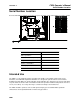
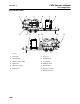
FX50 Operator’s Manual Overview - 4 Unit Components 800-Gallon Tank 1 7 2 8 3 9 4 5 10 11 j36om002w.eps 1. Inlet valve 7. Hose reel 2. Vacuum tank 8. Potholing tools 3. Primary shut-off valve 9. Tool storage 4. Water tank 10. Antifreeze tank 5. Operator’s station 11. Vacuum filter 6. Power unit 12. Cyclonic separator 13.
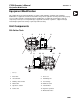
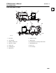
FX50 Operator’s Manual Overview - 5 Unit Components 1200-Gal (4542-L)Tank 1 2 6 3 4 8 7 5 10 9 13 12 11 j36om077w.eps 1. Inlet valve 8. Antifreeze tank 2. Vacuum tank 9. Water tanks 3. Primary shutoff valve 10. Vacuum filter/secondary shutoff valve 4. Operator’s station 11. Drain/Outlet valve 5. Power unit 12. Hose reel 6. Potholing tools 13. Tool storage 7.
FX50 Operator’s Manual Overview - 6 Operator Orientation Operator Orientation 1. Front of unit 3. Rear of unit 2. Right of unit 4. Left of unit Right and left sides of machine are determined by facing towing vehicle. 1 4 2 3 j36om003w.eps About This Manual This manual contains information for the proper use of this machine. See Operation Overview for basic operating procedures. Cross references such as “See page 50” will direct you to detailed procedures.
FX50 Operator’s Manual Foreword - 7 Reporting Safety Defects Foreword This manual is an important part of your equipment. It provides safety information and operation instructions to help you use and maintain your Ditch Witch equipment. Read this manual before using your equipment. Keep it with the equipment at all times for future reference. If you sell your equipment, be sure to give this manual to the new owner. If you need a replacement copy, contact your Ditch Witch dealer.
FX50 Operator’s Manual Foreword - 8 FX50 Operator’s Manual Issue number 1.0/OM-9/12 Part number 053-2545 Copyright 2012 by The Charles Machine Works, Inc. , Ditch Witch, and CMW are registered trademarks of The Charles Machine Works, Inc. U.S. patents pending.
FX50 Operator’s Manual Contents - 9 Contents Overview 1 machine serial number, information about the type of work this machine is designed to perform, basic machine components, and how to use this manual Foreword 7 part number, revision level, and publication date of this manual, and factory contact information Safety 11 machine safety alerts and emergency procedures Controls 21 machine controls, gauges, and indicators and how to use them Operation Overview 37 an overview for completing a jo
Contents - 10 Service Record FX50 Operator’s Manual 131 a record of major service performed on the machine Appendix Information regarding tire safety CMW 133
FX50 Operator’s Manual Safety - 11 Safety Chapter Contents Guidelines . . . . . . . . . . . . . . . . . . . . . . . . . . . . . . . . 12 Safety Alert Classifications . . . . . . . . . . . . . . . . . . 13 Safety Alerts . . . . . . . . . . . . . . . . . . . . . . . . . . . . . . 14 Emergency Procedures . . . . . . . . . . . . . . . . . . . . . 17 • Electric Strike Description . . . . . . . . . . . . . . . . . . . . . . . . . . . . . . . . . . . 17 • If an Electric Line is Damaged . . . . . . . . . . . .
Safety - 12 FX50 Operator’s Manual Guidelines Guidelines Follow these guidelines before operating any jobsite equipment: • Complete proper training and read operator’s manual before using equipment. • Contact your local One-Call (811 in USA) or the One-Call referral number (888-258-0808 in USA and Canada) to have underground utilities located before digging. Also contact any utilities that do not participate in the One-Call service.
FX50 Operator’s Manual Safety - 13 Safety Alert Classifications Safety Alert Classifications These classifications and the icons defined on the following pages work together to alert you to situations which could be harmful to you, jobsite bystanders or your equipment. When you see these words and icons in the book or on the machine, carefully read and follow all instructions. YOUR SAFETY IS AT STAKE. Watch for the three safety alert levels: DANGER, WARNING and CAUTION. Learn what each level means.
FX50 Operator’s Manual Safety - 14 Safety Alerts Safety Alerts Electric shock. Contacting electric lines will cause death or serious injury. Know location of lines and stay away. Confined space will cause suffocation. Use proper procedures for entering or stay away. Vacuum will suffocate. Maintain distance between face and vacuum inlets. Jobsite hazards could cause death or serious injury. Use correct equipment and work methods. Use and maintain proper safety equipment.
FX50 Operator’s Manual Safety - 15 Safety Alerts Improper control function could cause death or serious injury. If control does not work as described in instructions, stop machine and have it serviced. Fire or explosion possible. Fumes could ignite and cause burns. No smoking, no flame, no spark. Moving traffic - hazardous situation. Death or serious injury could result. Avoid moving vehicles, wear high visibility clothing, post appropriate warning signs.
FX50 Operator’s Manual Safety - 16 Safety Alerts Hot pressurized cooling system fluid could cause serious burns. Allow to cool before servicing. Flying objects may cause injury. Wear hard hat and safety glasses. Hot parts may cause burns. Do not touch until cool. Exposure to high noise levels may cause hearing loss. Wear hearing protection. Fall possible. Slips or trips may result in injury. Keep area clean. Battery acid may cause burns. Avoid contact.
FX50 Operator’s Manual Safety - 17 Emergency Procedures Emergency Procedures Jobsite hazards could cause death or serious injury. Use correct equipment and work methods. Use and maintain proper safety equipment. Before operating any equipment, review emergency procedures and check that all safety precautions have been taken. EMERGENCY SHUTDOWN - Turn ignition switch to stop position or push remote engine stop button (if equipped). Electric Strike Description Electric shock.
Safety - 18 FX50 Operator’s Manual Emergency Procedures If an Electric Line is Damaged If you suspect an electric line has been damaged and you are on truck or trailer, DO NOT MOVE. Remain on truck or trailer and take the following actions. The order and degree of action will depend on the situation. • Warn people nearby that an electric strike has occurred. Instruct them to leave the area and contact utility. • Do not allow anyone into area until given permission by utility company.
FX50 Operator’s Manual Safety - 19 Emergency Procedures If a Gas Line is Damaged Fire or explosion possible. Fumes could ignite and cause burns. No smoking, no flame, no spark. Explosion possible. Serious injury or equipment damage could occur. Follow directions carefully. If you suspect a gas line has been damaged, take the following actions. The order and degree of action will depend on the situation. • Immediately shut off engine(s), if this can be done safely and quickly.
Safety - 20 FX50 Operator’s Manual Emergency Procedures If a Fiber Optic Cable is Damaged Do not look into cut ends of fiber optic or unidentified cable. Vision damage can occur. If Machine Catches on Fire Perform emergency shutdown procedure and then take the following actions. The order and degree of action will depend on the situation. • Immediately move battery disconnect switch (if equipped and accessible) to disconnect position.
FX50 Operator’s Manual Controls - 21 Controls Chapter Contents Power Pack . . . . . . . . . . . . . . . . . . . . . . . . . . . . . . . 22 • Controls and Connectors . . . . . . . . . . . . . . . . . . . . . . . . . . . . . . . . . . . 22 • Gauges and Indicators . . . . . . . . . . . . . . . . . . . . . . . . . . . . . . . . . . . . . 25 • Miscellaneous . . . . . . . . . . . . . . . . . . . . . . . . . . . . . . . . . . . . . . . . . . . 28 Tank . . . . . . . . . . . . . . . . . . . . . . . . . . . .
FX50 Operator’s Manual Controls - 22 Power Pack Power Pack Controls and Connectors 2 3 1 4 5 6 j36om016w.eps 1. Hydraulic function switch 4. Water pressure switch 2. Auxiliary outlet switch 5. Ignition switch 3. Throttle 6.
FX50 Operator’s Manual Controls - 23 Power Pack Item Description 1. Hydraulic function switch To direct hydraulic power to the optional boom function, press top. Notes To direct hydraulic power to the door function, move to center position. To direct hydraulic power to the tank tilt function, press bottom. 2. Auxiliary outlet switch To turn on, press top. IMPORTANT: Keep switch in off position unless in use. To turn off, press bottom. c00ic061t.eps 3.
FX50 Operator’s Manual Controls - 24 Power Pack Item Description Notes 5. Ignition switch To start engine, insert key and turn clockwise. IMPORTANT: • When engine is on, blower operates and vacuum is present at tank inlet. • All indicators should light briefly at startup. To stop engine, turn key counterclockwise. 6. Water pressure control To increase water pressure, turn clockwise. To decrease water pressure, turn counterclockwise.
FX50 Operator’s Manual Controls - 25 Power Pack Gauges and Indicators 2 3 1 4 5 6 1. Water pressure gauge 4. Engine oil pressure indicator 2. Fuel gauge 5. Engine oil temperature indicator 3. Hourmeter 6. Cold start wait indicator Item Description 1. Water pressure gauge Displays water pressure when water pressure switch is on and water lance is in use.
FX50 Operator’s Manual Controls - 26 Power Pack Item Description Notes 2. Fuel gauge Displays fuel level in tank. NOTICE: Use low sulfur or ultra low sulfur diesel fuel only. In temperatures below 32° F (0° C), use #1 diesel fuel. Tank holds 19 gal (72 L). 3. Hourmeter Displays engine operating time. Hourmeter runs when ignition switch is on. Use these times to schedule service. 4. Engine oil pressure indicator Indicates engine oil pressure is too low. Engine will stop. 1. Check oil level.
FX50 Operator’s Manual Controls - 27 Power Pack Item Description 5. Cold start wait indicator Indicates intake air preheater is operating. Wait until light goes off before starting engine. See “Cold Start Procedure” on page 57. Notes Explosion possible. Serious injury or equipment damage could occur.
FX50 Operator’s Manual Controls - 28 Power Pack Miscellaneous 2 4 1 3 5 1. Battery disconnect 4. Engine oil drain 2. Flow direction control (optional) 5. Auxiliary outlets 3. Hydraulic fluid drain Item Description Notes 1. Battery disconnect switch To connect, turn clockwise. IMPORTANT: Use battery disconnect switch when servicing, welding, and during long-term storage. To disconnect, turn counterclockwise. _ + c00ic063t.
FX50 Operator’s Manual Controls - 29 Power Pack Item Description Notes 2. Flow direction control To operate in reverse flow mode, turn counterclockwise. Use reverse flow to unload tank contents to another tank. Operate in reverse flow mode only when drain/ outlet valve is open. To operate in vacuum mode, turn clockwise. c00ic605h.eps 3. Hydraulic fluid drain 4. Engine oil drain 5. Auxiliary outlets To drain: • Remove plug. • Replace plug when drain pan is empty. To drain: • Remove plug.
FX50 Operator’s Manual Controls - 30 Tank Tank Tethered Controller 1 UP DOWN 2 j36om018w.eps Item Description Notes 1. Up To raise tank, set hydraulic function switch to the tank position and press UP. Note: The vacuum boom uses a different tethered controller. See page 34. UP To open tank door, set hydraulic function switch to the door position and press UP. c00ic064t.eps 2. Down DOWN c00ic065t.eps CMW To lower tank, set hydraulic function switch to the tank position and press DOWN.
FX50 Operator’s Manual Controls - 31 Tank Machine Controls 2 1 4 6 3 6 5 7 4 8 j36om005w.eps 1. Inlet valve 5. Antifreeze tank supply valve 2. Water tank drain 6. Flow direction control (optional) 3. Water tank supply valve 7. Drain/Outlet valve 4. Vacuum gauge 8. Reverse flow gauge (optional) Item Description 1. Inlet valve To close valve (stop suction), rotate up. Notes To open valve (start suction), rotate down.
FX50 Operator’s Manual Controls - 32 Tank Item Description 2. Water tank drain To drain tank, open valve. Notes Close valve when tank is empty. c00ic604h.eps 3. Water tank supply valve To open valve (send water from the water tank through the pump and water lance), rotate counterclockwise. IMPORTANT: Water tank supply valve or antifreeze supply valve must be open when pump is running or pump will be damaged. To close valve (stop water flow), rotate clockwise. c00ic603h.eps 4.
FX50 Operator’s Manual Controls - 33 Tank Item Description Notes 6. Flow direction control To operate in reverse flow mode, turn counterclockwise. Use reverse flow to unload tank contents to another tank. Operate in reverse flow mode only when drain/ outlet valve is open. To operate in vacuum mode, turn clockwise. c00ic605h.eps 7. Drain/Outlet valve To drain tank, rotate down. To close drain, rotate up. 8. Reverse flow gauge Displays reverse flow pressure.
FX50 Operator’s Manual Controls - 34 Vacuum Boom (optional) Vacuum Boom (optional) 5 4 3 2 1 j35om053h.eps 1. Boom latch 4. Boom retract 2. Boom up 5. Boom extend 3. Boom down Item Description 1. Boom latch Pull cable to open latch and release boom from saddle. Push boom into latch to lock boom into saddle.
FX50 Operator’s Manual Controls - 35 Vacuum Boom (optional) Item Description Notes 2. Boom up To raise boom, set hydraulic function switch to the optional boom position and press UP. NOTICE: Do not use boom to raise or lower objects. To stop movement, release. 3. Boom down To lower boom, set hydraulic function switch to the optional boom position and press UP. NOTICE: Do not use boom to raise or lower objects. To stop movement, release. 4.
Controls - 36 FX50 Operator’s Manual Vacuum Boom (optional) CMW
FX50 Operator’s Manual Operation Overview - 37 Operation Overview Chapter Contents Planning . . . . . . . . . . . . . . . . . . . . . . . . . . . . . . . . . 38 Setting Up at Jobsite . . . . . . . . . . . . . . . . . . . . . . . 38 Vacuuming . . . . . . . . . . . . . . . . . . . . . . . . . . . . . . . 38 Potholing . . . . . . . . . . . . . . . . . . . . . . . . . . . . . . . . 39 Leaving Jobsite . . . . . . . . . . . . . . . . . . . . . . . . . . . 39 Storing Equipment . . . . . . . . . . . . . . . . . .
Operation Overview - 38 FX50 Operator’s Manual Planning Planning 1. Gather information about jobsite (page 42). 2. Inspect jobsite (page 43). 3. Check supplies and prepare equipment (page 45). Setting Up at Jobsite 1. Prepare jobsite (page 44). 2. Position vacuum excavation unit. 3. Leave unit hitched to towing vehicle or properly stabilized. 4. Block trailer wheels. Vacuuming 1. Connect hoses (page 52). 2. Start unit (page 56). 3. Position optional vacuum boom (page 58). 4. Remove debris (page 59). 5.
FX50 Operator’s Manual Operation Overview - 39 Potholing Potholing 1. Connect hoses (page 52). 2. Start unit (page 56). 3. Pothole (page 60). 4. Disconnect hoses (page 71). 5. Drain tank (page 62). Leaving Jobsite 1. Rinse unit and tools (page 71). 2. Stow tools (page 72). Storing Equipment 1. For cold weather storage, antifreeze vacuum excavation unit (page 70). 2. For long-term storage, disconnect battery disconnect switch (page 29).
Operation Overview - 40 FX50 Operator’s Manual Storing Equipment CMW
FX50 Operator’s Manual Prepare - 41 Prepare Chapter Contents Gather Information . . . . . . . . . . . . . . . . . . . . . . . . . 42 • Arrange for Traffic Control . . . . . . . . . . . . . . . . . . . . . . . . . . . . . . . . . . 42 • Prepare for Working Near Existing Utilities . . . . . . . . . . . . . . . . . . . . . 42 • Plan for Emergency Services . . . . . . . . . . . . . . . . . . . . . . . . . . . . . . . . 42 Inspect Jobsite . . . . . . . . . . . . . . . . . . . . . . . . . . . .
Prepare - 42 FX50 Operator’s Manual Gather Information Gather Information A successful job begins before the excavation. The first step in planning is reviewing information already available about the job and jobsite. Arrange for Traffic Control If working near a road or other traffic area, contact local authorities about safety procedures and regulations.
FX50 Operator’s Manual Prepare - 43 Inspect Jobsite Inspect Jobsite • Follow U.S. Department of Labor regulations on excavating and trenching (Part 1926, Subpart P) and other similar regulations. • Contact your local One-Call (811 in USA) or the One-Call referral number (888-258-0808 in USA and Canada) to have underground utilities located before digging. Also contact any utilities that do not participate in the One-Call service..
FX50 Operator’s Manual Prepare - 44 Prepare Jobsite Prepare Jobsite Jobsite hazards could cause death or serious injury. Use correct equipment and work methods. Use and maintain proper safety equipment. To help avoid injury: • If jobsite classification is in question or if the possibility of unmarked electric utilities exists, classify jobsite as electric. • Expose lines by hand before digging. Cutting high voltage cable can cause electrocution.
FX50 Operator’s Manual Prepare - 45 Check Supplies and Prepare Equipment Check Supplies and Prepare Equipment Assemble Accessories Fire Extinguisher If required, mount a fire extinguisher near the power unit but away from possible points of ignition. The fire extinguisher should always be classified for both oil and electric fires. It should meet legal and regulatory requirements. Lighting Kit If you will need additional light, plug lighting kit into provided outlet.
Prepare - 46 FX50 Operator’s Manual Check Supplies and Prepare Equipment Prepare Equipment Fluid Levels • fuel • hydraulic fluid • engine coolant • battery charge • engine oil • blower oil Condition and Function • filters (air, oil, hydraulic) • belts • hydraulic pump • blower • tires • hoses and valves • couplers and fittings • water tanks CMW
FX50 Operator’s Manual Transport - 47 Transport Chapter Contents Lift . . . . . . . . . . . . . . . . . . . . . . . . . . . . . . . . . . . . . . 48 • Points . . . . . . . . . . . . . . . . . . . . . . . . . . . . . . . . . . . . . . . . . . . . . . . . . . 48 • Procedure . . . . . . . . . . . . . . . . . . . . . . . . . . . . . . . . . . . . . . . . . . . . . . . 48 Haul . . . . . . . . . . . . . . . . . . . . . . . . . . . . . . . . . . . . . 49 • Inspect Trailer . . . . . . . . . . . . . . . . . .
FX50 Operator’s Manual Transport - 48 Lift Lift Crushing weight. If load falls or moves it could kill or crush you. Use proper procedures and equipment or stay away. Points Lifting points are identified by lifting decals. Lifting at other points is unsafe and can damage machinery. Procedure Power Pack Use a crane capable of supporting 3000 lb (1360 kg). Use top lift point as shown. Tank Use crane capable of supporting 2500 lb (1134 kg). Use top lift point (1) as shown.
FX50 Operator’s Manual Transport - 49 Haul Haul Crushing weight. If load falls or moves it could kill or crush you. Use proper procedures and equipment or stay away. To help avoid injury: • Do not haul or move trailer unless tank is fully lowered and horizontal. Damage to machine or injury to personnel could occur. • Do not haul or move trailer unless optional vacuum boom is secured by boom latch. Damage to machine or injury to personnel could occur.
FX50 Operator’s Manual Transport - 50 Haul Hitch Trailer 1. Back tow vehicle to trailer. 2. Put manual transmission into first or reverse gear or automatic transmission into park. Turn off ignition. Set parking brake. 3. Connect trailer drawbar, lunette or coupler to tow vehicle hitch and lock in place with lock pin. If needed, adjust drawbar, lunette or coupler height (shown) to level load. 4. Connect safety chains to tow vehicle chain keepers (cross-shaped slots on bumper of tow vehicle).
FX50 Operator’s Manual Vacuum and Pothole - 51 Vacuum and Pothole Chapter Contents Connect Hoses . . . . . . . . . . . . . . . . . . . . . . . . . . . . 52 Determine Tank Fill Level . . . . . . . . . . . . . . . . . . . 53 • 300-gal Vacuum Tank on T9SE6 or T9SH6 Trailer . . . . . . . . . . . . . . . 53 • 800-gal Vacuum Tank on T18S Trailer . . . . . . . . . . . . . . . . . . . . . . . . 54 • 1200-gal Vacuum Tank on T26S Trailer . . . . . . . . . . . . . . . . . . . . . . . 55 Start Unit . . . . . .
FX50 Operator’s Manual Vacuum and Pothole - 52 Connect Hoses Connect Hoses 1. Remove vacuum hoses from storage. 2. If potholing, remove 2-in-1 potholing tool or basic potholing tool from storage. 3. Connect hoses. Secure all locking clamps. 4. Ensure drain/outlet valve is closed. 5. If potholing, connect water pressure hose.
FX50 Operator’s Manual Vacuum and Pothole - 53 Determine Tank Fill Level Determine Tank Fill Level Use these reference charts to help determine how full of various materials the vacuum tank can be without overloading trailer. Exceeding the maximum fill level will overload the trailer. Never exceed the trailer capacity. You can exceed the vacuum tank lifting capacity if you drain the tank down to the lifting capacity before lifting tank.
FX50 Operator’s Manual Vacuum and Pothole - 54 Determine Tank Fill Level 800-gal Vacuum Tank on T18S Trailer Material Maximum Vacuum Tank Fill Level Water tank fill level CMW full (200 gal) full (300 gal) empty (0 gal) wood chips (dry) 100% 100% 100% snow (dry) 100% 100% 100% water 100% 93% 100% light weight mud (8-10 lb/gal) 96% 86% 100% earth (dry, loose) 90% 81% 100% caliche 83% 74% 100% earth, loam 83% 74% 100% medium weight mud (10-12 lb/gal) 79% 70% 95% limesto
FX50 Operator’s Manual Vacuum and Pothole - 55 Determine Tank Fill Level 1200-gal Vacuum Tank on BT26 Trailer Material Maximum Vacuum Tank Fill Level Water tank fill level full (500 gal) empty (0 gal) wood chips (dry) 100% 100% snow (dry) 100% 100% water 94% 100% light weight mud (8-10 lb/gal) 87% 100% earth (dry, loose) 82% 100% caliche 75% 100% earth, loam 75% 100% medium weight mud (10-12 lb/gal) 71% 99% limestone (crushed) 61% 85% asphalt 59% 81% sand (dry) 59% 81%
Vacuum and Pothole - 56 FX50 Operator’s Manual Start Unit Start Unit EMERGENCY SHUTDOWN: Turn ignition switch to STOP. Standard Procedure IMPORTANT: If power pack is not connected to external tank control valves, connect a -04 hose with a minimum working pressure rating of 3000 psi (207 bar) from pressure (1) to power beyond (2) connections on power pack. j36om006w.eps 1. Open tank inlet valve. NOTICE: Avoid idling engine with inlet valve closed. 2.
FX50 Operator’s Manual Vacuum and Pothole - 57 Start Unit Cold Start Procedure Explosion possible. Serious injury or equipment damage could occur. Follow directions carefully. To help avoid injury: do not use ether or starting fluid. 1. Open tank inlet valve. NOTICE: Avoid idling engine with inlet valve closed. 2. If equipped with reverse flow, ensure vacuum is in “vacuum” mode before starting. 3. Insert key. 4. Turn key clockwise to “run” position (key on, engine off). See page 24 for more information.
Vacuum and Pothole - 58 FX50 Operator’s Manual Position Vacuum Boom Position Vacuum Boom The vacuum boom is optional equipment. Contact your Ditch Witch dealer to add this option. Procedure Electric shock. Contacting electric lines will cause death or serious injury. Know location of lines and stay away. Incorrect procedures could result in death, injury, or property damage. Learn to use equipment correctly. To help avoid injury: • Latch boom before tilting tank.
FX50 Operator’s Manual Vacuum and Pothole - 59 Remove Debris Remove Debris EMERGENCY SHUTDOWN: Turn ignition switch to STOP. Procedure 1. Position vacuum hose in area to be excavated. 2. Start engine. Vacuum will suffocate. Maintain distance between face and vacuum inlets. Fire or explosion possible. Do not vacuum flammable or combustible substances. 3. Open inlet valve if necessary to begin excavation. Incorrect procedures could result in death, injury, or property damage.
FX50 Operator’s Manual Vacuum and Pothole - 60 Pothole Pothole EMERGENCY SHUTDOWN: Turn ignition switch to STOP. 1. Start engine. Vacuum will suffocate. Maintain distance between face and vacuum inlets. Fire or explosion possible. Do not vacuum flammable or combustible substances. 2. Open water tank valve. 3. Move water pump switch to on. 4. Open inlet valve if necessary. 5. Position tool over area to be excavated and begin pothole. Electric shock.
FX50 Operator’s Manual Vacuum and Pothole - 61 Pothole 6. Adjust water pressure as needed to match soil conditions and/or material of utility being exposed. Jobsite hazards could cause death or serious injury. Use correct equipment and work methods. Use and maintain proper safety equipment. To help avoid injury: Test water pressure on a sample of the material to be located. Adjust pressure until no damage occurs to the material. High pressure water can cut utility lines. 7.
Vacuum and Pothole - 62 FX50 Operator’s Manual Drain Tank Drain Tank EMERGENCY SHUTDOWN: Turn ignition switch to STOP. 1. Ensure that unit is hitched to vehicle. See “Hitch Trailer” on page 50. 2. Haul unit to approved dumping area. Incorrect procedures could result in death, injury, or property damage. Learn to use equipment correctly. To help avoid injury: • Do not unhitch unit from tow vehicle before or during dumping. A freestanding unit can become unstable when tilting tank.
FX50 Operator’s Manual Vacuum and Pothole - 63 Drain Tank 9. If further draining is necessary, open tank door. See “Open/Close Tank Door” on page 66. Crushing weight could cause death or serious injury. Use proper procedures and equipment or stay away. To help avoid injury: Use tools (provided with unit) if unit must be serviced with tank door up. 10. Tilt tank up. Allow tank to drain completely. 11. Connect water pressure hose to water lance. 12. Turn water pump switch on. Adjust water pressure. 13.
FX50 Operator’s Manual Vacuum and Pothole - 64 Unload to Another Tank Unload to Another Tank Optional reverse flow mode can be used to transfer vacuumed material to another tank or disposal site. Incorrect procedures could result in death, injury, or property damage. Learn to use equipment correctly. To help avoid injury: • Keep unit in “vacuum” mode unless pressure is needed. • Restrain hose prior to pressurization. Unrestrained hose may cause property damage, injury or death.
FX50 Operator’s Manual Vacuum and Pothole - 65 Unload to Another Tank 5. Move valve handle counterclockwise to engage “reverse flow” mode and start engine. Material will flow into offboard tank. 6. Increase throttle as desired to transfer material. 7. When transfer is complete, throttle down completely and turn off engine. Close FX tank drain/outlet valve. 8. Close offboard tank inlet valve and disconnect hose from offboard tank inlet valve. 9. Move handle clockwise to “vacuum” mode and turn on engine.
Vacuum and Pothole - 66 FX50 Operator’s Manual Open/Close Tank Door Open/Close Tank Door Crushing weight could cause death or serious injury. Use proper procedures and equipment or stay away. To help avoid injury: Use tools (provided with unit) if unit must be serviced with tank door up. To help avoid injury: Do not raise tank with door held closed only by vacuum. Door may suddenly open and possibly injure someone. NOTICE: Do not drive with tank or door raised.
FX50 Operator’s Manual Vacuum and Pothole - 67 Open/Close Tank Door 1200 Tank: Open 1. Push door seal control to SEAL. 2. Turn tank door lock counterclockwise. 3. Pull door seal control to RELEASE. 1 4. Turn door handle to DISENGAGE and pull out. 2 5. Push door lift control to OPEN. 6. Ensure door lift latch (1) engages properly. Door lift latch (1) should be fully seated on pin (2). NOTICE: If door latch is not fully seated on pin, door will close and possibly injure someone. om0663h.eps Close 1.
Vacuum and Pothole - 68 FX50 Operator’s Manual Open/Close Tank Door CMW
FX50 Operator’s Manual Complete the Job - 69 Complete the Job Chapter Contents Antifreeze Fluid Excavation Unit . . . . . . . . . . . . . 70 • Add Antifreeze . . . . . . . . . . . . . . . . . . . . . . . . . . . . . . . . . . . . . . . . . . . 70 • Reclaim Antifreeze . . . . . . . . . . . . . . . . . . . . . . . . . . . . . . . . . . . . . . . . 70 Rinse Equipment . . . . . . . . . . . . . . . . . . . . . . . . . . 71 Disconnect . . . . . . . . . . . . . . . . . . . . . . . . . . . . . . .
Complete the Job - 70 FX50 Operator’s Manual Antifreeze Fluid Excavation Unit Antifreeze Fluid Excavation Unit Add Antifreeze Follow these steps for overnight or long-term storage of unit during cold weather. 1. Fill antifreeze tank with a propylene-glycol based antifreeze. 2. Ensure that water tank valve is closed. 3. Open antifreeze tank valve. 4. Connect water pressure hose to water lance. 5. Start engine. 6. Move water pump switch to on. If freshwater tank is empty, move to bypass. 7.
FX50 Operator’s Manual Complete the Job - 71 Rinse Equipment Rinse Equipment Spray water onto equipment to remove dirt and mud. Use water lance. Thoroughly rinse inside of tank and around door seal. Confined space will cause suffocation. Use proper procedures for entering or stay away. To help avoid injury: Enter tank only if necessary. Follow U.S. Department of Labor guidelines for entering confined spaces. NOTICE: Do not spray water onto operator’s console. Electrical components could be damaged.
Complete the Job - 72 FX50 Operator’s Manual Stow Tools Stow Tools Make sure optional vacuum boom, potholing tools, water lance, and other tools are properly stowed.
FX50 Operator’s Manual Service - 73 Service Chapter Contents Precautions . . . . . . . . . . . . . . . . . . . . . . . . . . . . . . 74 Recommended Lubricants/Service Key . . . . . . . 76 Each Use . . . . . . . . . . . . . . . . . . . . . . . . . . . . . . . . . 78 10 Hour . . . . . . . . . . . . . . . . . . . . . . . . . . . . . . . . . . 81 25 Hour . . . . . . . . . . . . . . . . . . . . . . . . . . . . . . . . . . 90 50 Hour . . . . . . . . . . . . . . . . . . . . . . . . . . . . . . . . . .
FX50 Operator’s Manual Service - 74 Precautions Precautions Incorrect procedures could result in death, injury, or property damage. Learn to use equipment correctly. To help avoid injury: • Unless otherwise instructed, all service should be performed with engine off. • Refer to engine manufacturer’s manual for engine maintenance instructions. Working Under Raised Debris Tank Crushing weight could cause death or serious injury. Use proper procedures and equipment or stay away.
FX50 Operator’s Manual Service - 75 Precautions Working Under Raised Tank Door Crushing weight could cause death or serious injury. Use proper procedures and equipment or stay away. To help avoid injury: Use tools (provided with unit) if unit must be serviced with tank door up. 1. Locate door lock tools in tool storage area and bring to rear of tank. 2. Raise tank door completely. 3. Pin door lock tools into place as shown. 4. Lower tank lid until load is supported by door lock tools.
FX50 Operator’s Manual Service - 76 Recommended Lubricants/Service Key Recommended Lubricants/Service Key Item Description DEO Diesel engine oil meeting or exceeding CH-4 per the API service classification or E5 per the European Automobile Manufacturer’s Association (ACEA) and SAE viscosity recommended by engine manufacturer (SAE 15W40) HTG NGLI #2 premium grade, petroleum-based grease with high temperature resistance and good mechanical stability NDO SAE30 non-detergent oil SGL Synthetic gear oi
FX50 Operator’s Manual Service - 77 Recommended Lubricants/Service Key Engine Oil Temperature Chart Temperature range anticipated before next oil change See engine manual for more information about oil viscosity and operation in arctic conditions. Approved Fuel This engine is designed to run on diesel fuel. Use only high quality fuel meeting ASTM D975 No. 2D, EN590, or equivalent. At temperatures below 32° F (0° C) winter fuel blends are acceptable. See the engine operation manual for more information.
FX50 Operator’s Manual Service - 78 Each Use Each Use Location Task Trailer Check torque of hitch bolts Notes Check hydraulic brake actuator bolts If equipped Check hydraulic brake fluid level If equipped; DOT 3 or 4 Check trailer battery Check tire pressure and lug nut torque Check lights and reflectors Trailer Check Torque of Hitch Bolts Check torque of hitch bolts. Torque varies by trailer model. Refer to “Specifications” on page 115. j36om020w.
FX50 Operator’s Manual Service - 79 Each Use Check Hydraulic Brake Fluid Level Check hydraulic brake fluid level at master cylinder each use. Fluid should be visible a top of master cylinder. Add DOT 3 or DOT 4 brake fluid and bleed brakes as needed. See page 107. j36om022w.eps Check Trailer Battery Check battery connections for wear or corrosion. Keep connections clean and tight. Batteries supplied by factory are maintenance-free. Service replacement batteries according to manufacturer’s instructions.
FX50 Operator’s Manual Service - 80 Each Use Check Lights and Reflectors Check lights and reflectors for correct operation and cleanliness. j33om013h.
FX50 Operator’s Manual Service - 81 10 Hour 10 Hour Location Task Vacuum System Check engine oil level Notes Inspect belts (water pump, blower and fan) Check air filter service indicator Check hydraulic fluid level THF Check hydraulic hoses Check blower oil level SGL Check blower Check water pump oil level NDO Check water pump Check water pump regulator Clean water pump filter Clean vacuum air filter Check spray nozzle Drain cyclonic separator canister Debris Tank Check vacuum tank hoses Chec
FX50 Operator’s Manual Service - 82 10 Hour Vacuum System Check Engine Oil Level Check engine oil at dipstick (2) before operation and every 10 hours thereafter. Check with unit on level surface and at least 15 minutes after stopping engine. Add DEO at fill (1) as necessary to keep oil level at highest line on dipstick. 1 2 j36om009w.eps Inspect Belts 1 Check fan (2), blower (1), and water pump (3) belts every 10 hours for damage or wear. 2 3 j36om058w.
FX50 Operator’s Manual Service - 83 10 Hour Check Air Filter Indicator and Clean Dust Trap 1 2 Check air filter indicator (2) and inspect dust trap (1) for cracks every 10 hours. Change filter elements when indicator reaches red zone. NOTICE: Only open the air filter canister when air restriction is indicated. Change the elements, do not attempt to clean them. • Compressed air or water may damage filter elements. • Tapping filter elements to loosen dirt may damage filter seals. j36om007w.
FX50 Operator’s Manual Service - 84 10 Hour Check Hydraulic Hoses Check hoses every 10 hours for wear or damage. Replace as needed. Fluid or air pressure could pierce skin and cause injury or death. Stay away. To help avoid injury: • Before disconnecting a hydraulic line, turn engine off and operate all controls to relieve pressure. Lower, block, or support any raised component with a hoist. Cover connection with heavy cloth and loosen connector nut slightly to relieve residual pressure.
FX50 Operator’s Manual Service - 85 10 Hour Check Blower Oil Level 1 With frame level, check blower oil at sight glass (2) every 10 hours. Add SGL at breather (1) as necessary to maintain oil level at halfway point on sight glass (2). Do not overfill. 2 j36om011w.eps Check Blower Check blower every 10 hours for unusual noise or vibration. If malfunction is detected: 1. Stop engine. 2. Consult blower repair manual. j36om024w.
FX50 Operator’s Manual Service - 86 10 Hour Check Water Pump Check water pump unit every 10 hours for leaks, loose fittings, unusual noise or vibration. Repair if necessary. j36om025w.eps Fluid or air pressure could pierce skin and cause injury or death. Stay away. To help avoid injury: • Before using system, check that all connections are tight and all lines are undamaged. • Use a piece of cardboard or wood, rather than hands, to search for leaks. Fluid leaks can be hard to detect.
FX50 Operator’s Manual Service - 87 10 Hour Check Water Pump Regulator Check for proper operation of regulator every 10 hours. To check: 1. Start engine. 2. Connect water pressure hose to water lance. 3. Move water pressure switch to on. 4. Squeeze water lance handle. Water pump should engage. 5. Release water lance handle. Water pump should disengage. j36om062w.eps If pump does not engage and disengage with movement of water lance handle, water pump control system is not functioning properly.
FX50 Operator’s Manual Service - 88 10 Hour Clean Vacuum Air Filter Clean filter every 10 hours or as needed. To clean filter: 1. Remove filter from canister. 2. Run low pressure water into inside of filter. NOTICE: Do not use high pressure water to clean filter. Filter will be damaged. 3. Allow filter to dry completely before returning to canister. j36om027w.eps Check Spray Nozzle Check spray nozzle every 10 hours. Ensure that water sprays from nozzle in a fan pattern.
FX50 Operator’s Manual Service - 89 10 Hour Debris Tank Check Vacuum Tank Hoses Check hoses every 10 hours for wear or damage. Replace as needed. j36om034w.eps Check Strobe Light Check strobe light for proper function every 10 hours. When ignition is on, strobe light should be flashing. Repair if necessary. j36om035w.eps Check Vacuum Tank Door Seals and Fittings Check door seal every 10 hours for wear or damage. Repair if necessary. Check for leaks and loose fittings every 10 hours.
FX50 Operator’s Manual Service - 90 25 Hour Check Tank Deflector Check tank deflector every 10 hours for buildup, wear, or damage. Clean or replace as needed. j36om037w.eps 25 Hour Location Task Notes Vacuum System Change water pump oil Initial service, NDO Vacuum System Change Water Pump Oil 1 Change oil after the first 25 hours of operation and every 100 hours thereafter. Change oil more frequently if working in dusty conditions. • Drain at drain plug (3) while oil is warm.
FX50 Operator’s Manual Service - 91 50 Hour 50 Hour Location Task Vacuum System Check water pump belt tension Notes Check fan belt tension Check blower belt tension Inspect cooling fan Check blower relief valve Check water pressure hoses Debris Tank Lube tank pivot pins Vacuum Boom Lube boom pivot Boom is optional equipment Vacuum System Check Water Pump Belt Tension Check belt every 10 hours for correct tension, damage or wear. Replace worn belt. Tighten as needed.
FX50 Operator’s Manual Service - 92 50 Hour Check Fan Belt Tension Check fan belt tension every 50 hours. Belt is properly tensioned when it moves about 3/8” (10 mm) when pushed at the long span (shown). Adjust as needed. See “Adjust Fan Belt Tension” on page 102. j36om073w.eps Check Blower Belt Tension Check belt every 10 hours for correct tension, damage or wear. Replace worn belt. Both ends of tube must touch spring caps for belt to be correctly tensioned. Tighten as needed.
FX50 Operator’s Manual Service - 93 50 Hour Check Blower Relief Valve Check relief valve for proper operation every 50 hours. To check: 1. Ensure that vacuum inlet valve and drain valve are both closed. 2. Start engine. Vacuum will start to build. 3. When vacuum goes over relief, check for suction at the bottom of the relief air filter. If suction is not present, stop engine and check relief valve. j36om068w.eps Check Water Pressure Hoses Check hoses every 50 hours for wear or damage. Replace as needed.
FX50 Operator’s Manual Service - 94 50 Hour Debris Tank Lube Tank Pivot Pins Lube two pins every 50 hours with MPG. j36om032w.eps Vacuum Boom Lube Boom Pivot Lube six zerks every 50 hours with MPG. j36om033w.
FX50 Operator’s Manual Service - 95 100 Hour 100 Hour Location Task Notes Vacuum System Change water pump oil NDO Lube blower bearings HTG Debris Tank Check tank mounting bolts Vacuum Boom Check structure Vacuum System Change Water Pump Oil 1 Change oil after the first 25 hours of operation and every 100 hours thereafter. Change oil more frequently if working in dusty conditions. • Drain at drain plug (3) while oil is warm.
FX50 Operator’s Manual Service - 96 250 Hour Debris Tank Check Tank Mounting Bolts Check vacuum tank mounting bolts (shown, on both sides) every 100 hours for looseness and damage. Tighten or replace as needed. Vacuum Boom j36om038w.eps Check Structure Check boom elbow every 100 hours. Replace as needed. 250 Hour Location Task Vacuum System Inspect air intake system Notes Vacuum System Inspect Air Intake System Inspect intake piping for cracked hoses, loose clamps, or punctures.
FX50 Operator’s Manual Service - 97 500 Hour 500 Hour Location Task Notes Vacuum System Change engine oil and filter DEO Change fuel filter and clean filter screen Vacuum System Change Engine Oil and Filter 3 2 4 Change oil and filter every 500 hours. 1. Drain crankcase through drain (1) while oil is warm. 1 2. Replace filter (2) each time oil is changed. 3. Add 8 qt (7.5L) of DEO at fill neck (4). 4. Verify correct oil level at dipstick (3). j36om041w.
FX50 Operator’s Manual Service - 98 1000 Hour 1000 Hour Location Task Notes Vacuum System Change blower oil SGL Change hydraulic fluid THF Vacuum System Change Blower Oil 1 Change oil every 1000 hours. Change oil more frequently if working in dusty conditions. • Drain at drain plug (3) while oil is warm. • Add SGL at breather (1) until oil is at halfway point on sight glass (2). 2 3 j36om064w.eps Change Hydraulic Fluid Drain hydraulic fluid (2) and add (1) THF every 1000 hours.
FX50 Operator’s Manual Service - 99 2000 Hour 2000 Hour Location Task Vacuum System Replace water pump belt Notes Replace blower belt Replace fan belt Vacuum System Replace Water Pump Belt Replace belt every 2000 hours. j36om043w.eps Replace Blower Belt Replace belt every 2000 hours. j36om044w.
FX50 Operator’s Manual Service - 100 2000 Hour Replace Fan Belt Replace belt every 2000 hours. j36om061w.
FX50 Operator’s Manual Service - 101 As Needed As Needed Location Task Vacuum System Clean engine cooling system Notes Change air filter Adjust fan belt tension Adjust water pump belt tension Change water pump filter Adjust blower belt tension Lube blower for longterm storage Change blower relief air filter Empty cyclonic separator canister Debris Tank Trailer Clean primary shutoff valve Clean secondary shutoff valve 1200 Tank Add surge brake fluid DOT 3 or 4 Vacuum System Clean Engine Coolin
FX50 Operator’s Manual Service - 102 As Needed Change Air Filter Change air filter element when red band on filter minder (5) is visible. Push button to reset indicator. 3 2 4 To replace air filter: 5 1. Disengage latches (2) and remove cover (1). 2. Remove the primary (3) and secondary (6) filters from the canister (4). 3. Wipe out the canister (4) and cover (2) with a damp cloth. 4.
FX50 Operator’s Manual Service - 103 As Needed Adjust Water Pump Belt Tension 1. Turn off engine and remove key. 2. Apply moderate thumb pressure to belt between pulleys. 2 1 Belt is properly tensioned when deflection is about .2-.3” (5-8 mm). 3. If needed, loosen four bolts (2) and turn adjustment screw (3) clockwise or counterclockwise until tube (1) touches bracket. 3 4. Tighten four bolts. j36om067w.eps Change Water Pump Filter j35om064h.eps 1. Open filter housing. 2.
FX50 Operator’s Manual Service - 104 As Needed Lube Blower for Long-term Storage Lubricate blower before long-term storage to help prevent rust and lockup. 1. Remove plug from fitting at filter. 2. Start engine. 3. Spray light oil into port and run unit for 1-2 minutes. 4. Turn off engine. j36om072w.eps Change Blower Relief Air Filter Check air filter whenever vacuum gauge goes over 16” (406 mm) of mercury. Change as needed.
FX50 Operator’s Manual Service - 105 As Needed Debris Tank Clean Primary Shutoff Valve Clean primary shutoff valve as needed. Replace primary shutoff valve as needed. 2 1 To clean: 3 1. Open tank door. See “Open/Close Tank Door” on page 66. 2. Spray valve housing inside vacuum tank with high-pressure water. 3. Store water pressure hose. j36om054w.eps 4. Close tank door. See “Open/Close Tank Door” on page 66. To remove: 1. Loosen three wingnuts (1) and pull out valve housing (2). 2. Remove ball (3).
FX50 Operator’s Manual Service - 106 As Needed Clean Secondary Shutoff Valve (1200 Tank) Clean secondary shutoff valve as needed. Replace secondary shutoff valve as needed. To clean: 1. Loosen wingnuts and open water trap door. 1 2. Remove filter canister lid and remove filter element. 2 3. Drain water from element housing. 4. Spray valve housing and rubber seat inside water trap housing with high-pressure water. j36om055w.eps 5. Disconnect water pressure hose and store properly. 6.
FX50 Operator’s Manual Service - 107 As Needed Trailer Add Surge Brake Fluid 1 Add surge brake fluid at cap (1) as needed and bleed brakes. 2 1. Remove lever guide and flat emergency lever spring by removing two 5/16” hex head bolts and lock washers. 2. Using short strokes, pull forward on emergency lever (2) until brake fluid in master cylinder stops bubbling. 3.
FX50 Operator’s Manual Service - 108 200 Mile 200 Mile Location Task Notes Trailer Adjust electric brakes Initial Adjust hydraulic brakes Initial Trailer Adjust Electric Brakes (Initial) Adjust brakes after 200 miles (320 km). 1. Place adequate jack stands under frame rails and remove wheels. 2. Remove cover from adjusting slot on bottom of backing plate. 3. Rotate adjuster starwheel with screwdriver or brake spoon to expand brake shoes. Adjust until drum is very difficult to turn by hand. 4.
FX50 Operator’s Manual Service - 109 200 Mile Adjust Hydraulic Brakes (Initial) Adjust hydraulic brakes after 200 miles (320 km). Crushing weight could cause death or serious injury. Use proper procedures and equipment or stay away. 1. Use a jack and suitable jack stands to raise wheels so that wheels can be rotated by hand. 1 2. Rotate wheel forward by hand to reposition free backing primary brake shoe. 3. Remove adjusting plug from backing plate at wheel. 2 4.
FX50 Operator’s Manual Service - 110 3000 Mile 3000 Mile Location Task Trailer Adjust electric brakes Notes Adjust hydraulic brakes Trailer Adjust Electric Brakes Adjust brakes every 3000 miles (5000 km). 1. Place adequate jack stands under frame rails and remove wheels. 2. Remove cover from adjusting slot on bottom of backing plate. 3. Rotate adjuster starwheel with screwdriver or brake spoon to expand brake shoes. Adjust until drum is very difficult to turn by hand. 4.
FX50 Operator’s Manual Service - 111 3000 Mile Adjust Hydraulic Brakes Adjust hydraulic brakes every 3000 miles (5000 km). Crushing weight could cause death or serious injury. Use proper procedures and equipment or stay away. 1. Use a jack and suitable jack stands to raise wheels so that wheels can be rotated by hand. 1 2. Rotate wheel forward by hand to reposition free backing primary brake shoe. 3. Remove adjusting plug from backing plate at wheel. 2 4.
FX50 Operator’s Manual Service - 112 12,000 Mile 12,000 Mile Location Task Trailer Inspect brake shoes and linings Notes Adjust and lubricate bearings Trailer Inspect Brake Shoes and Linings Inspect shoes and linings every 12 months or 12,000 miles (20 000 km) for wear. When lining is worn to 1/16” (2 mm) or less, replace linings. Replace shoe and lining if contaminated by oil. j36om047w.
FX50 Operator’s Manual Service - 113 12,000 Mile Adjust and Lubricate Bearings 1. Place adequate jack stands under frame rails and remove wheels. 2 2. Unscrew grease cap (11) while holding the hub stationary. 3. Bend locking tang (14) down from outer spindle nut (13) and remove spindle nut (3). 4. Remove tang washer, unscrew inner spindle nut and remove spindle washer (16). 8 9 5. Remove hub from spindle. Do not drop outer bearing cone. 6. Pry seal (2) from hub and remove inner bearing cone (3).
Service - 114 FX50 Operator’s Manual 12,000 Mile CMW
FX50 Operator’s Manual Specifications - 115 300 Specifications 300 L W H j35om028h.eps j36om076w.eps Dimensions U.S. Metric L Length 222 in 5.6 m H Height 92 in 2.3 m W Width 96 in 2.4 m Dry weight 7150 lb 3243 kg Weight with full tanks (water) 10,350 lb 4695 kg Tank U.S. Metric Capacity 300 gal 1136 L Length 66 in 1.7 m Diameter 50 in 1.
Specifications - 116 FX50 Operator’s Manual 300 Engine U.S. Metric Deutz D2011L03i, diesel Cooling medium oil Aspiration: natural Number of cylinnders: 3 Displacement 142 in 3 2.3 L Bore 3.7 in 94 mm Stroke 4.4 in 112 mm Engine manufacturer’s gross power rating (per SAE 1995) 48.7 hp 36.3 kW Rated engine speed 2800 rpm 2800 rpm Hydraulic system U.S.
FX50 Operator’s Manual Specifications - 117 300 Vacuum system U.S. Metric Drive type belt Displacement 1020 cfm 28.8 m3/min Maximum vacuum 16 in Hg 405 mm Hg Vacuum tank door diameter 52 in 1.3 m Drain/outlet valve size 6 in 152 mm Inlet valve size 4 in 102 mm Primary shutoff valve size 12 in 305 mm Filter type washable polyester Filter area 100 ft2 9.3 m2 Suction hose size 4 in 102 mm Suction hose length (total) 30 ft 9.1 m Water pump system U.S.
Specifications - 118 FX50 Operator’s Manual 300 T9SE6/T9SH6 Trailer U.S. Metric Clearance (at jack foot pad) 12 in 305 mm Adj. coupler height 18-24 in 457-610 mm Width between fenders 76 in 1.9 m Width outside fenders 96 in 2.4 m Number of axles 2 Coupler (square mount drawbar) 3 in or 2.5 in Type of brakes electric or hydraulic surge Lug nut torque 95 ft•lb 129 N•m Hitch bolt torque 200 ft•lb 271 N•m Electrical system 12V DC ST235/85R16, E 80 psi 5.
FX50 Operator’s Manual Specifications - 119 800 800 L W H j36om057w.eps Dimensions U.S. Metric L Length 263 in 6.7 m H Height 92 in 2.3 m W Width 100.5 in 2.55 m Dry weight 9045 lb 4103 kg Weight with full tanks (water) 17,135 lb 7772 kg Tank U.S. Metric Capacity 800 gal 3028 L Length 98 in 2.5 m Diameter 50 in 1.
Specifications - 120 FX50 Operator’s Manual 800 Engine U.S. Metric Deutz D2011L03i, diesel Cooling medium oil Aspiration: natural Number of cylinnders: 3 Displacement 142 in 3 2.3 L Bore 3.7 in 94 mm Stroke 4.4 in 112 mm Engine manufacturer’s gross power rating (per SAE 1995) 48.7 hp 36.3 kW Rated engine speed 2800 rpm 2800 rpm Hydraulic system U.S.
FX50 Operator’s Manual Specifications - 121 800 Vacuum system U.S. Metric Drive type belt Displacement 1020 cfm 28.8 m3/min Maximum vacuum 16 in Hg 405 mm Hg Vacuum tank door diameter 52 in 1.3 m Drain/outlet valve size 6 in 152 mm Inlet valve size 4 in 102 mm Primary shutoff valve size 12 in 305 mm Filter type washable polyester Filter area 100 ft2 9.3 m2 Suction hose size 4 in 102 mm Suction hose length (total) 30 ft 9.1 m Water pump system U.S.
Specifications - 122 FX50 Operator’s Manual 800 T18S Trailer U.S. Metric Clearance (at jack foot pad) 12 in 305 mm Adj. coupler height 17-26 in 432-660 mm Width between fenders 80.5 in 2m Width outside fenders 100.5 in 2.6 m Number of axles 2 Coupler (square mount drawbar) 3 in or 2.5 in Type of brakes electric Lug nut torque 300 ft•lb 407 N•m Hitch bolt torque 200 ft•lb 271 N•m Electrical system 12V DC 215/75R-17.5, H16TL 125 psi 8.
FX50 Operator’s Manual Specifications - 123 1200 1200 W L H j36om078w.eps Dimensions U.S. Metric L Length 245 in 6.2 m H Height 99 in 2.5 m W Width 100.5 in 2.55 m Dry weight 11,230 lb 5094 kg Weight with full tanks (water) 24,480 lb 11 104 kg Tank U.S. Metric Capacity 1200 gal 4542 L Length 106 in 2.7 m Diameter 60 in 1.
Specifications - 124 FX50 Operator’s Manual 1200 Engine U.S. Metric Deutz D2011L03i, diesel Cooling medium oil Aspiration: natural Number of cylinnders: 3 Displacement 142 in 3 2.3 L Bore 3.7 in 94 mm Stroke 4.4 in 112 mm Engine manufacturer’s gross power rating (per SAE 1995) 48.7 hp 36.3 kW Rated engine speed 2800 rpm 2800 rpm Hydraulic system U.S.
FX50 Operator’s Manual Specifications - 125 1200 Vacuum system U.S. Metric Drive type belt Displacement 1020 cfm 28.8 m3/min Maximum vacuum 16 in Hg 405 mm Hg Vacuum tank door diameter 62 in 1.6 m Drain/outlet valve size 6 in 152 mm Inlet valve size 4 in 102 mm Primary shutoff valve size 12 in 305 mm Filter type washable polyester Filter area 100 ft2 9.3 m2 Water trap capacity 8 gal 30.3 L Suction hose size 4 in 102 mm Suction hose length (total) 30 ft 9.
Specifications - 126 FX50 Operator’s Manual 1200 T26S Trailer U.S. Metric Clearance (at jack foot pad) 12 in 305 mm Adj. coupler height 18-27 in 457-686 mm Width between fenders 50 in 1.3 m Width outside fenders 100.5 in 2.6 m Number of axles 2 Coupler (square mount drawbar) 3 in or 2.5 in Type of brakes electric Lug nut torque 190-210 ft•lb 258-285 N•m Hitch bolt torque 300 ft•lb 407 N•m Electrical system 12V DC ST235/85R16, F 95 psi 6.
FX50 Operator’s Manual Support - 127 Procedure Support Procedure Notify your dealer immediately of any malfunction or failure of Ditch Witch equipment. Always give model, serial number, and approximate date of your equipment purchase. This information should be recorded and placed on file by the owner at the time of purchase. Return damaged parts to dealer for inspection and warranty consideration if in warranty time frame.
FX50 Operator’s Manual Warranty - 128 Warranty Ditch Witch Equipment and Replacement Parts Limited Warranty Policy Subject to the limitation and exclusions herein, free replacement parts will be provided at any authorized Ditch Witch dealership for any Ditch Witch equipment or parts manufactured by The Charles Machine Works, Inc. (CMW) that fail due to a defect in material or workmanship within one (1) year of first commercial use (Exception: 2 years for all SK5 attachments).
FX50 Operator’s Manual Service Record - 131 Service Record Service Performed Date Hours CMW
Service Record - 132 Service Performed CMW FX50 Operator’s Manual Date Hours
FX50 Operator’s Manual Appendix - 133 Appendix Chapter Contents Tire Safety Information CMW
TIRE SAFETY INFORMATION 1.1. STEPS FOR DETERMINING CORRECT LOAD LIMIT – TRAILER Determining the load limits of a trailer includes more than understanding the load limits of the tires alone. On all trailers there is a Federal certification/VIN label that is located on the forward half of the left (road) side of the unit. This certification/VIN label will indicate the trailer’s Gross Vehicle Weight Rating (GVWR). This is the most the fully loaded trailer can weigh.
The Tire Information Placard is attached adjacent to or near the trailer’s VIN (Certification) label at the left front of the trailer. 1.1.2. TRAILERS OVER 10,000 POUNDS GVWR (NOTE: These trailers are not required to have a tire information placard on the trailer.) 1. Determine the empty weight of your trailer by weighing the trailer using a public scale or other means. This step does not have to be repeated. 2.
Innerliner separation - the parting of the innerliner from cord material in the carcass. Light truck (LT) tire - a tire designated by its manufacturer as primarily intended for use on lightweight trucks or multipurpose passenger vehicles. Load rating - the maximum load that a tire is rated to carry for a given inflation pressure. Maximum load rating - the load rating for a tire at the maximum permissible inflation pressure for that tire.
1.4. TIRE SAFETY - EVERYTHING RIDES ON IT The National Traffic Safety Administration (NHTSA) has published a brochure (DOT HS 809 361) that discusses all aspects of Tire Safety, as required by CFR 575.6. This brochure is reproduced in part below. It can be obtained and downloaded from NHTSA, free of charge, from the following web site: http://www.nhtsa.dot.gov/cars/rules/TireSafety/ridesonit/tires_index.
1.5.2. UNDERSTANDING TIRE PRESSURE AND LOAD LIMITS Tire inflation pressure is the level of air in the tire that provides it with load-carrying capacity and affects the overall performance of the trailer. The tire inflation pressure is a number that indicates the amount of air pressure– measured in pounds per square inch (psi) or kilopascals (kpa) –a tire requires to be properly inflated.
1.5.5. TIRE SIZE To maintain tire safety, purchase new tires that are the same size as the trailer's original tires or another size recommended by the manufacturer. Look at the tire information placard, the owner's manual, or the sidewall of the tire you are replacing to find this information. If you have any doubt about the correct size to choose, consult with your dealer. 1.5.6.
1.5.9.2. Information on Light Truck Tires Please refer to the diagram below. Tires for light trucks have other markings besides those found on the sidewalls of passenger tires. LT - indicates the tire is for light trucks or trailers. ST - indicates the tire is for trailer use only. Max. Load Dual kg (lbs) at kPa (psi) Cold - indicates the maximum load and tire pressure when the tire is used as a dual, that is, when four tires are put on each axle. Max.