FT5 - SERVICE SERIAL NUMBER SERVICE SERIAL NUMBER Record the serial numbers and date of purchase of your equipment in the spaces below.
FT5 - SERVICE SUPPORT PROCEDURE SUPPORT PROCEDURE Notify your dealer immediately of any malfunction or failure of Ditch Witch equipment. Always give model, serial number, and approximate date of your equipment purchase. This information should be recorded and placed on file by the owner at the time of purchase. Return damaged parts to dealer for inspection and warranty consideration if in warranty time frame. Order genuine Ditch Witch replacement or repair parts from your authorized Ditch Witch dealer.
FT5 - FOREWORD RESOURCES FOREWORD This manual is an important part of your equipment. It provides safety information and operation instructions to help you use and maintain your Ditch Witch equipment. Read this manual before using your equipment. Keep it with the equipment at all times for future reference. If you sell your equipment, be sure to give this manual to the new owner. If you need a replacement copy, contact your Ditch Witch dealer.
FT5 - FOREWORD RESOURCES Operator's Manual FT5 Issue No.1.0/OP-3/99 Part Number 054-058 Copyright 1999 by The Charles Machine Works, Inc., Perry, Oklahoma , Ditch Witch, Jet Trac, Pro Tech, Fluid Miser, Perma-Soil, Modularmatic, Roto Witch, AutoCrowd, and Subsite are registered trademarks of The Charles Machine Works, Inc. Pierce Airrow is a registered trademark of Oklahoma Airrow, Inc.
FT5 - CONTENTS RESOURCES CONTENTS SERVICE . . . . . . . . . . . . . . . . . . . . . . . . . . . . . . . . . . . . . . . 1 Serial Number . . . . . . . . . . . . . . . . . . . . . . . . . . . . . . . . 1 Support Procedure . . . . . . . . . . . . . . . . . . . . . . . . . . . . 2 Resources . . . . . . . . . . . . . . . . . . . . . . . . . . . . . . . . . . . 2 FOREWORD . . . . . . . . . . . . . . . . . . . . . . . . . . . . . . . . . . . . 3 CONTROLS . . . . . . . . . . . . . . . . . . . . . . . . . . . .
FT5 - CONTENTS RESOURCES OPERATION . . . . . . . . . . . . . . . . . . . . . . . . . . . . . . . . . . . 21 Mix Drilling Fluid . . . . . . . . . . . . . . . . . . . . . . . . . . . . . 21 Pump Fluid to Boring Unit. . . . . . . . . . . . . . . . . . . . . . 23 Operate in Cold Weather . . . . . . . . . . . . . . . . . . . . . . 24 LUBRICATION AND MAINTENANCE . . . . . . . . . . . . . . . 25 Lubrication . . . . . . . . . . . . . . . . . . . . . . . . . . . . . . . . . 25 Maintenance . . . . . . . . . . . .
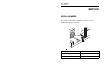
FT5 - CONTROLS 7 OVERVIEW CONTROLS OVERVIEW 1. Filler neck 2. Mixing valve 3. Discharge valve 4. Circulation valve 5. Rope start 6. Throttle 7. Choke 8. Tank discharge valve 9.
FT5 - CONTROLS DESCRIPTIONS DESCRIPTIONS Filler Neck Remove cap to add additives to drilling fluid mixture. Replace cap when finished. Mixing Valve Controls flow from filler neck to pump. Open only when pouring additives into filler neck for mixing. Close when finished. IMPORTANT: Do not open valve unless pump is running. Discharge Valve Controls flow from FT5 to fluid pump on boring unit. Circulation Valve Controls flow from pump to tank. Open to circulate fluid between pump and tank while mixing.
FT5 - CONTROLS 9 Rope Start Cranks engine for starting. Pull to start engine. Throttle Controls engine speed. Increasing engine speed also increases pump flow. Choke Regulates air/fuel mixture in engine. Tank Discharge Valve This valve must be open while unit is running. Open this valve and the drain valve to drain fluid from tank. If drawing water into tank from an external source, open the drain valve and close this valve.
FT5 - CONTROLS
FT5 - SAFETY SAFETY For additional precautions and guidelines, consult boring unit operator’s manual before beginning bore. In addition, follow these guidelines before operating any jobsite equipment: • Do not operate any equipment unless you have completed proper training and read the operator’s manual. • Wear personal protective equipment. • Replace missing or damaged safety shields and safety signs. • Do not operate unit where flammable gas is present. • Use equipment carefully.
FT5 - SAFETY SAFETY ALERT CLASSIFICATIONS SAFETY ALERT CLASSIFICATIONS These classifications and the icons defined on the following pages work together to alert you to situations which could be harmful to you, jobsite bystanders or your equipment. When you see these words and icons in the book or on the machine, carefully read and follow all instructions. YOUR SAFETY IS AT STAKE. Watch for the three safety alert levels: DANGER, WARNING and CAUTION. Learn what each level means.
FT5 - SAFETY SAFETY ALERTS AND NOTICES SAFETY ALERTS AND NOTICES Electric shock. Contacting electric lines will cause death or serious injury. Know location of lines and stay away. Deadly gases. Lack of oxygen or presence of gas will cause sickness or death. Provide ventilation. Fire or explosion possible. Fumes could ignite and cause burns. No smoking, no flame, no spark.
FT5 - SAFETY Improper handling or use of chemicals may result in illness, injury, or equipment damage. Follow instructions on labels and in material safety data sheets (MSDS). Fall possible. Slips or trips may result in injury. Keep area clean. Hot parts may cause burns. Do not touch until cool.
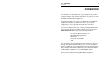
FT5 - LIFT POINTS LIFT Crushing weight could cause death or serious injury. Use proper procedures and equipment or stay away. POINTS Lifting Points Lifting points are identified by lifting decals. Lifting at any other point is unsafe and can damage machinery. PROCEDURE Lifting Skid Lift skid by attaching chains to designated lift points on sides of skid. IMPORTANT: Empty tank before lifting.
FT5 - LIFT PROCEDURE
FT5 - SETUP CHECK EQUIPMENT SETUP CHECK EQUIPMENT Check the following before each day’s work. Refer to LUBRICATION AND MAINTENANCE for additional information and locations. • General appearance of equipment. • Safety sign location and readability. • All guard and shield locations. Replace if missing or worn. • Condition of all wear items such as filters, hoses, and clamps. • Drilling fluid hoses and electric cables for signs of leakage, wear, or other damage. • Engine crankcase oil level.
FT5 - SETUP SELECT DRILLING FLUID SELECT DRILLING FLUID For productive boring and equipment protection, use these recommended Baroid® products, available from your Ditch Witch dealer.
FT5 - SETUP 19 SELECT DRILLING FLUID Bentonite IMPORTANT: Before adding bentonite to drilling fluid, be sure boring unit is equipped to use a bentonite mixture. Bentonite is a dry powder. When properly mixed with water, it cakes on bore walls, lubricating the bore, keeping it open, and holding fluid in the bore. Some things to remember when mixing bentonite: • Use clean water free of salt, calcium, or excessive chlorine. • Use water with a pH level between 7.5 and 10.
FT5 - SETUP PLAN DRILLING FLUID REQUIREMENTS Mixtures Bentonite does not mix well in water containing polymer. To use both, mix bentonite first, then add polymer. Bore-Gel contains premixed bentonite, polymer, and soda ash. Use 15 lb/100 gal (6.8 kg/378.5 L) in normal boring conditions and up to 45 lb/100 gal (20.4 kg/378.5 L) in sand or gravel. PLAN DRILLING FLUID REQUIREMENTS 1. Determine boring conditions and choose appropriate drilling fluid mix. 2.
FT5 - OPERATION MIX DRILLING FLUID OPERATION Jobsite hazards could cause death or serious injury. Use correct equipment and work methods. Use and maintain proper safety equipment. NOTICES: • Wear personal protective equipment including hard hat, safety eye wear, and hearing protection. • Do not wear jewelry or loose clothing. MIX DRILLING FLUID 1. Fill fluid tank with water. Allow room for additives. 2. Open circulation valve and tank discharge valve. 3.
FT5 - OPERATION Measuring Funnel Viscosity Fluid thickness is called viscosity. The higher the viscosity, the harder the fluid is to push through the system. To determine viscosity, you will need a viscosity funnel and a measuring cup, available from your Ditch Witch dealer. 1. Take a fresh sample from the drilling fluid tank. The sample must be more than 1 qt (.95 L). 2. Hold funnel over 1-qt (.95-L) measuring cup and place a finger over the outlet. 3. Pour test sample into top of funnel.
FT5 - OPERATION 23 PUMP FLUID TO BORING UNIT PUMP FLUID TO BORING UNIT Electric shock. Contacting electric lines will cause death or serious injury. Know location of lines and stay away. NOTICE: If electrical strike occurs while fluid hose is connected to boring unit, fluid system also will become electrified. 1. Connect hose from mixing pump to boring unit. 2. Open discharge valve and adjust engine throttle to give desired flow rate to boring unit (approximately half throttle).
FT5 - OPERATION OPERATE IN COLD WEATHER OPERATE IN COLD WEATHER For successful operation in cold weather, follow these procedures. • Use pump to keep drilling fluid circulating at all times, even when traveling to and from the jobsite. • If possible, use all drilling fluid in tank before transporting the unit away from the jobsite. • To prepare unit for storage in cold weather, open all valves and drain tank. Open drain valve on pump and drain pump.
FT5 - LUBRICATION AND MAINTENANCE 25 LUBRICATION LUBRICATION AND MAINTENANCE LUBRICATION Check oil level in engine daily. Fill as needed with SAE 10W40 engine oil. See manufacturer’s manual for lubrication schedule. MAINTENANCE Check filler neck daily. Filler neck should be clean and free of obstructions.
FT5 - LUBRICATION AND MAINTENANCE TROUBLESHOOTING TROUBLESHOOTING Problem Possible solutions poor drilling fluid mix Test water pH and treat if necessary (see characteristics OPERATION for instructions). Residual polymer may be present in tank. Drain tank and remix fluid, adding bentonite first. low yield properties Test water pH. Try a different brand of drilling fluid additive. Add polymer to drilling fluid tank only after bentonite has been yielded out.
FT5 - SPECIFICATIONS TROUBLESHOOTING SPECIFICATIONS Dimensions U.S. Metric L1, length (without hose and valve) 73 in 1.85 m L2, length (with hose and valve) 84 in 2.13 m W, width 32 in 0.81 m H, height 53.5 in 1.36 m Weight with empty fluid tank 402 lb 182 kg Weight with full fluid tank 2071 lb 939 kg Fluid System Fluid tank U.S. 200 gal Fluid Capacities U.S. Metric 757 L Metric Fuel tank 1 gal 3.6 L Engine oil with filter 0.63 qt 0.6 L Engine U.S.
FT5 - SPECIFICATIONS