FM25 Operator’s Manual CMW® Issue 1.
FM25 Operator’s Manual Overview - 1 Overview Chapter Contents Serial Number Location . . . . . . . . . . . . . . . . . . . . . . 2 Intended Use . . . . . . . . . . . . . . . . . . . . . . . . . . . . . . 2 Unit Components . . . . . . . . . . . . . . . . . . . . . . . . . . . 3 About This Manual . . . . . . . . . . . . . . . . . . . . . . . . . . 3 • Bulleted Lists . . . . . . . . . . . . . . . . . . . . . . . . . . . . . . . . . . . . . . . . . . . . . .3 • Numbered Lists . . . . . . . . . . . . . . .
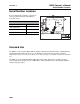
Overview - 2 FM25 Operator’s Manual Serial Number Location Serial Number Location Record serial numbers and date of purchase in spaces provided. Fluid unit serial number is located as shown. Item date of manufacture date of purchase fluid unit serial number engine serial number Intended Use The FM25 is a self-contained drilling fluid unit capable of mixing up to 1000 gal (3785 L) of drilling fluid per tank and transferring fluid under pressure to the drilling unit.
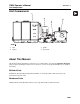
FM25 Operator’s Manual Overview - 3 Unit Components Unit Components 1. tank 3. pumps 2. hopper 4. power unit About This Manual This manual contains information for the proper use of this machine. See the beige Operation Overview pages for basic operating procedures. Cross references such as “See page 50” will direct you to detailed procedures. Bulleted Lists Bulleted lists provide helpful or important information or contain procedures that do not have to be performed in a specific order.
Overview - 4 CMW FM25 Operator’s Manual
FM25 Operator’s Manual Foreword - 5 Foreword This manual is an important part of your equipment. It provides safety information and operation instructions to help you use and maintain your Ditch Witch equipment. Read this manual before using your equipment. Keep it with the equipment at all times for future reference. If you sell your equipment, be sure to give this manual to the new owner. If you need a replacement copy, contact your Ditch Witch dealer.
FM25 Operator’s Manual Foreword - 6 FM25 Operator’s Manual Issue number 1.0/OM-10/07 Part number 053-1187 Copyright 2007 by The Charles Machine Works, Inc. , Ditch Witch, CMW, AutoCrowd, Modularmatic, Jet Trac, Roto Witch, Subsite, Fluid Miser, Perma-Soil, Power Pipe, Super Witch, Super Witch II, Pierce Airrow, The Underground, and The Underground Authority Worldwide are registered trademarks of The Charles Machine Works, Inc. Zahn and InterChange are pending trademarks of The Charles Machine Works, Inc.
FM25 Operator’s Manual Contents - 7 Contents Overview 1 machine serial number, information about the type of work this machine is designed to perform, basic machine components, and how to use this manual Foreword 5 part number, revision level, and publication date of this manual, and factory contact information Safety 9 machine safety alerts and emergency procedures Controls 17 machine controls, gauges, and indicators and how to use them Operation Overview 25 an overview for completing a job
Contents - 8 CMW FM25 Operator’s Manual
FM25 Operator’s Manual Safety - 9 Safety Chapter Contents Guidelines . . . . . . . . . . . . . . . . . . . . . . . . . . . . . . . . 10 Safety Alert Classifications . . . . . . . . . . . . . . . . . . 11 Safety Alerts . . . . . . . . . . . . . . . . . . . . . . . . . . . . . . 12 Emergency Procedures . . . . . . . . . . . . . . . . . . . . . 14 • Electric Strike Description . . . . . . . . . . . . . . . . . . . . . . . . . . . . . . . . . . . .14 • If an Electric Line is Damaged . . . . . . . . . . . .
Safety - 10 FM25 Operator’s Manual Guidelines Guidelines Follow these guidelines before operating any jobsite equipment: • Complete proper training and read operator’s manual before using equipment. • Contact One-Call (888-258-0808) and any utility companies which do not subscribe to One-Call. Have all underground pipes and cables located and marked before operating equipment. If you damage a utility, contact utility company.
FM25 Operator’s Manual Safety - 11 Safety Alert Classifications Safety Alert Classifications These classifications and the icons defined on the following pages work together to alert you to situations which could be harmful to you, jobsite bystanders or your equipment. When you see these words and icons in the book or on the machine, carefully read and follow all instructions. YOUR SAFETY IS AT STAKE. Watch for the three safety alert levels: DANGER, WARNING and CAUTION. Learn what each level means.
FM25 Operator’s Manual Safety - 12 Safety Alerts Safety Alerts Electric shock. Contacting electric lines will cause death or serious injury. Know location of lines and stay away. Deadly gases. Lack of oxygen or presence of gas will cause sickness or death. Provide ventilation. Jobsite hazards could cause death or serious injury. Use correct equipment and work methods. Use and maintain proper safety equipment. Crushing weight could cause death or serious injury.
FM25 Operator’s Manual Safety - 13 Safety Alerts Fire or explosion possible. Fumes could ignite and cause burns. No smoking, no flame, no spark. Moving traffic - hazardous situation. Death or serious injury could result. Avoid moving vehicles, wear high visibility clothing, post appropriate warning signs. Flying objects may cause injury. Wear hard hat and safety glasses. Hot parts may cause burns. Do not touch until cool. Exposure to high noise levels may cause hearing loss. Wear hearing protection.
Safety - 14 FM25 Operator’s Manual Emergency Procedures Emergency Procedures Before operating any equipment, review emergency procedures and check that all safety precautions have been taken. EMERGENCY SHUTDOWN - Turn ignition switch to stop position or push remote engine stop button (if equipped). Electric Strike Description When working near electric cables, remember the following: • Electricity follows all paths to ground, not just path of least resistance.
FM25 Operator’s Manual Safety - 15 Emergency Procedures If an Electric Line is Damaged If you suspect an electric line has been damaged and you are on truck or trailer, DO NOT MOVE. Remain on truck or trailer and take the following actions. The order and degree of action will depend on the situation. • Warn people nearby that an electric strike has occurred. Instruct them to leave the area and contact utility. • Contact utility company to shut off power.
Safety - 16 FM25 Operator’s Manual Emergency Procedures If a Gas Line is Damaged If you suspect a gas line has been damaged, take the following actions. The order and degree of action will depend on the situation. • Immediately shut off engine(s), if this can be done safely and quickly. • Remove any ignition source(s), if this can be done safely and quickly. • Warn others that a gas line has been cut and that they should leave the area. • Leave jobsite as quickly as possible.
FM25 Operator’s Manual Controls - 17 Controls Chapter Contents Power Unit . . . . . . . . . . . . . . . . . . . . . . . . . . . . . . . 18 Mixing Unit . . . . . . . . . . . . . . . . . . . . . . . . . . . . . . .
FM25 Operator’s Manual Controls - 18 Power Unit Power Unit 1. Ignition 7. Glow plug button 2. Fuel gauge 8. Auxiliary outlet 3. Hourmeter 9. Throttle 4. Engine oil pressure indicator 10. Pump 2 control 5. Coolant temperature indicator 11. Pump 1 control 6. Glow plug wait indicator Item Description 1. Ignition To start engine, insert key and turn clockwise. To stop engine, turn key counterclockwise.
FM25 Operator’s Manual Controls - 19 Power Unit Item Description Notes 2. Fuel gauge Displays fuel level in tank. Use #2 diesel fuel. In temperatures below 40° F (4° C), use #1 diesel fuel. Tank holds 9.2 gal (35 L). 3. Hourmeter Displays engine operating time. Hourmeter runs when ignition switch is on. Use these times to schedule service. c00ic259h.eps 4. Engine oil pressure indicator Indicates engine oil pressure is low. Engine will stop. 1. Check oil level.
FM25 Operator’s Manual Controls - 20 Power Unit Item Description 6. Glow plug wait indicator Lights when intake air preheater is operating. Notes Wait until light goes off before starting engine. 7. Glow plug button To activate glow plugs, press. IMPORTANT: Wait until glow plug wait indicator goes off before starting engine. 8. Auxiliary outlet To operate work lights or other 12V devices, plug into outlet. Outlet has power only when ignition switch is on. 9.
FM25 Operator’s Manual Controls - 21 Power Unit Item Description 11. Pump 1 control To turn on pump, press right side of switch. Notes To turn off pump, press left side of switch.
FM25 Operator’s Manual Controls - 22 Item Description Battery disconnect switch To connect, move clockwise. To disconnect, move counterclockwise.
FM25 Operator’s Manual Controls - 23 Mixing Unit Mixing Unit 1. Mixing jet valve 5. Pump drain valve 2. Circulation valve 6. Liquid additive pickup valve 3. Transfer valve 7. Hopper valve 4. Discharge valve 8. Drain plug Item Description 1. Mixing jet valve To allow flow from pump to tank jets, open valve. Notes To stop flow from pump to tank jets, close valve. 2. Circulation valve To circulate fluid while mixing, open valve.
FM25 Operator’s Manual Controls - 24 Mixing Unit Item Description 3. Transfer valve To allow flow from pump to pump, open valve. Notes To stop flow from pump to pump, turn off engine. 4. Discharge valve To allow flow from pump to drilling unit, open valve. To stop flow from pump to drilling unit, close valve. 5. Pump drain valve To drain pump, open valve. To use pump, close valve. 6. Liquid additive pickup valve To allow liquid additives to flow into mixture, open valve.
FM25 Operator’s Manual Operation Overview - 25 Operation Overview Chapter Contents Planning . . . . . . . . . . . . . . . . . . . . . . . . . . . . . . . . . 26 Setting Up at Jobsite . . . . . . . . . . . . . . . . . . . . . . . 26 Mixing Fluid . . . . . . . . . . . . . . . . . . . . . . . . . . . . . . 27 Transferring Fluid . . . . . . . . . . . . . . . . . . . . . . . . . 28 Operating in Cold Weather . . . . . . . . . . . . . . . . . . 28 Leaving Jobsite . . . . . . . . . . . . . . . . . . . . . . . . .
Operation Overview - 26 FM25 Operator’s Manual Planning Planning 1. Gather information about jobsite (page 30). 2. Inspect jobsite (page 30). 3. Check supplies and prepare equipment (page 32). Setting Up at Jobsite 1. Prepare jobsite (page 31). 2. Position fluid unit and connect to drilling unit. See drilling unit operator’s manual. IMPORTANT: Leave unit hitched to towing vehicle or properly stabilized. 3. Block trailer wheels.
FM25 Operator’s Manual Operation Overview - 27 Mixing Fluid Mixing Fluid Jobsite hazards could cause death or serious injury. Use correct equipment and work methods. Use and maintain proper safety equipment. NOTICE: • Wear personal protective equipment including hard hat, safety eye wear, and hearing protection. • Do not wear jewelry or loose clothing. 1. Verify that hopper throat is not plugged before mixing. 2. Fill fluid tank with water. Allow room for additives. 3.
Operation Overview - 28 FM25 Operator’s Manual Transferring Fluid Transferring Fluid Electric shock. Contacting electric lines will cause death or serious injury. Know location of lines and stay away. NOTICE: If electrical strike occurs while fluid hose is connected to drilling unit, fluid system will also become electrified. 1. Connect hose from mixing pump to drilling unit. 2. Open hopper and discharge valves.
FM25 Operator’s Manual Prepare - 29 Prepare Chapter Contents Gather Information . . . . . . . . . . . . . . . . . . . . . . . . . 30 • Arrange for Traffic Control . . . . . . . . . . . . . . . . . . . . . . . . . . . . . . . . . . .30 • Prepare for Working Near Existing Utilities . . . . . . . . . . . . . . . . . . . . . .30 • Plan for Emergency Services . . . . . . . . . . . . . . . . . . . . . . . . . . . . . . . . .30 Inspect Jobsite . . . . . . . . . . . . . . . . . . . . . . . . . . . .
Prepare - 30 FM25 Operator’s Manual Gather Information Gather Information A successful job begins before the excavation. The first step in planning is reviewing information already available about the job and jobsite. Arrange for Traffic Control If working near a road or other traffic area, contact local authorities about safety procedures and regulations.
FM25 Operator’s Manual Prepare - 31 Prepare Jobsite Prepare Jobsite Jobsite hazards could cause death or serious injury. Use correct equipment and work methods. Use and maintain proper safety equipment. NOTICE: • If jobsite classification is in question or if the possibility of unmarked electric utilities exists, classify jobsite as electric. • Cutting high voltage cable can cause electrocution. Expose lines by hand before digging. • All vegetation near operator’s station must be removed.
FM25 Operator’s Manual Prepare - 32 Check Supplies and Prepare Equipment Check Supplies and Prepare Equipment Assemble Accessories Fire Extinguisher If required, mount a fire extinguisher near the power unit but away from possible points of ignition. The fire extinguisher should always be classified for both oil and electric fires. It should meet legal and regulatory requirements.
FM25 Operator’s Manual Transport - 33 Transport Chapter Contents Lift . . . . . . . . . . . . . . . . . . . . . . . . . . . . . . . . . . . . . . 34 • Points . . . . . . . . . . . . . . . . . . . . . . . . . . . . . . . . . . . . . . . . . . . . . . . . . . .34 • Procedure . . . . . . . . . . . . . . . . . . . . . . . . . . . . . . . . . . . . . . . . . . . . . . . .34 Haul . . . . . . . . . . . . . . . . . . . . . . . . . . . . . . . . . . . . .
FM25 Operator’s Manual Transport - 34 Lift Lift Crushing weight. If load falls or moves it could kill or crush you. Use proper procedures and equipment or stay away. Points Lifting points are identified by lifting decals. Lifting at other points is unsafe and can damage machinery. Procedure Tank Use crane capable of supporting the equipment's size and weight. See “Specifications” on page 57 or measure and weigh equipment before lifting.
FM25 Operator’s Manual Transport - 35 Haul Haul IMPORTANT: For trailer information, see the trailer manufacturer’s manual.
Transport - 36 FM25 Operator’s Manual Haul CMW
FM25 Operator’s Manual Drilling Fluid Concepts - 37 Drilling Fluid Concepts Chapter Contents Recommended Products . . . . . . . . . . . . . . . . . . . . 38 Guidelines . . . . . . . . . . . . . . . . . . . . . . . . . . . . . . . . 38 Polymer . . . . . . . . . . . . . . . . . . . . . . . . . . . . . . . . . . 39 Bentonite . . . . . . . . . . . . . . . . . . . . . . . . . . . . . . . . 39 Mixtures . . . . . . . . . . . . . . . . . . . . . . . . . . . . . . . . . 40 • General mixing order . . . . . . . . .
FM25 Operator’s Manual Drilling Fluid Concepts - 38 Recommended Products Recommended Products For productive drilling and equipment protection, use these recommended Baroid® products, available from your Ditch Witch dealer.
FM25 Operator’s Manual Drilling Fluid Concepts - 39 Polymer Polymer This drilling fluid additive provides excellent lubrication and increases viscosity in average soils and heavy clay. In swelling clay, polymer can reduce swelling that traps pipe in the bore. There are two types of polymer: • long chain such as Baroid EZ-Mud • medium chain such as Baroid Quik-Trol Bentonite Bentonite is a dry powder.
FM25 Operator’s Manual Drilling Fluid Concepts - 40 Mixtures Mixtures NOTICE: Bentonite does not mix well in water containing polymer. To use both, mix bentonite first, then add polymer. • If chemicals are added in the wrong order, they will not mix properly and will form clumps. • If tank contains bentonite/polymer mix and more drilling fluid is needed, completely empty tank and start with fresh water before mixing another batch. General mixing order 1. Soda ash 2. Bentonite 3. Polymer 4.
FM25 Operator’s Manual Drilling Fluid Concepts - 41 Mixtures Basic Fluid Recipes Soil type Mixture/100 gal (378 L) of water Notes fine sand 35 lb (16 kg) Bore-Gel coarse sand 35 lb (16 kg) Bore-Gel .5 lb (225 g) No-Sag Add .5 lb (225 g) of Quik-Trol for additional filtrate control fine sand below water table 40 lb (18 kg) Bore-Gel .75 lb (340 g) Quik-Trol Add .5 - 1 gal (2-4 L) of Dinomul in high torque situations coarse sand below water table 40 lb (18 kg) Bore-Gel .75 lb (340 g) Quik-Trol .
Drilling Fluid Concepts - 42 FM25 Operator’s Manual Drilling Fluid Requirements Drilling Fluid Requirements 1. Determine drilling conditions and choose appropriate drilling fluid mix. 2. Estimate amount of supplies needed and check availability. • Drilling fluid • Water supply. If more water than can be carried with the unit will be needed, arrange to transport additional water. • Bentonite and/or polymer 3. Check water quality. • Use meter or pH test strips to test pH of water. If pH is below 9.
FM25 Operator’s Manual Complete the Job - 43 Complete the Job Chapter Contents Rinse Equipment . . . . . . . . . . . . . . . . . . . . . . . . . . 44 Disconnect . . . . . . . . . . . . . . . . . . . . . . . . . . . . . . .
Complete the Job - 44 FM25 Operator’s Manual Rinse Equipment Rinse Equipment Spray water onto equipment to remove dirt and mud. Disconnect Disconnect and store hoses and cables.
FM25 Operator’s Manual Service - 45 Service Chapter Contents Service Precautions . . . . . . . . . . . . . . . . . . . . . . . . 46 • Welding Precaution . . . . . . . . . . . . . . . . . . . . . . . . . . . . . . . . . . . . . . . .46 • Washing Precaution . . . . . . . . . . . . . . . . . . . . . . . . . . . . . . . . . . . . . . . .46 Recommended Lubricants/Service Key . . . . . . . . 47 • Engine Oil Temperature Chart . . . . . . . . . . . . . . . . . . . . . . . . . . . . . . . .
FM25 Operator’s Manual Service - 46 Service Precautions Service Precautions Incorrect procedures could result in death, injury, or property damage. Learn to use equipment correctly. NOTICES: • Unless otherwise instructed, all service should be performed with engine off. • Refer to engine manufacturer’s manual for engine maintenance instructions. Welding Precaution NOTICE: Welding can damage electronics. • Welding currents can damage electronic components.
FM25 Operator’s Manual Service - 47 Recommended Lubricants/Service Key Recommended Lubricants/Service Key Item Description DEO Diesel engine oil meeting or exceeding CH-4 per the API service classification or E5 per the European Automobile Manufacturer’s Association (ACEA) and SAE viscosity recommended by engine manufacturer (SAE 10W30) MPG Multipurpose grease meeting ASTM D217 and NLGI 5 THF Tractor hydraulic fluid, similar to Phillips 66 HG, Mobilfluid 423, Chevron Tractor Hydraulic Fluid, Texaco
FM25 Operator’s Manual Service - 48 Recommended Lubricants/Service Key Engine Oil Temperature Chart Temperature range anticipated before next oil change Approved Coolant Any coolant is approved for use with this unit. However, it was filled with John Deere Cool-Gard coolant before shipment from factory. Add only Cool-Gard (p/n 255-006) or any fully-formulated, ethylene glycol based, low-silicate, heavy-duty diesel engine coolant meeting ASTM specification D5345 (prediluted) or D4985 (concentrate).
FM25 Operator’s Manual Service - 49 10 Hour 10 Hour Location Task Notes Check coolant level DEAC Check engine oil level DEO Check Coolant Level Check coolant level every 10 hours. Add coolant at cap (shown) as needed to maintain level between LOW and FULL on overflow tank. Check Engine Oil Level Check engine oil level at dipstick (1) every 10 hours. Add DEO at fill (2) as needed to maintain oil level at highest line on dipstick.
FM25 Operator’s Manual Service - 50 50 Hour 50 Hour Location Task Notes Check air filter Check battery Change engine oil and filter Lube pump Check radiator Check Air Filter Check air filter every 50 hours. Replace as needed. Check Battery Check battery connections for corrosion every 50 hours. Keep connections clean and tight. Batteries supplied by the factory are maintenance free. Service replacement batteries according to manufacturer’s instructions.
FM25 Operator’s Manual Service - 51 50 Hour Change Engine Oil and Filter (Initial) Change engine oil after 50 hours while oil is warn and with unit parked on level ground. 1. Open drain (3). 2. Replace filter (4). 3. Close drain. 4. Add DEO at fill (2) until oil level is at highest line on dipstick (1). Lube Pump Lube zerk (2) with MPG every 50 hours. Grease cavity is full when grease escapes from grease cylinder relief valve (1).
FM25 Operator’s Manual Service - 52 100 Hour 100 Hour Location Task Change fuel filters Check fan belt tension Change Fuel Filters Change fuel filter (1) and inline fuel filter (2) every 100 hours. 1. Remove filters. 2. Fill new filter with clean fuel. 3. Apply fuel oil over the gasket and hand-tighten. Check Fan Belt Tension Check pump drive belt tension every 100 hours. 1. Turn off engine and remove key. 2. Apply moderate thumb pressure to top of belt.
FM25 Operator’s Manual Service - 53 150 Hour 150 Hour Change Engine Oil and Filter Change engine oil every 150 hours while oil is warn and with unit parked on level ground. 1. Open drain (3). 2. Drain crankcase while oil is warm. 3. Replace filter (4). 4. Close drain. 5. Add DEO at fill (2) until oil level is at highest line on dipstick (1). 250 Hour Change Air Filter Change air filter every 250 hours. 1. Open air filter housing at latches (1). 2. Remove primary (2) and secondary (3) elements. 3.
FM25 Operator’s Manual Service - 54 500 Hour 500 Hour Location Task Replace fan belt Replace pump drive belt Replace Fan Belt Replace fan belt (shown) every 500 hours. To replace 1. Loosen bolts (1, 2) and remove belt. 2. Install new belt and adjust properly. See page 56. Replace Pump Drive Belt Replace pump drive belt (shown) every 500 hours. To replace 1. Loosen three bolts (1, 2; third bolt is on other side of pump mount plate) and remove belt. 2. Install new belt and adjust properly. See page 56.
FM25 Operator’s Manual Service - 55 2000 Hour 2000 Hour Change Engine Coolant Drain cooling system at drain (2). Add approved coolant at fill (1) every two years or 2000 hours. NOTICE: • The use of non-approved coolant may lead to engine damage or premature engine failure and will void engine warranty. • See “Approved Coolant” on page 48. for list of approved coolants.
FM25 Operator’s Manual Service - 56 As Needed As Needed Location Task Adjust fan belt Adjust pump drive belt Adjust Fan Belt Adjust fan belt as needed. 1. Turn off engine and remove key. 2. Apply moderate thumb pressure to belt between pulleys where shown. Belt is properly tensioned when deflection is about 1/4-3/8” (7-9 mm). 3. If needed, loosen alternator bolts (shown) and pull alternator out until correct tension is reached. Adjust Pump Drive Belt Adjust pump drive belt as needed. 1.
FM25 Operator’s Manual Specifications - 57 Specifications Component weights U.S. Metric Pumping/power unit 1150 lb 520 kg Mixing hopper (each) 100 lb 50 kg 500-gal (1892-L) tank and hoses (each) 500 lb 230 kg 500-gal (1892-L) tank and hoses (w/500 gal/1892 L water) 4650 lb 2100 kg 1000-gal (3785-L) tank and hoses (each) 1050 lb 480 kg 1000-gal (3785-L) tank and hoses (w/990 gal/3748 L water) 9250 lb 4200 kg Dimensions with two 1000-gal (3785-L) tanks U.S.
Specifications - 58 FM25 Operator’s Manual Dimensions with two 500-gal (1892-L) tanks (not shown) U.S. Metric L Length, overall 175 in 4.45 m W Width, overall 92 in 2.34 m H Height, without fill pipe 68 in 1.73 m Height, with fill pipe 75 in 1.91 m Weight, dry 2350 lb 1070 kg System weight, with fluid (500 gal/1892 L per tank) 10, 650 lb 4830 kg Performance U.S.
FM25 Operator’s Manual Engine Specifications - 59 U.S. Metric Kubota D1105, diesel Cooling medium water Injection indirect Aspiration natural Number of cylinders 3 Displacement 68.5 in3 1.12 L Bore 3.07 in 78.0 mm Stroke 3.09 in 78.4 mm Manufacturer’s gross power (per SAE J1995) 24.8 hp 18.5 kW Estimated net power rating (per SAE J1349) 21.6 hp 16.1 kW Rated speed 3000 rpm 3000 rpm * Exceeding these operating angles will cause engine damage.
Specifications - 60 FM25 Operator’s Manual Fluid Capacities U.S. Metric Fuel tank 9.2 gal 35 L Engine oil, including filter 4.2 qt 4L Noise levels Operator 88 dBA sound pressure per ISO 6394. Exterior 101 dBA sound power per ISO 6393. Specifications are called out according to SAE recommended practices. Specifications are general and subject to change without notice. If exact measurements are required, equipment should be weighed and measured.
FM25 Operator’s Manual Support - 61 Procedure Support Procedure Notify your dealer immediately of any malfunction or failure of Ditch Witch equipment. Always give model, serial number, and approximate date of your equipment purchase. This information should be recorded and placed on file by the owner at the time of purchase. Return damaged parts to dealer for inspection and warranty consideration if in warranty time frame.
FM25 Operator’s Manual Warranty - 62 Warranty Ditch Witch Equipment and Replacement Parts Limited Warranty Policy Subject to the limitation and exclusions herein, free replacement parts will be provided at any authorized Ditch Witch dealership for any Ditch Witch equipment or parts manufactured by The Charles Machine Works, Inc. (CMW) that fail due to a defect in material or workmanship within one (1) year of first commercial use (Exception: 2 years for all SK attachments).
FM25 Operator’s Manual Service Record - 65 Service Record Service Performed Date Hours CMW
Service Record - 66 Service Performed CMW FM25 Operator’s Manual Date Hours