830R/T Operator’s Manual CMW® Issue 1.
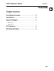
830R/T Operator’s Manual Overview - 1 Overview Chapter Contents Serial Number Location . . . . . . . . . . . . . . . . . . . . . . 2 Intended Use . . . . . . . . . . . . . . . . . . . . . . . . . . . . . . 3 About This Manual . . . . . . . . . . . . . . . . . . . . . . . . . . 3 • Bulleted Lists . . . . . . . . . . . . . . . . . . . . . . . . . . . . . . . . . . . . . . . . . . . . . 3 • Numbered Lists . . . . . . . . . . . . . . . . . . . . . . . . . . . . . . . . . . . . . . . . . . .
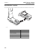
830R/T Operator’s Manual Overview - 2 Serial Number Location Serial Number Location Record serial numbers and date of purchase in spaces provided. Unit serial number is located as shown. e16om014t.
830R/T Operator’s Manual Overview - 3 Intended Use Intended Use The 830R receiver is designed to locate buried pipes and cables at an 83.0775 kHz frequency. Optional passive power and cathodic protection frequencies (60, 120, and 180 Hz in North America; 50, 100, and 150 Hz in other locations) are available. The 830T transmitter places a single 83.0775 kHz signal on a target cable to be detected by an 830R receiver.
Overview - 4 830R/T Operator’s Manual FCC Statement FCC Statement This device complies with Part 15 of the FCC Rules. Operation is subject to the following two conditions: (1) this device may not cause harmful interference, and (2) this device must accept any interference received, including interference that may cause undesired operation. Changes or modifications not expressly approved by The Charles Machine Works, Inc. could void the user’s authority to operate the equipment.
830R/T Manual Foreword - 5 Foreword This manual is an important part of your equipment. It provides safety information and operation instructions to help you use and maintain your Ditch Witch equipment. Read this manual before using your equipment. Keep it with the equipment at all times for future reference. If you sell your equipment, be sure to give this manual to the new owner. If you need a replacement copy, contact your Ditch Witch dealer.
Foreword - 6 830R/T Series Operator’s Manual 830R/T Operator’s Manual Issue number 1.0/OM-12/10 Part number 053-2358 Copyright 2010 by The Charles Machine Works, Inc. , Ditch Witch, CMW, AutoCrowd, Modularmatic, Jet Trac, Roto Witch, Subsite, Fluid Miser, Perma-Soil, Power Pipe, Super Witch, Super Witch II, Pierce Airrow, The Underground, and The Underground Authority Worldwide are registered trademarks of The Charles Machine Works, Inc.
30R/T Operator’s Manual Contents - 7 Contents Overview 1 machine serial number, information about the type of work this machine is designed to perform, basic machine components, and how to use this manual Foreword 5 part number, revision level, and publication date of this manual, and factory contact information Safety 9 machine safety alerts and emergency procedures Controls 15 machine controls and how to use them Locate 27 procedures for locating active, passive and beacon signals Locati
Contents - 8 CMW 830R/T Operator’s Manual
830R/T Operator’s Manual Safety - 9 Safety Chapter Contents Guidelines . . . . . . . . . . . . . . . . . . . . . . . . . . . . . . . . 10 Safety Alert Classifications . . . . . . . . . . . . . . . . . . 11 Safety Alerts . . . . . . . . . . . . . . . . . . . . . . . . . . . . . .
Safety - 10 830R/T Operator’s Manual Guidelines Guidelines Follow these guidelines before operating any jobsite equipment: • Complete proper training and read operator’s manual before using equipment. • Contact your local One-Call (811 in USA) or the One-Call referral number (888-258-0808 in USA and Canada) to have underground utilities located before working. Also contact any utilities that do not participate in the One-Call service.
830R/T Operator’s Manual Safety - 11 Safety Alert Classifications Safety Alert Classifications These classifications and the icons defined on the following pages work together to alert you to situations which could be harmful to you, jobsite bystanders or your equipment. When you see these words and icons in the book or on the unit, carefully read and follow all instructions. YOUR SAFETY IS AT STAKE. Watch for the three safety alert levels: DANGER, WARNING and CAUTION. Learn what each level means.
830R/T Operator’s Manual Safety - 12 Safety Alerts Safety Alerts Electric shock. Contacting electric lines will cause death or serious injury. Know location of lines and stay away. Jobsite hazards could cause death or serious injury. Use correct equipment and work methods. Use and maintain proper safety equipment. Explosion possible. Serious injury or equipment damage could occur. Follow directions carefully. Incorrect procedures could result in death, injury, or property damage.
830R/T Operator’s Manual Safety - 13 Safety Alert Safety Alert Read and follow all safety precautions. Do not operate equipment unless you have completed proper training and have read the operator’s manual. Check that equipment is in good condition and that test leads are clean and have no cracked insulation. HIGH VOLTAGE. This device produces electric current that could cause death or serious injury. Electric shock may result if you touch the clips on the HV output cable.
Safety - 14 830R/T Operator’s Manual Safety Alert CMW
830R/T Operator’s Manual Controls - 15 Controls Chapter Contents 830R Receiver . . . . . . . . . . . . . . . . . . . . . . . . . . . . 16 • Controls . . . . . . . . . . . . . . . . . . . . . . . . . . . . . . . . . . . . . . . . . . . . . . . . 16 • Display . . . . . . . . . . . . . . . . . . . . . . . . . . . . . . . . . . . . . . . . . . . . . . . . . 20 • Menu . . . . . . . . . . . . . . . . . . . . . . . . . . . . . . . . . . . . . . . . . . . . . . . . . . 22 830T Transmitter . . . . . . . . .
830R/T Operator’s Manual Controls - 16 830R Receiver 830R Receiver Controls 999 1 4 2 3 e16om002t.eps 1. Up arrow 3. Depth/Peak Verify/Down arrow 2. Menu/Frequency 4. On/Off/Volume Item Description 1. Up Arrow To scroll up in menu, press. To increase gain in optional power mode, press. c00ic089t.
830R/T Operator’s Manual Controls - 17 830R Receiver Item Description 2. Menu/Frequency To enter menu, press and hold. Notes To select a menu option, press. c00ic090t.eps 3. Depth/Peak Verify/ Down Arrow To change operating frequency (if optional power frequencies are installed), press. See “Menu” on page 22. To estimate depth of properly located signal source, press. To enter peak verify mode, press and hold. To scroll down in menu, press. c00ic091t.eps 4.
830R/T Operator’s Manual Controls - 18 830R Receiver Display - Active (Left/Right) Mode 1 7 6 999 2 3 4 5 e16om001t.eps 1. Signal strength 5. Volume level 2. Left/Right indicator 6. Gain indicator 3. Battery level 7. Signal strength indicator 4. Frequency indicator Item Description 1. Signal Strength Numerically displays the signal strength. 2. Left/Right Arrow Indicates the direction and relative distance to the line.
830R/T Operator’s Manual Controls - 19 830R Receiver Item Description 3. Battery Level Indicates battery level. c00ic093t.eps 4. Frequency Indicator • Three segments indicates full battery power. • One segment indicates low power. • No segments and flashing outline indicates that batteries should be changed immediately. Notes Indicates unit is in active 83k (left/right) locating mode. See “Mode” on page 37. Indicates volume level. IMPORTANT: Lower volume to conserve battery life. 6.
830R/T Operator’s Manual Controls - 20 830R Receiver Display - Power Mode 1 6 99 5 2 3 60 4 e16om005t.eps 1. Signal strength 4. Volume indicator 2. Battery indicator 5. Gain indicator 3. Frequency indicator 6. Signal strength indicator Item Description Notes 1. Signal Strength Numerically displays the signal strength. Range is 0-99. 2. Battery Level Indicates battery level. c00ic093t.eps CMW • Three segments indicates full battery power. • One segment indicates low power.
830R/T Operator’s Manual Controls - 21 830R Receiver Item Description Notes 3. Frequency Indicator Indicates frequency when unit is locating in optional power (single peak) mode. See “Mode” on page 37. Indicates volume level. IMPORTANT: Lower volume to conserve battery life. 5. Gain Indicator Graphically indicates gain level. IMPORTANT: Gain increases to the right. 6. Signal Strength Indicator Graphically indicates the signal strength level. 60 c00ic105t.eps 4. Volume Level si0004h-d.
Controls - 22 830R/T Operator’s Manual 830R Receiver Menu • Press and hold Menu key to enter menu. • Use Up Arrow and Down Arrow keys to cycle through menu options. Press Menu key to select. • Press On/Off key from menu screen to return to locating screen. Units Cycle through depth measurement units with Up Arrow and Down Arrow keys. Press Menu key to select units and return to locating screen. Press On/Off key to return to the menu screen. c00ic106t.
830R/T Operator’s Manual Controls - 23 830T Transmitter 830T Transmitter Controls 1 2 e16om003t.eps 1. Power level 2. On/Off Item Description Notes 1. Power Level To cycle through power levels, press. See “Frequency” on page 39. c00ic099t.eps 2. On/Off To turn on, press. To turn off, press and hold. c00ic092t.
830R/T Operator’s Manual Controls - 24 830T Transmitter Display 1 3 2 e16om004t.eps 1. Mode 3. Battery level 2. Power level Item Description Notes 1. Mode Displays connection mode. See “Transmitter” on page 38. c00ic102t.eps 2. Power Level c00ic101t.eps CMW Displays selected power level.
830R/T Operator’s Manual Item Description 3. Battery Level Indicates battery level. • Filled battery indicates sufficient power. • Flashing battery outline indicates it is time to change batteries. Controls - 25 Notes c00ic100t.
Controls - 26 CMW 830R/T Operator’s Manual
830R/T Operator’s Manual Locate - 27 Locate Chapter Contents Active . . . . . . . . . . . . . . . . . . . . . . . . . . . . . . . . . . . 28 • Setup. . . . . . . . . . . . . . . . . . . . . . . . . . . . . . . . . . . . . . . . . . . . . . . . . . . 28 • Technique . . . . . . . . . . . . . . . . . . . . . . . . . . . . . . . . . . . . . . . . . . . . . . . 30 • Special Situations . . . . . . . . . . . . . . . . . . . . . . . . . . . . . . . . . . . . . . . . . 31 Passive . . . . . . . . . . . . . .
830R/T Operator’s Manual Locate - 28 Active Location Active Location Setup Follow setup procedures for the type of locating you will be doing: direct connection, inductive clamp, or induction (broadcast). For all types of active location that require leads, connect leads at connector. Keep connector covered when not in use. Direct Connection Jobsite hazards could cause death or serious injury. Use correct equipment and work methods. Use and maintain proper safety equipment.
830R/T Operator’s Manual Locate - 29 Active Location Inductive Clamp Jobsite hazards could cause death or serious injury. Use correct equipment and work methods. Use and maintain proper safety equipment. NOTICE: Electric shock or equipment damage can result if transmitter is connected to live cable. Contact qualified utility personnel and follow all standards and requirements for disconnecting and grounding cables. To set up transmitter for use with inductive clamp: 1 1.
830R/T Operator’s Manual Locate - 30 Active Location Technique m 5 7. 5 ft 2 e16om011t.eps IMPORTANT: Follow steps 1-3 for all types of active location. For reference, the illustration above shows direct connection method. If using induction (broadcast), ensure that transmitter handle is in line with and above suspected cable, as shown on previous page. 1. Walk in an arc approximately 25’ (7.5 m) around transmitter. 2. Hold the receiver so that the handle points toward the transmitter, as shown. 3.
830R/T Operator’s Manual Locate - 31 Active Location Mark the Cable Sweep, focus, and trace all detected signals in the area. Mark cable paths with colored paint or flags. See the chart below for standard color markings for cable locations. Utility Color Marking Symbol electric red -E- gas/oil yellow -G- communications orange -TEL- or -TV- water blue -W- sewer green -S- Special Situations Situation What to try Signal is lost. Walk in a circle to detect a tee or bend in the cable.
830R/T Operator’s Manual Locate - 32 Passive Location Passive Location Setup Follow setup procedures for the type of locating you will be doing. Always check receiver battery level at startup. NOTICE: Cables with no A/C current flowing through them are hard to detect and may be hazardous because they may still have voltage potential. To locate, turn on an appliance to cause current to flow and use active search methods.
830R/T Operator’s Manual Locate - 33 Passive Location Focus the Signal Move receiver over detected signal and rotate to find best signal response. Best signal indicates cable direction. Trace the Cable Walk along the suspected path while moving the receiver from side to side across the area. IMPORTANT: Keep receiver handle parallel to the suspected cable path. ss1080a-d.eps Mark the Cable Sweep, focus, and trace all detected signals in the area. Mark cable paths with colored paint or flags.
Locate - 34 830R/T Operator’s Manual Passive Location CMW
830R/T Operator’s Manual Locating Concepts - 35 Locating Concepts Chapter Contents Signal Type . . . . . . . . . . . . . . . . . . . . . . . . . . . . . . . 36 • Active . . . . . . . . . . . . . . . . . . . . . . . . . . . . . . . . . . . . . . . . . . . . . . . . . . 36 • Passive . . . . . . . . . . . . . . . . . . . . . . . . . . . . . . . . . . . . . . . . . . . . . . . . . 36 Recommended Settings . . . . . . . . . . . . . . . . . . . . 36 Mode . . . . . . . . . . . . . . . . . . . . . . . . . . .
830R/T Operator’s Manual Locating Concepts - 36 Signal Type Signal Type The 830R can detect two types of signals: • Active signals that are placed on a target cable with a transmitter. • Passive signals that reside on the target cable. Active There are three ways to place active signals on a target cable with a transmitter: • Direct connection (preferred method) requires a connection to be made directly onto target cable.
830R/T Operator’s Manual Locating Concepts - 37 Mode Mode Receiver The 830R receiver has two available modes. Mode Description Left/Right Allows receiver to trace cables that have had an 83.0775 kHz signal placed on them by a transmitter. Notes si0009c-d.eps Power Allows receiver to trace live power cables. 60 c00ic105t.eps IMPORTANT: Current must be flowing through the cable. In North America, available frequencies are: 60, 120, and 180 Hz.
830R/T Operator’s Manual Locating Concepts - 38 Mode Transmitter The 830T receiver has two operating modes and two troubleshooting indicators. Operating Mode Description Induction (broadcast) Signal is broadcast onto target line using antenna. Notes c00ic102t.eps Direct Connect or Inductive Clamp Signal is placed on target line through direct connect leads or inductive clamps. Indicates a closed circuit with good current flowing in the line. c00ic103t.
830R/T Operator’s Manual Locating Concepts - 39 Receiver Gain Level Receiver Gain Level In left/right mode, the receiver uses automatic gain control and requires no user adjustment. In optional power mode, the user adjusts the receiver gain setting. Action Result Effect increasing gain more sensitive to signal allows location farther away from signal source decreasing gain less sensitive to signal stabilizes signal Frequency The 830R/T system operates at a single active frequency: 83.0775 kHz.
830R/T Operator’s Manual Locating Concepts - 40 Common Signal Problems Common Signal Problems IMPORTANT: If target depth and location are critical, confirm by hand-digging or vacuum excavation. Distortion Distortion often happens when a metallic object partially distorts the signal, or a signal from a parallel cable interferes with target signal. False Signals False signals describe situations where the receiver indicates a cable location where there is no cable.
830R/T Operator’s Manual Locating Concepts - 41 Common Signal Problems Parallel Cables (Diverging Arrows in Left/Right Mode) A B C e16om019t.eps In situations where another cable (C) runs parallel to the target cable (A), the high frequency signal will couple to the other cable. This will allow the user to locate both cables in left/right mode and will create a false cable (B) between them. When locating the false cable, note that the arrows will not indicate the correct direction to the false cable.
Locating Concepts - 42 830R/T Operator’s Manual Common Signal Problems CMW
830R/T Operator’s Manual Service - 43 Service Chapter Contents General Care . . . . . . . . . . . . . . . . . . . . . . . . . . . . . . 44 As Needed . . . . . . . . . . . . . . . . . . . . . . . . . . . . . . .
830R/T Operator’s Manual Service - 44 General Care General Care Under normal operating conditions, receiver and transmitter need only minor maintenance. Following these care instructions can ensure longer equipment life: • Do not drop the equipment. • Do not expose the equipment to high heat (such as in the rear window of a vehicle). • Clean equipment with a damp cloth and mild soap. Never use scouring powder. • Do not immerse in any liquid. • Inspect housing daily for cracks or other damage.
830R/T Operator’s Manual Service - 45 As Needed Transmitter Unit Change Batteries Use six D-cell alkaline batteries in transmitter. 1. Turn quarter turn fastener to open battery cover. 2. Remove batteries. 3. Insert batteries as shown. 4. Close battery door and tighten quarter turn fastener. 5. Check operation. • • A battery error message will be displayed and unit will shut down if a battery is installed backwards. e16om013t.eps Unit will not come on if all batteries are installed backwards.
Service - 46 830R/T Operator’s Manual As Needed CMW
830R/T Operator’s Manual Specifications - 47 830R Receiver Specifications 830R Receiver L W H e16om006t.eps Dimensions U.S. Metric H Height 30.8” 78.1 cm L Length 12.1 ” 30.7 cm W Width 8.4” 21.3 cm Operating weight 5.1 lb 2.3 kg Performance Active frequency: 83.
Specifications - 48 830R/T Operator’s Manual 830R Receiver Environmental U.S. Metric -4°F to 122°F -20°C to 50°C IP rating: IP65 Operating temperature range Regulatory Compliance FCC, IC, CE Features Graphical LCD with white LED backlight Distance sensitive left/right indication Dual tone left/right audio Peak Verify Auto depth reading * Locators are calibrated to these tolerances under ideal test conditions.
830R/T Operator’s Manual Specifications - 49 830T Transmitter 830T Transmitter L W H e16om007t.eps Dimensions U.S. Metric H Height 5.6” 14.2 cm L Length 11.1” 28.2 cm W Width 8.5” 21.6 cm Operating weight 4.6 lb 201 kg U.S. Metric -4°F to 122°F -20°C to 50°C Performance Output frequency: 83.
Specifications - 50 830R/T Operator’s Manual 830T Transmitter CMW
830R/T Operator’s Manual Support - 51 Procedure Support Procedure Notify your dealer immediately of any malfunction or failure of Ditch Witch equipment. Always give model, serial number, and approximate date of your equipment purchase. This information should be recorded and placed on file by the owner at the time of purchase. Return damaged unit to dealer for inspection and warranty consideration if in warranty time frame.
830R/T Operator’s Manual Warranty - 52 Limited Product Warranty Policy Warranty Limited Product Warranty Policy Warranty Periods New Product A twelve-month period starts on the date of delivery to the end user: trackers, remote displays, receivers, transmitters, radars, fault finders A six-month period starts on the date of delivery to the end user: directional and locate beacons A three-month period starts on the date of delivery to the end user: accessories: cables, clamps, canoes, bags, and adapters U
830R/T Operator’s Manual Warranty - 53 Limited Product Warranty Policy Details and Exclusions • The warranty includes only Ditch Witch Electronics products and accessories that are manufactured and distributed by Ditch Witch Electronics. The warranty compensates on defects in material or workmanship. • Defects will be determined through inspection by Ditch Witch Electronics or authorized repair centers.
Warranty - 54 830R/T Operator’s Manual Limited Product Warranty Policy CMW