410SX Gas Operator’s Manual CMW® Issue 2.
410sx Operator’s Manual Overview - 1 Overview Chapter Contents Serial Number Location . . . . . . . . . . . . . . . . . . . . . . 2 Intended Use . . . . . . . . . . . . . . . . . . . . . . . . . . . . . . . 3 Unit Components . . . . . . . . . . . . . . . . . . . . . . . . . . . 4 • Tractor. . . . . . . . . . . . . . . . . . . . . . . . . . . . . . . . . . . . . . . . . . . . . . . . . . . 4 • Plow . . . . . . . . . . . . . . . . . . . . . . . . . . . . . . . . . . . . . . . . . . . . . . . . . . . .
410sx Operator’s Manual Overview - 2 Serial Number Location Serial Number Location Record serial numbers and date of purchase in the spaces provided.
10sx Operator’s Manual Overview - 3 Intended Use Intended Use The 410sx is an articulating, hydrostatic, four-wheel drive, pedestrian vibratory plow designed to bury cable or pipe in a variety of soils. An optional trenching attachment, drilling attachment, and reel carrier are available. The 410sx is powered by a liquid-cooled 49.6 hp (37.0 kW) four-cylinder Kubota gasoline engine. The unit is designed for operation in temperatures typically experienced in excavation and construction work environments.
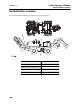
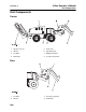
Overview - 4 410sx Operator’s Manual Unit Components Unit Components Tractor 1. Operator console 5. Frame lock 2. Vibrator 6. Articulation joint 3. Feed tube 7. Drilling attachment 4. Plow blade 8. Trencher attachment Plow 1. Feed tube 3. Sod cutter (optional) 2. Vibrator 4.
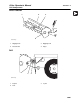
410sx Operator’s Manual Overview - 5 Unit Components H400 Trencher 1 2 3 4 t39om043w.eps 1. Digging chain 3. Digging boom 2. Restraint bar 4. Auger Drill 1 2 3 t39om044w.eps 1. Coupler 3. U-joint 2.
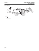
Overview - 6 410sx Operator’s Manual Unit Components Reel Carrier 1.
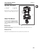
410sx Operator’s Manual Overview - 7 Operator Orientation Operator Orientation 1. Front of unit 3. Rear of unit 2. Left of unit 4. Right of unit Right and left sides of machine are determined by facing front of unit while standing at the controls. About This Manual This manual contains information for the proper use of this machine. See Operation Overview for basic operating procedures. Cross references such as “See page 50” will direct you to detailed procedures.
Overview - 8 410sx Operator’s Manual About This Manual CMW
410sx Operator’s Manual Foreword - 9 Foreword This manual is an important part of your equipment. It provides safety information and operation instructions to help you use and maintain your Ditch Witch equipment. Read this manual before using your equipment. Keep it with the equipment at all times for future reference. If you sell your equipment, be sure to give this manual to the new owner. If you need a replacement copy, contact your Ditch Witch dealer.
410sx Operator’s Manual Foreword - 10 410sx Gas Operator’s Manual Issue number 2.2/OM-01/14 Part number 053-2678 Copyright 2013 by The Charles Machine Works, Inc. , Ditch Witch, CMW, and Roto Witch are registered trademarks of The Charles Machine Works, Inc. U.S. patent pending.
410sx Operator’s Manual Contents - 11 Contents Overview 1 machine serial number, information about the type of work this machine is designed to perform, basic machine components, and how to use this manual Foreword 9 part number, revision level, and publication date of this manual, and factory contact information Safety 11 machine safety alerts and emergency procedures Controls 25 machine controls, gauges, and indicators and how to use them Operation Overview 33 an overview for completing a
Contents - 12 410sx Operator’s Manual Complete the Job 79 procedures for backfilling and restoring the jobsite and rinsing and storing equipment Service 81 service intervals and instructions for this machine including lubrication, replacement of wear items, and basic maintenance Specifications 119 machine specifications including weights, measurements, power ratings, and fluid capacities Support 125 the warranty policy for this machine, and procedures for obtaining warranty consideration and tr
JT100 Operator’s Manual Safety - 11 Safety Chapter Contents Guidelines . . . . . . . . . . . . . . . . . . . . . . . . . . . . . . . . 12 Emergency Procedures . . . . . . . . . . . . . . . . . . . . . 13 • Electric Strike Description . . . . . . . . . . . . . . . . . . . . . . . . . . . . . . . . . . . 13 • If an Electric Line is Damaged . . . . . . . . . . . . . . . . . . . . . . . . . . . . . . . 14 • If a Gas Line is Damaged . . . . . . . . . . . . . . . . . . . . . . . . . . . . . . . . . . .
Safety - 12 JT100 Operator’s Manual Guidelines Guidelines Follow these guidelines before operating any jobsite equipment: • Complete proper training and read operator’s manual before using equipment. • Contact your local One-Call (811 in USA) or the One-Call referral number (888-258-0808 in USA and Canada) to have underground utilities located before digging. Also contact any utilities that do not participate in the One-Call service.
JT100 Operator’s Manual Safety - 13 Emergency Procedures Emergency Procedures Jobsite hazards could cause death or serious injury. Use correct equipment and work methods. Use and maintain proper safety equipment. Before operating any equipment, review emergency procedures and check that all safety precautions have been taken. EMERGENCY SHUTDOWN - Turn ignition switch to stop position or push remote engine stop button (if equipped). Electric Strike Description Electric shock.
Safety - 14 JT100 Operator’s Manual Emergency Procedures If an Electric Line is Damaged If you suspect an electric line has been damaged and you are on drilling unit or bonded equipment, DO NOT MOVE. Remain on drilling machine and take the following actions. The order and degree of action will depend on the situation. • Warn people nearby that an electric strike has occurred. • Have someone contact electric company. • Reverse drilling direction and try to break contact.
JT100 Operator’s Manual Safety - 15 Emergency Procedures If a Gas Line is Damaged Fire or explosion possible. Fumes could ignite and cause burns. No smoking, no flame, no spark. Explosion possible. Serious injury or equipment damage could occur. Follow directions carefully. If you suspect a gas line has been damaged, take the following actions. The order and degree of action will depend on the situation. • Immediately shut off engine(s), if this can be done safely and quickly.
Safety - 16 JT100 Operator’s Manual Emergency Procedures If a Fiber Optic Cable is Damaged Do not look into cut ends of fiber optic or unidentified cable. Vision damage can occur. If Machine Catches on Fire Perform emergency shutdown procedure and then take the following actions. The order and degree of action will depend on the situation. • Immediately move battery disconnect switch (if equipped and accessible) to disconnect position.
410sx Operator’s Manual Safety - 19 Safety Alert Classifications Safety Alert Classifications These classifications and the icons defined on the following pages work together to alert you to situations which could be harmful to you, jobsite bystanders or your equipment. When you see these words and icons in the book or on the machine, carefully read and follow all instructions. YOUR SAFETY IS AT STAKE. Watch for the three safety alert levels: DANGER, WARNING and CAUTION. Learn what each level means.
410sx Operator’s Manual Safety - 20 Machine Safety Alerts Machine Safety Alerts Read operator’s manual. Know how to use all 1 2 3 CMW® controls before operating machine. When you see this sign on the machine or in the manual, read it and use caution. Your safety is at stake. Jobsite hazards could cause death or serious injury. Use correct equipment and work methods. Use and maintain proper safety equipment. Fire or explosion possible. Fumes could ignite and cause burns.
410sx Operator’s Manual Safety - 21 Machine Safety Alerts Fire or explosion possible. Shut engine off before 4 5 fueling. Crushing weight could cause death or serious injury. Use proper procedures and equipment or stay away. Moving parts could cut off hand or foot. Stay away. 6 Tiedown location. See Transport chapter for more information. 7 Lift point. See Transport chapter for more information. 8 Turning shaft will kill you or crush arm or leg. Stay 9 10 away. Explosion possible.
Safety - 22 410sx Operator’s Manual Trencher Trencher H400 1 CMW® Moving digging teeth will cause death or serious injury. Trench cave-in can cause you to fall. Stay away.
410sx Operator’s Manual Safety - 23 Drilling Attachment Drilling Attachment RWIII/RWIV Turning shaft will kill you or crush arm or leg. Stay 1 away.
Safety - 24 410sx Operator’s Manual Drilling Attachment CMW®
410sx Operator’s Manual Controls - 25 Controls Chapter Contents Tractor . . . . . . . . . . . . . . . . . . . . . . . . . . . . . . . . . . . 26 Attachment . . . . . . . . . . . . . . . . . . . . . . . . . . . . . . .
410sx Operator’s Manual Controls - 26 Tractor Tractor 2 3 4 5 6 1 9 8 7 10 11 12 t39om001w.eps 1. Alarm speaker 7. Parking brake 2. Operator presence switch 8. Throttle control 3. Hydraulic fluid temperature indicator 9. Ground drive speed/direction control 4. Check engine / Malfunction indicator light (MIL) 10. Fuel gauge 5. Engine information display 11. Fuel shutoff valves 6. Ignition switch 12. Frame lock Item Description 1.
410sx Operator’s Manual Controls - 27 Tractor Item Description Notes 2. Operator presence switch Detects when operator is present. If switch is released during operation, alram will sound and engine will die. Press and hold switch before moving ground drive control or digging controls out of neutral. 3. Hydraulic fluid temperature indicator 4. Check engine / Malfunction indicator light Lights if hydraulic fluid overheats.
410sx Operator’s Manual Controls - 28 Tractor Item Description Notes 6. Ignition switch To start engine, insert key and turn clockwise. IMPORTANT: If engine does not start on first attempt, check that all interlock requirements have been met, return switch to STOP, and try again. To stop engine, turn counter clockwise. 7. Parking brake (orange) To engage the parking brake, push. To disengage the parking brake, pull. 8. Throttle To increase engine speed, turn clockwise.
410sx Operator’s Manual Controls - 29 Tractor Item Description Notes 10. Fuel gauge Displays fuel level in tank. Use only approved gasoline fuel. Fuel tank holds 8.5 gal (32.2 L). GAS c00ic040w.eps 11. Fuel shutoff valves Opens and closes fuel line between tank and engine. Located under tank on right side. Valve on the right shuts off fuel return. Valve on the left shuts off fuel supply. 12. Frame lock (yellow) Prevents articulation joint from moving during transport or maintenance.
410sx Operator’s Manual Controls - 30 Attachment Controls Attachment Controls 1. Digging chain control (optional) 4. Plow lift/lower control 2. Drill control (optional) 5. Trencher lift/lower control (optional) 3. Plow vibrator control 6. Plow swing lock Item Description Notes 1. Digging chain control To start digging chain, push. Optional, for use with H400 trenching attachment. To reverse digging chain, pull. To stop digging chain, return to neutral position. c00ic003a.
410sx Operator’s Manual Controls - 31 Attachment Controls Item Description Notes 2. Drill direction control To rotate drill string clockwise, push. Optional, for use with Roto Witch drilling attachment. To rotate drill string counter clockwise, pull. c00ic007a.eps 3. Plow vibrator control To start, push. To stop, move to neutral position. 4. Trencher lift control To lower, push. Optional, for use with H400 trenching attachment. To raise, pull. 5. Plow lift control To lower, push.
410sx Operator’s Manual Controls - 32 Attachment Controls Item Description 6. Plow swing lock (blue) To engage plow swing lock, move control toward tractor. To disengage, move control toward plow.
410sx Operator’s Manual Operation Overview - 33 Operation Overview Chapter Contents Planning. . . . . . . . . . . . . . . . . . . . . . . . . . . . . . . . . . 34 Plowing . . . . . . . . . . . . . . . . . . . . . . . . . . . . . . . . . . 34 Trenching. . . . . . . . . . . . . . . . . . . . . . . . . . . . . . . . . 34 Drilling . . . . . . . . . . . . . . . . . . . . . . . . . . . . . . . . . . . 35 Leaving Jobsite. . . . . . . . . . . . . . . . . . . . . . . . . . . .
Operation Overview - 34 410sx Operator’s Manual Planning Planning 1. Gather information about jobsite. See page 38. 2. Inspect jobsite. See page 39. 3. Classify jobsite. See page 40. 4. Select plow blade for your installation. See page 75 5. Select chain and teeth to match your soil type, if necessary. See page 76. 6. Check supplies and prepare equipment. See page 42. 7. Haul equipment to jobsite. See page 50. Plowing 1. Start unit. See page 44. 2. Position tractor and controls. See page 57. 3.
410sx Operator’s Manual Operation Overview - 35 Drilling Drilling 1. Start unit. See page 44. 2. Dig approach trench and target trench. See page 67. 3. Assemble drill string and position tractor. See page 67. 4. Begin drilling. See page 69. 5. Use drill string guide as needed. See page 70. 6. Add rod. See page 71. 7. Backream. See page 71. 8. Shut down tractor. See page 45. 9. Disassemble joints. See page 72. Leaving Jobsite 1. Restore jobsite. See page 80. 2. Rinse equipment. See page 80. 3.
Operation Overview - 36 410sx Operator’s Manual Leaving Jobsite CMW
410sx Operator’s Manual Prepare - 37 Prepare Chapter Contents Gather Information . . . . . . . . . . . . . . . . . . . . . . . . . 38 • Review Job Plan . . . . . . . . . . . . . . . . . . . . . . . . . . . . . . . . . . . . . . . . . . 38 • Notify One-Call Services . . . . . . . . . . . . . . . . . . . . . . . . . . . . . . . . . . . . 38 • Arrange for Traffic Control. . . . . . . . . . . . . . . . . . . . . . . . . . . . . . . . . . . 38 • Plan for Emergency Services . . . . . . . . . . . . . . .
Prepare - 38 410sx Operator’s Manual Gather Information Gather Information A successful job begins before you dig. The first step in planning is reviewing information already available about the job and jobsite. Review Job Plan Review blueprints or other plans. Check for information about existing or planned structures, elevations, or proposed work that may be taking place at the same time.
410sx Operator’s Manual Prepare - 39 Inspect Site Inspect Site Inspect jobsite before transporting equipment. Check for the following: • changes in elevation such as hills or other open trenches • obstacles such as buildings, railroad crossings, or streams • signs of utilities (See “Inspect Jobsite” on page 40.) • traffic • access • soil type and condition Identify Hazards Identify safety hazards and classify jobsite. See “Classify Jobsite” on page 40.
Prepare - 40 410sx Operator’s Manual Classify Jobsite Classify Jobsite Inspect Jobsite • Follow U.S. Department of Labor regulations on excavating and trenching (Part 1926, Subpart P) and other similar regulations. • Contact your local One-Call (811 in USA) or the One-Call referral number (888-258-0808 in USA and Canada) to have underground utilities located before digging. Also contact any utilities that do not participate in the One-Call service.
410sx Operator’s Manual Prepare - 41 Classify Jobsite Apply Precautions Once classified, precautions appropriate for jobsite must be taken. Electric Jobsite Precautions Use one or both of these methods. • Expose line by careful hand digging or soft excavation. • Have service shut down while work is in progress. Have electric company test lines before returning them to service.
Prepare - 42 410sx Operator’s Manual Check Supplies and Prepare Equipment Check Supplies and Prepare Equipment Supplies • fuel • keys • personal protective equipment, such as hard hat and safety glasses Fluid Levels • fuel • hydraulic fluid • battery charge • engine oil Condition and Function • digging chain and teeth • fan belts • light bulbs • filters (air, oil, hydraulic) • tires • pumps and motors • hoses and valves • signs, guards, and shields Accessories Fire Extinguish
410sx Operator’s Manual Drive - 43 Drive Chapter Contents Start Unit . . . . . . . . . . . . . . . . . . . . . . . . . . . . . . . . . 44 Drive . . . . . . . . . . . . . . . . . . . . . . . . . . . . . . . . . . . . . 45 Shut Down . . . . . . . . . . . . . . . . . . . . . . . . . . . . . . . .
410sx Operator’s Manual Drive - 44 Start Unit Start Unit Before operating tractor, read engine manufacturer’s starting and operating instructions. Follow instructions for new engine break-in. Runaway possible. Machine could run over you or others. Learn how to use all controls. Start and operate only from operator’s position. Read operator’s manual. Know how to use all controls before operating machine. When you see this sign on the machine or in the manual, read it and use caution.
410sx Operator’s Manual Drive - 45 Shut Down Drive Tipover possible. Machine can tip over and crush you. To help avoid injury: • Always operate so that operator is on uphill side of machine. • Keep digging boom low when operating or transporting on a slope. • Never jerk control levers. Use a steady even motion. • Drive slowly and cautiously at all times. EMERGENCY SHUTDOWN: Turn ignition switch to STOP. 1. Raise attachments for ground clearance. Ensure that plow swing lock is engaged. 2.
Drive - 46 410sx Operator’s Manual Shut Down CMW
410sx Operator’s Manual Transport - 47 Transport Chapter Contents Lift . . . . . . . . . . . . . . . . . . . . . . . . . . . . . . . . . . . . . . 48 • Points . . . . . . . . . . . . . . . . . . . . . . . . . . . . . . . . . . . . . . . . . . . . . . . . . . 48 • Procedure . . . . . . . . . . . . . . . . . . . . . . . . . . . . . . . . . . . . . . . . . . . . . . . 48 Haul . . . . . . . . . . . . . . . . . . . . . . . . . . . . . . . . . . . . . 50 Tie Down . . . . . . . . . . . . . . . . . . . . . .
410sx Operator’s Manual Transport - 48 Lift Lift Crushing weight. If load falls or moves it could kill or crush you. Use proper procedures and equipment or stay away. Points Lifting points are identified by lifting decals. Lifting at other points is unsafe and can damage machinery. Procedure Tractor Use a crane capable of supporting the equipment's size and weight. See “410sx” on page 119. • Engage frame lock. See page 26. • Use indicated lift points.
410sx Operator’s Manual Transport - 49 Lift H400 Trencher Use crane capable of supporting the equipment's size and weight. See page 119 or measure and weigh equipment before lifting. NOTICE: Do not lift tractor with attachments installed. t39om047w.eps Reel Carrier Use crane capable of supporting the equipment's size and weight. See page 119 or measure and weigh equipment before lifting. NOTICE: Do not lift tractor with attachments installed. t39om048w.
410sx Operator’s Manual Transport - 50 Haul Haul Load Crushing weight. If load falls or moves it could kill or crush you. Use proper procedures and equipment or stay away. To help avoid injury: • Load unit with engine in low idle and boom as low as possible. • Load trailer on level ground. • Load trailer correctly to avoid trailer swaying. • Attach trailer to vehicle before loading or unloading. • If loading onto a tilt-bed trailer, ensure that tilt latch is secured in the correct position.
410sx Operator’s Manual Transport - 51 Tie Down Tie Down Points Tie-down points are identified by tie-down decals. Securing to trailer at other points is unsafe and can damage machinery. Procedure Attach chains at front and rear tie-down points. Make sure chains are tight before transporting unit.
410sx Operator’s Manual Transport - 52 Tie Down Unload Crushing weight. If load falls or moves it could kill or crush you. Use proper procedures and equipment or stay away. To help avoid injury: • Unload unit with engine in low idle and boom as low as possible. • Unload trailer on level ground. • Attach trailer to vehicle before loading or unloading. • If trailer tilts, ensure that tilt latch is secured in the correct position. 1. Lower trailer or ramps. 2. Remove chains from tiedowns. 3.
410sx Operator’s Manual Transport - 53 Tow Tow Under normal conditions, tractor should not be towed. If tractor becomes disabled and towing is necessary: • Open hydrostat bypass valve. • Do not tow for more than 200 yd (180 m). • Tow at less than 1-2 mph (1.5-3.0 km/h). • Unit cannot be steered as it is towed. • Use maximum towing force of 1.5 times unit weight. Procedure 1. Attach tow line to all available tie-down points facing towing vehicle. 2.
Transport - 54 410sx Operator’s Manual Tow CMW
410sx Operator’s Manual Plow - 55 Plow Chapter Contents Setup . . . . . . . . . . . . . . . . . . . . . . . . . . . . . . . . . . . . 56 • Position Tractor . . . . . . . . . . . . . . . . . . . . . . . . . . . . . . . . . . . . . . . . . . . 57 • Attach Product. . . . . . . . . . . . . . . . . . . . . . . . . . . . . . . . . . . . . . . . . . . . 57 Operation . . . . . . . . . . . . . . . . . . . . . . . . . . . . . . . . .
410sx Operator’s Manual Plow - 56 Setup Setup EMERGENCY SHUTDOWN - Turn ignition switch to STOP. Crushing weight could cause death or serious injury. Use proper procedures and equipment or stay away. To help avoid injury: Keep everyone at least 6’ (2 m) from machine, attachments, and their range of movement. Jobsite hazards could cause death or serious injury. Use correct equipment and work methods. Use and maintain proper safety equipment.
410sx Operator’s Manual Plow - 57 Setup Position Tractor 1. Start tractor. See page 44 for start-up procedures. 2. Drive to starting point. Move in line with planned path. See page 45 for operating procedures. 3. Engage parking brake. 4. Lower plow blade to starting point of path. 5. Turn ignition switch to STOP. Attach Product To Pull Product 1. Insert material into pulling grip. 2. Tape grip with duct tape. To Feed Product 1. Remove cable guide. 2. Feed cable through tube from top to bottom. 3.
410sx Operator’s Manual Plow - 58 Operation Operation Crushing weight could cause death or serious injury. Use proper procedures and equipment or stay away. Electrical shock. Contacting electrical lines will cause death or serious injury. Know location of lines and stay away. To help avoid injury: Expose lines by hand before digging. Cutting high voltage cable can cause electrocution Read operator’s manual. Know how to use all controls before operating machine. When you see this sign caution.
410sx Operator’s Manual Plow - 59 Operation Start Plowing Tipover possible. Machine can tip over and crush you. To help avoid injury: • Always operate so that operator is on uphill side of machine. • Keep digging boom low when operating or transporting on a slope. • Never jerk control levers. Use a steady even motion. • Drive slowly and cautiously at all times. 1. Start unit. (See “Start Unit” on page 44.) 2. Adjust throttle to low idle. 3. Check that ground drive control is in neutral. 4.
Plow - 60 410sx Operator’s Manual Operation Finish Plowing 1. When installation is complete, move ground drive control to the neutral position. 2. With vibrator running, lower throttle speed and raise plow to just below ground level. 3. Move plow vibrator control to OFF. NOTICE: Do not operate vibrator when plow is out of the ground. This will cause excessive vibration and will cause rapid wear, and possible damage to the unit and product being installed. 4. Engage plow swing lock. 5.
410sx Operator’s Manual Trench - 61 Trench Chapter Contents Setup . . . . . . . . . . . . . . . . . . . . . . . . . . . . . . . . . . . . 62 Operation . . . . . . . . . . . . . . . . . . . . . . . . . . . . . . . . .
410sx Operator’s Manual Trench - 62 Setup Setup EMERGENCY SHUTDOWN - Release button on operator presense handle and turn ignition switch to OFF position. Crushing weight could cause death or serious injury. Use proper procedures and equipment or stay away. To help avoid injury: Use attachments or counterweights to make front and rear loads balance when all attachments are raised. Contact your Ditch Witch dealer about counterweighting for your equipment.
410sx Operator’s Manual Trench - 63 Operation Operation Breathing crystalline silica dust may cause lung disease. Cutting, drilling, or working materials such as concrete, sand, or rock containing quartz may result in exposure to silica dust. Use dust control methods or appropriate breathing protection when exposed to silica dust. Electrical shock. Contacting electrical lines will cause death or serious injury. Know location of lines and stay away.
Trench - 64 410sx Operator’s Manual Operation Begin Trenching 1. If necessary, adjust throttle to low idle. 2. Move the digging chain control to the ON position. DIGGING CHAIN WILL MOVE. 3. Increase engine speed to full throttle. 4. Slowly lower digging boom to depth. 5. Release parking brake. NOTICE: Machine moves in reverse during trenching. 6. Move ground drive control to desired speed. 7. Lower boom to trench depth and push ground drive control forward to desired trenching speed.
410sx Operator’s Manual Drill - 65 Drill Chapter Contents Prepare Jobsite and Equipment . . . . . . . . . . . . . . 67 • Approach Trench. . . . . . . . . . . . . . . . . . . . . . . . . . . . . . . . . . . . . . . . . . 67 • Target Trench . . . . . . . . . . . . . . . . . . . . . . . . . . . . . . . . . . . . . . . . . . . . 67 • Drill Rod and Equipment . . . . . . . . . . . . . . . . . . . . . . . . . . . . . . . . . . . . 68 Drill . . . . . . . . . . . . . . . . . . . . . . . . . . . . . . . . . .
410sx Operator’s Manual Drill - 66 Drilling Attachment Drilling Attachment Turning shaft will kill you or crush arm or leg. Stay away. To help avoid injury: • Do not straddle trench or drill pipe while drilling. Keep everybody at least 10’ (3 m) away from drill pipe during operation. • Keep all persons away from material being installed. If swivel malfunctions, material being installed can rotate. • Use a guide to align drill rod when starting a bore.
410sx Operator’s Manual Drill - 67 Prepare Jobsite and Equipment Prepare Jobsite and Equipment Approach Trench (1) 1. Mark path where you intend to drill. 2. Dig an approach trench (1) along the intended bore path. IMPORTANT: The approach trench should be at least: • deep enough for pipe to lay flat and enter soil at correct angle • 20’ (6 m) long • 4” (100 mm) wide Target Trench (2) 1. Select a completion point for the drilling project. 2.
Drill - 68 410sx Operator’s Manual Prepare Jobsite and Equipment Drill Rod and Equipment 1. Assemble at least 20’ (6 m), but not more than 30’ (9 m), of drill rod. NOTICE: More than 10-15’ (3-4.5 m) of drill rod out of the trench increases the tendency of drill rod to bend. 2. Install drill bit. 3. Put drill string in approach trench. 4. Move tractor to the approach trench and align the drilling attachment with the intended bore path. 5. Turn off engine. 6. Attach drill string to drilling attachment.
410sx Operator’s Manual Drill - 69 Drill Drill EMERGENCY SHUTDOWN: Release drilling control and turn ignition switch to OFF. 1. Move throttle control to low idle. 2. Start tractor’s engine. 3. Move lever forward to begin clockwise rotation. (See page 31 for attachment control information.) 4. Slowly advance tractor while maintaining clockwise rotation. NOTICE: • Drilling too quickly causes bit to drift off course and may bend drill rod. After bore path is established, speed may be slightly increased.
410sx Operator’s Manual Drill - 70 Drill Using Drill String Guide Turning shaft will kill you or crush arm or leg. Stay away. To help avoid injury: • Do not straddle trench or drill rod while drilling. Keep everybody at least 10’ (3 m) away from drill rod during operation. • Use a drill string guide to align drill rod when starting a bore. Guides are available from your Ditch Witch dealership. Use drill string guide to align drill string as it enters the soil.
410sx Operator’s Manual Drill - 71 Add Rod Add Rod IMPORTANT: Use a helper to add drill rod. 1. Use control to stop drilling attachment. 2. Use ground drive controls to back up unit 6” (150 mm) to loosen drill rod in ground. 3. Disconnect drill rod from drilling attachment. 4. Use ground drive controls to move unit away from bore. 5. Add one drill rod to continue bore.
Drill - 72 410sx Operator’s Manual Disassemble Joints Disassemble Joints 1. Press tab through hole in female side of joint (1) using special tool or screwdriver. 2. Pull rods apart (2).
410sx Operator’s Manual Systems and Equipment - 73 Systems and Equipment Optional Equipment . . . . . . . . . . . . . . . . . . . . . . . . 74 Plow Blades. . . . . . . . . . . . . . . . . . . . . . . . . . . . . . . 75 Chain, Teeth, and Sprockets . . . . . . . . . . . . . . . . . 76 Chain and Tooth Maintenance. . . . . . . . . . . . . . . . 76 Chain Types. . . . . . . . . . . . . . . . . . . . . . . . . . . . . . . 76 Chain Selection . . . . . . . . . . . . . . . . . . . . . . . . . . . .
Systems and Equipment - 74 410sx Operator’s Manual Optional Equipment Optional Equipment See your Ditch Witch dealer for more information about the following optional equipment. 410sx Tractor Equipment Description plow blades and pulling grips Choose the most efficient plow blade for your job based on your desired cover depth range, feed chute diameter, and feed chute radius, as well as your desired speed for straight plowing.
410sx Operator’s Manual Systems and Equipment - 75 Optional Equipment Plow Blades Blade Maintenance • Keep cable guide wing bolts tight. Loose cable guide bolts will break due to plow vibration. • Keep plow feed tube free of rock and debris so that material pulls freely though tube. • Use a speed blade only for straight or gently curving installations. Do not use speed blades for installations that require sharp turns. • Use the plow blade most appropriate for the type of material being installed.
410sx Operator’s Manual Systems and Equipment - 76 Optional Equipment Chain, Teeth, and Sprockets Chain and Tooth Maintenance • Always replace sprockets at the same time you replace the digging chain. Sprockets and chain are designed to work together. Replacing one without the other will cause premature wear of the new part. • Do not use worn teeth. Using dull, worn teeth will decrease production and increase shock load to other trencher components.
410sx Operator’s Manual Systems and Equipment - 77 Optional Equipment Chain Selection These charts are meant as a guideline only. No one chain type works well in all conditions. See your Ditch Witch dealer for soil conditions and chain recommendations for your area. Ask for the latest Chain, Teeth, and Sprockets Parts Catalog.
410sx Operator’s Manual Systems and Equipment - 78 Engine Diagnostic Codes Engine Diagnostic Codes This unit is equipped with a self-diagnostic computer-controlled fuel management system. A variety of sensors send input data to an ECU (Electronic Control Unit) that compares inputs with pre-programed parameters and sends output voltage to a variety of actuators to adjust and operate the engine within specified parameters.
410sx Operator’s Manual Complete the Job - 79 Complete the Job Chapter Contents Restore Jobsite . . . . . . . . . . . . . . . . . . . . . . . . . . . . 80 Rinse Equipment . . . . . . . . . . . . . . . . . . . . . . . . . . 80 Stow Tools . . . . . . . . . . . . . . . . . . . . . . . . . . . . . . .
Complete the Job - 80 410sx Operator’s Manual Restore Jobsite Restore Jobsite After product is installed, return spoils to the trench. Rinse Equipment Spray water onto equipment to remove dirt and mud. NOTICE: Do not spray water onto operator’s console. Electrical components could be damaged. Wipe down instead. Stow Tools Make sure all tools and accessories are loaded and properly secured on trailer.
410sx Operator’s Manual Service - 81 Service Chapter Contents Service Precautions . . . . . . . . . . . . . . . . . . . . . . . . 82 Recommended Lubricants/Service Key . . . . . . . 83 • Engine Oil Selection Chart . . . . . . . . . . . . . . . . . . . . . . . . . . . . . . . . . . 85 10 Hour . . . . . . . . . . . . . . . . . . . . . . . . . . . . . . . . . . 86 50 Hour . . . . . . . . . . . . . . . . . . . . . . . . . . . . . . . . . . 90 250 Hour . . . . . . . . . . . . . . . . . . . . . . . . . . . .
410sx Operator’s Manual Service - 82 Service Precautions Service Precautions Read operator’s manual. Know how to use all controls before operating machine. When you see this sign caution. Your safety is at stake. on the machine or in the manual, read it and use To help avoid injury: • Unless otherwise instructed, all service should be performed with engine off. • Allow equipment to cool before performing service. • Refer to engine manufacturer’s manual for engine maintenance instructions.
410sx Operator’s Manual Service - 83 Recommended Lubricants/Service Key Recommended Lubricants/Service Key Item Description GEO Gasoline engine oil meeting API service classification SL or higher and SAE viscosity recommended by engine manufacturer MPG Multipurpose grease meeting ASTM D217 and NLGI 5 MPL Multipurpose gear oil meeting API service classification GL-5 (SAE 80W90) THF Tractor hydraulic fluid, similar to Phillips 66 HG, Mobilfluid 423, Chevron Tractor Hydraulic Fluid, Texaco TDH Oil,
Service - 84 410sx Operator’s Manual Recommended Lubricants/Service Key Approved Fuel This engine is designed to run on unleaded gasoline and 10 percent volume ethanol (E10). use only high quality fuel meeting ASTM D4814 or equivalent. Do not use gasoline blended with methyl alcohol. Approved Coolant This unit was filled with John Deere Cool-Gard coolant before shipment from factory.
410sx Operator’s Manual Service - 85 Recommended Lubricants/Service Key Engine Oil Selection Chart SAE 10W SAE 20 SAE 10W-30 SAE 15W-40 SAE 30 t39om057w.eps Select oil based on ambient temperature range expected before next oil change. Read operator’s manual. Know how to use all controls before operating machine. When you see this sign caution. Your safety is at stake.
410sx Operator’s Manual Service - 86 10 Hour 10 Hour Location Task Notes TRACTOR Check engine oil level GEO Check air filter restriction indicator Check hydraulic fluid level THF Check hydraulic hoses Check tire pressure and lugnuts Check exhaust clamp Check engine coolant level PLOW Check plow gearbox oil level MPL, check when oil is cold TRENCHER Lube outboard auger bearing MPG Check digging chain tension Tractor Check Engine Oil Level 1 While engine oil is warm, check oil level at dipst
410sx Operator’s Manual Service - 87 10 Hour Check Air Filter Restriction Indicator Check air filter restriction indicator every 10 hours. Change air filter elements when air filter restriction indicator reaches the red zone. NOTICE: Only open the air filter canister when air restriction is indicated. Change the elements, do not attempt to clean them. • Compressed air or water may damage filter elements. • Tapping filter elements to loosen dirt may damage the elements. t39om053w.eps To change: 1.
410sx Operator’s Manual Service - 88 10 Hour Check Hydraulic Hoses Fluid or air pressure could pierce skin and cause injury or death. Stay away. Escaping pressurized fluid can cause injury or pierce skin and poison. To help avoid injury: • Before disconnecting a hydraulic line, turn engine off and operate all controls to relieve pressure. Lower, block, or support any raised component with a hoist. Cover connection with heavy cloth and loosen connector nut slightly to relieve residual pressure.
410sx Operator’s Manual Service - 89 10 Hour Check Exhaust Clamp Check clamp and lock screw on exhaust extension every 10 hours to ensure that it is tight. Replace if needed. t39om061w.eps Check Engine Coolant Level Check engine coolant level every 10 hours with engine cool at plastic overflow tank. Maintain coolant level above low level mark. If low, add approved coolant. Clean debris from radiator cooling fins using compressed air or pressurized water.
410sx Operator’s Manual Service - 90 10 Hour Trencher Lube Trencher Outboard Auger Bearing Wipe zerk clean and lube every 10 hours with 810 pumps of MPG. t39om006w.eps Check Digging Chain Tension 2 If unit is equipped with H400 trenching attachment, check digging chain tension every 10 hours. Distance between chain and boom (4) should be approximately 1” (25 mm). To adjust chain with roller boom: 1. Lower boom to ground and stop engine. 2. Engage parking brake. 1 3.
410sx Operator’s Manual Service - 91 10 Hour To adjust roller boom with grease cylinder: Pressurized fluid or air could pierce skin and cause injury or death. Stay away. To help avoid injury: Service digging boom grease cylinder only while standing on opposite side of boom. Wear gloves and safety glasses, and cover fitting with cloth when relieving pressure in cylinder. 1. With boom horizontal, measure distance from bottom of boom to chain (2). When properly adjusted, distance should be 1.5-2.
410sx Operator’s Manual Service - 92 50 Hour 50 Hour Location Task Notes TRACTOR Change engine oil and filter GEO, initial service 5.5 qt (5.2 L) Check fan/alternator belt tension 20 ft•lb (20 N•m) Check exhaust system Check radiator hoses Clean battery terminals Check air filter dust ejection valve Check fuel lines Change Engine Oil and Filter (Initial Service) Change engine oil and filter after first 50 hours, and every 200 hours afterward. To change: 1. Drain crankcase (1) while oil is warm.
410sx Operator’s Manual Service - 93 50 Hour Check Fan/Alternator Belt Tension Check belt tension every 50 hours. Belt is properly tensioned when it moves about 0.28 - 0.35” (7-9 mm) when pushed at the long span (A). To adjust belt, loosen bolt (B) and move tensioner pulley. Tighten bolt (B) to 20 ft-lb (27 N-m). B A t39om011w.eps Check Exhaust System Thermal blankets contain refractory ceramic fibers, which are a possible carcniogen and will cause irritation when airborne.
410sx Operator’s Manual Service - 94 50 Hour Check Radiator Hoses Check radiator hoses for leaks, abnormal swelling, or other signs of deterioration every 50 hours. Also check for leaks or corrosion at water pump and fittings. t39om032w.eps Clean Battery Terminals Clean battery terminals to remove any corrosion and apply MPG to terminals after cleaning to reduce corrosion. Check for signs of internal corrosion in cables and tighten any loose connections. t39om033w.
410sx Operator’s Manual Service - 95 50 Hour Check Fuel Lines Check fuel lines for any signs of leaks or wear every 50 hours. Replace as needed only with low permeable fuel hose rated at 225 psi (p/n 1051792), required for EPA emission regulations. t39om070w.
410sx Operator’s Manual Service - 96 100 Hour 100 Hour Location Task Notes TRACTOR Change fuel filter See engine operator’s manual for more information Change Fuel Filter Change fuel filter (shown) every 100 hours. t39om037w.
410sx Operator’s Manual Service - 97 200 Hour 200 Hour Location Task Notes TRACTOR Change engine oil and filter 5.5 qt (5.2 L) GEO Clean spark plugs See engine operator’s manual for more information Change Engine Oil and Filter Change engine oil and filter after first 50 hours, and every 200 hours afterward. To change: 1. Drain crankcase (1) while oil is warm. 2. Replace filter (2) each time oil is changed. 3. Add GEO at fill neck (3) until oil level is at highest line on dipstick.
410sx Operator’s Manual Service - 98 250 Hour 250 Hour Location Task Notes TRACTOR Change hydraulic fluid filters 14 gal (53 L) Change Hydraulic Fluid Filters Change hydraulic fluid filters every 250 hours. Spin-on type filter elements should be handtightened. Do not overtighten. Check oil level at hydraulic reservoir sight glass and fill with fluid as needed. 1 t39om035w.
410sx Operator’s Manual Service - 99 500 Hour 500 Hour Location Task Notes TRACTOR Change hydraulic fluid and filter 13.2 gal (50 L) THF Lubricate and inspect u-joints MPG Check ground drive differential oil level MPL Check ground drive gearbox oil level MPL Change plow vibrator oil 2.4 pt (1 L) MPL PLOW Tractor Change Hydraulic Fluid and Filters Change hydraulic fluid and filters every 500 hours. To change hydraulic fluid: 1.
410sx Operator’s Manual Service - 100 500 Hour Lubricate and Inspect U-Joints Lubricate U-joints at zerks (shown) with MPG every 500 hours. Clean zerk before servicing to prevent contamination. Also check U-joints for wear or damage. t39om012w.eps Check Differential Oil Level Check oil level at fill plug (1) every 500 hours. Add MPL as needed. t39om013w.eps Check Ground Drive Gearbox Oil Level Check oil level at plug (1) every 500 hours. Add MPL as needed. t39om014w.
410sx Operator’s Manual Service - 101 500 Hour Plow Change Plow Vibrator Oil 1 Change plow vibrator oil every 500 hours. To change: 1. Remove drain plug (1) located just below sight glass (2) on gearbox cover. 2. Drain oil and replace plug. 3 3. Add MPL at fill (3) until cold oil is halfway up sight glass (2). NOTICE: Fill capacity is 2.4 pt (1 L). Do not overfill. IMPORTANT: Do not drain oil from plow vibrator when hot. Let vibrator cool before removing drain plug. t39om072w.
410sx Operator’s Manual Service - 102 1000 Hour 1000 Hour Location Task Notes TRACTOR Change ground drive transmission oil 4 pt (1.9 L) MPL Change ground drive differential oil 4.5 qt (2.1 L) MPL Check engine PCV valve Change Ground Drive Transmission Oil Change ground drive transmission oil every 1000 hours. To change: 1. Drain oil at drain plug (2) and replace plug. 2. Fill with MPL to level of fill plug opening (1). Capacity is 4 pints (1.9 L). t39om073w.
410sx Operator’s Manual Service - 103 1000 Hour Check PCV Valve Check PCV valve every 1000 hours. To check: 1. Remove the PCV valve from the valve cover with the hose still attached. 2. Shake the valve: if it rattles, it is good. If it does not rattle, replace it. Always replace the hose with the PCV valve. t39om066w.
410sx Operator’s Manual Service - 104 2000 Hour Service 2000 Hour Service Location Task TRACTOR Change engine coolant Notes Change spark plugs See engine operator’s manual for more information. Change PCV valve See engine operator’s manual for more information. Tractor Change Engine Coolant 1 2 Change coolant every 2 years or 2000 hours. See Recommended Coolant on page 83. To change coolant: 1. Locate drains at the side of the radiator tanks. 2.
410sx Operator’s Manual Service - 105 2000 Hour Service 10. Clean debris from radiator cooling fins using compressed air or pressurized water. NOTICE: • To prevent engine damage, it is extremely important that different coolants not be mixed or interchanged without extreme care. It is strongly recommended that a single brand and type of coolant be used consistently for all service and maintenance. • Tractors are shipped with John Deere Cool-Guard coolant.
410sx Operator’s Manual Service - 106 2000 Hour Service Change PCV Valve Change PCV valve every 2000 hours. To change: 1. Remove the PCV valve and hose from the valve cover (shown). 2. Install the new PCV valve with new hose. t39om069w.
410sx Operator’s Manual Service - 107 As Needed As Needed Location Task TRACTOR Refuel Notes Check wheel lug nut torque (90 ft•lb /122 n•m) Check and adjust parking brake TRENCHER Check trencher mounting bolts Check digging teeth and bits Replace digging chain PLOW Clean plow blade feed tube Check plow arm pins and bushings Check plow attachment mounting bolts 240 ft•lb (324 N•m) Replace plow blade REEL CARRIER Check reel carrier arms and cable guides DRILL Lube shaft, coupler and u-joint M
410sx Operator’s Manual Service - 108 As Needed Refuel Explosion possible. Serious injury or equipment damage could occur. Follow directions carefully. To help avoid injury, observe the following precautions while refueling. • Do not refuel with the engine running. • Touch an unpainted metal surface to discharge any static electricity. Sparks resulting from static electricity can cause fuel vapors to ignite while refueling.
410sx Operator’s Manual Service - 109 As Needed Check Wheel Lug Nut Torque Check wheel lug nut torque before each use. Tighten to 90 ft•lb (122 N•m). Check and Adjust Parking Brake Check and adjust parking brake as needed. To adjust: 1. Remove orange sleeve with brake released. 2. Turn handle clockwise to tighten. Do not overtighten. 3. Replace sleeve. t39om018w.eps Trencher Check Trencher Mounting Bolts Check bolts every 10 hours. Tighten to 310 ft•lb (420 N•m). t39om020w.
410sx Operator’s Manual Service - 110 As Needed Check Digging Chain Teeth and Bits Check teeth (1) for wear every 10 hours. Replace worn teeth, using Ditch Witch replacement parts and maintaining original tooth pattern. Check chain every 10 hours. Replace worn or broken chains. If sidebars (2) are bent or loose on chain pins (3), chain spacers should be used to join sidebars. For more efficient digging, contact your Ditch Witch dealer for information about the tooth pattern best suited to your jobsite.
410sx Operator’s Manual Service - 111 As Needed To remove chain: 1. Fasten and adjust seat belt. 2. Start tractor. See page 44 for proper start-up procedures. 3. Move attachment direction/speed control until digging chain connector pin is on top of boom. 4. Lower boom to ground. 5. Engage parking brake. 6. Turn ignition switch to STOP. 7. Roller booms: Secure chain by clamping links on either side of connector pin with chain jaws (shown). Squeeze jaws to reduce pressure on connector pin.
410sx Operator’s Manual Service - 112 As Needed Crushing weight could cause death or serious injury. Use proper procedures and equipment or stay away. 11. Unclamp links. Slowly release cable and lower chain to ground. 12. Lay chain on ground with teeth down. To install chain: 1. Lay chain on ground with teeth down and pointed toward unit. Loop cable through end links. 2. Fasten and adjust seatbelt. 3. Start tractor. See page 44 for start-up procedures. 4. Disengage parking brake. 5.
410sx Operator’s Manual Service - 113 As Needed Plow Clean Plow Feed Tube Clean feed tube every 10 hours. t39om023w.eps Check Plow Arm Pins and Bushings Check plow arm pins and bushings every 10 hours. Replace bushings at first sign of wear. t39om024w.eps Check Plow Attachment Mounting Bolts Check bolts every 10 hours. Tighten to 240 ft•lb (324 N•m). Check floating cable feed bolts for looseness or wear. t39om025w.
410sx Operator’s Manual Service - 114 As Needed Replace Plow Blade Check plow blade for wear and replace as needed. Blade should be changed if: • Plow toe edge is worn to a curve • Side plates begin to peel • Plow blade bends • Plow blade is worn scratched or gouged. t39om060w.eps Remove Plow Blade 1. Position plow so blade just clears the ground. 2. Stop engine. 3. Engage parking brake. 4. Remove keeper pins (1). 5. Remove lower plow blade pin (2). 6. Support the plow blade. 7.
410sx Operator’s Manual Service - 115 As Needed Reel Carrier Check Reel Carrier Arms and Cable Guides Check reel carrier arms and cable guides for damage. Replace if necessary. t39om029w.eps Drill Lube Shaft, Coupler and U-joint If tractor is equipped with optional drilling attachment, lube shaft (2), coupler (1), and u-joints (3) as needed. Wipe zerk clean before servicing to prevent contamination. t39om030w.
410sx Operator’s Manual Service - 116 As Needed Check Batteries Check batteries as needed. Keep batteries clean and terminals free of corrosion. To clean: 1. Turn battery disconnect switch, if equipped, to the off position. 2. Ensure that no ignition sources are near batteries. 3. Loosen and remove battery cable clamps carefully, negative (-) cable first. 4. Clean cable clamps and terminals to remove dull glaze. t39om074w.eps 5. Check for signs of internal corrosion in cables.
410sx Operator’s Manual Service - 117 As Needed Charge Battery Explosion possible. Serious injury or equipment damage could occur. Follow directions carefully. To help avoid injury: • Use a single 12V maximum source for charging. Do not connect to rapid chargers or dual batteries. • Use caution and wear personal protective equipment such as safety eyewear, when charging or cleaning battery. • Keep sparks, flames, cigarettes, or any other ignition source away from batteries at all times.
Service - 118 410sx Operator’s Manual As Needed Charging Procedure (Engine Off) 1. Park service vehicle close to disabled equipment but do not allow vehicles to touch. Engage parking brake in both vehicles. 2. Turn the ignition switch to the OFF position in both vehicles, and turn off all electrical loads. Disconnect the machine controller. 3. Inspect battery in disabled vehicle (B) for signs of cracking, bulging, leaking, or other damage.
410sx Operator’s Manual Specifications - 119 410sx Specifications 410sx Dimensions * U.S. Metric Height from top of raised plow 58 in 1.5 m Height from top of 2’ (610 mm) boom and chain 63.5 in 1.6 m Angle of departure without blade 39° 39° Angle of departure with 2’ (610 mm) blade 17° 17° Angle of approach with trenching attachment 21° 21° Angle of approach without trenching attachment 22° 22° L1 Maximum length plowing with trenching attachment and 3’ (915 mm) boom 151 in 3.
Specifications - 120 40sx Operator’s Manual 410sx Centerline plow to outside edge of unit, blade centered (26 x 12-12 tires) 24 in 610 mm Maximum cover depth* 24 in 610 mm U.S. Metric Maximum transit forward (26 x 12-12 tires) 2.9 mph 4.6 km/h Maximum transit forward (23 x 10.50-12 tires) 2.5 mph 4.0 km/h Maximum transit reverse (26 x 12-12 tires) 1.5 mph 2.5 km/h Maximum transit reverse (23 x 10.50-12 tires) 1.3 mph 2.
410sx Operator’s Manual Specifications - 121 410sx Hydraulic System U.S. Metric Ground drive pump capacity @ high idle 18.0 gpm 68.0 L/min Ground drive pump relief pressure 4000 psi 276 bar Attachment pump capacity @ high idle 20.3 gpm 77.0 L/min Attachment pump relief pressure 3000 psi 207 bar Auxiliary pump capacity at high idle 8.4 gpm 31.
Specifications - 122 40sx Operator’s Manual 410sx Attachments H400 Trencher Trench width 3.
410sx Operator’s Manual Specifications - 123 410sx Noise Levels Operator 91 dBA sound pressure per ISO 6394 Exterior 105 dBA sound power per ISO 6393 Vibration Average vibration transmitted to the operator’s hand during normal trenching operation is 4.4 m/sec2. Average vibration transmitted to the operator’s hand during normal plowing operation is 9.54 m/sec2. Unless otherwise specified, all figures are for standard equipment only. Specifications are called out according to SAE recommended procedures.
Specifications - 124 40sx Operator’s Manual 410sx
RT12/RT16/RT20/RT24 Operator’s Manual Support - 237 Procedure Support Procedure Notify your dealer immediately of any malfunction or failure of Ditch Witch® equipment. Always give model, serial number, and approximate date of your equipment purchase. This information should be recorded and placed on file by the owner at the time of purchase. Return damaged parts to dealer for inspection and warranty consideration if in warranty time frame.
RT12/RT16/RT20/RT24 Operator’s Manual Warranty - 238 Warranty Ditch Witch® Equipment and Replacement Parts Limited Warranty Policy Subject to the limitation and exclusions herein, free replacement parts will be provided at any authorized Ditch Witch dealership for any Ditch Witch equipment or parts manufactured by The Charles Machine Works, Inc. (CMW) that fail due to a defect in material or workmanship within one (1) year of first commercial use.
RT12/RT16/RT20/RT24 Operator’s Manual Service Record - 235 Service Record Service Performed Date Hours CMW®
Service Record - 236 Service Performed CMW® RT12/RT16/RT20/RT24 Operator’s Manual Date Hours