250R/T Operator’s Manual CMW® Issue 1.
50R/T Operator’s Manual Overview - 1 Overview Chapter Contents Serial Number Location . . . . . . . . . . . . . . . . . . . . . . 2 Intended Use . . . . . . . . . . . . . . . . . . . . . . . . . . . . . . 3 About This Manual . . . . . . . . . . . . . . . . . . . . . . . . . . 3 • Bulleted Lists . . . . . . . . . . . . . . . . . . . . . . . . . . . . . . . . . . . . . . . . . . . . . .3 • Numbered Lists . . . . . . . . . . . . . . . . . . . . . . . . . . . . . . . . . . . . . . . . . . . .
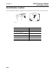
250R/T Operator’s Manual Overview - 2 Serial Number Location Serial Number Location Record serial numbers and date of purchase in spaces provided. Unit serial number is located as shown. ss1129h.
250R/T Operator’s Manual Overview - 3 Intended Use Intended Use The system can be configured to locate pipe and cable or trace non-metallic pipe or conduit. The 250R receiver is configured to operate in twin peak mode with one active frequency (33 kHz) as well as radio, 50P or 60P and 50S or 60S. The 250T transmitter places signals on target lines and is used with 250R units. It is configured to send 33 kHz frequency signals.
Overview - 4 CMW 250R/T Operator’s Manual
250R/T Operator’sManual Foreword - 5 Foreword This manual is an important part of your equipment. It provides safety information and operation instructions to help you use and maintain your Ditch Witch equipment. Read this manual before using your equipment. Keep it with the equipment at all times for future reference. If you sell your equipment, be sure to give this manual to the new owner. If you need a replacement copy, contact your Ditch Witch.
250R/T Operator’s Manual Foreword - 6 250R/T Operator’s Manual Issue number 1.0/OM-10/07 Part number 053-1189 Copyright 2007 by The Charles Machine Works, Inc. , Ditch Witch, CMW, AutoCrowd, Modularmatic, Jet Trac, Roto Witch, Subsite, Fluid Miser, Perma-Soil, Power Pipe, Super Witch, Super Witch II, Pierce Airrow, The Underground, and The Underground Authority Worldwide are registered trademarks of The Charles Machine Works, Inc.
250R/T Operator’s Manual Contents - 7 Contents Overview 1 machine serial number, information about the type of work this machine is designed to perform, basic machine components, and how to use this manual Foreword 5 part number, revision level, and publication date of this manual, and factory contact information Safety 9 machine safety alerts and emergency procedures Controls 13 machine controls and how to use them Locate 21 procedures for locating active, passive and beacon signals Locati
Contents - 8 CMW 250R/T Operator’s Manual
250R/T Operator’s Manual Safety - 9 Safety Chapter Contents Guidelines . . . . . . . . . . . . . . . . . . . . . . . . . . . . . . . . 10 Safety Alert Classifications . . . . . . . . . . . . . . . . . . 10 Safety Alerts . . . . . . . . . . . . . . . . . . . . . . . . . . . . . .
250R/T Operator’s Manual Safety - 10 Guidelines Guidelines • Read and follow all safety precautions. • Do not operate equipment unless you have completed proper training and have read and understood the operator’s manual. • Before operation, ensure the equipment is in proper working order and is not damaged. Any transmitter leads should be checked for damage.
250R/T Operator’s Manual Safety - 11 Safety Alerts Safety Alerts Electric shock. The connection leads may give off an electric shock when plugged into the transmitter. Avoid touching the metal ends of clips when the transmitter is switched on. NOTICE: • Electric shock or equipment damage can result if transmitter is connected to live electrical conductors. Observe all company and national safety procedures. • Turn off transmitter when connecting or moving ground stake.
Safety - 12 250R/T Operator’s Manual Safety Alerts CMW
250R/T Operator’s Manual Controls - 13 Controls Chapter Contents Receiver . . . . . . . . . . . . . . . . . . . . . . . . . . . . . . . . . 14 • Single-Key Controls . . . . . . . . . . . . . . . . . . . . . . . . . . . . . . . . . . . . . . . .14 • Double-Key Controls . . . . . . . . . . . . . . . . . . . . . . . . . . . . . . . . . . . . . . .16 • Display . . . . . . . . . . . . . . . . . . . . . . . . . . . . . . . . . . . . . . . . . . . . . . . . . .17 Transmitter . . . . . . . . . . . . . . . .
250R/T Operator’s Manual Controls - 14 Receiver Receiver Single-Key Controls 1. Mode 4. Down arrow 2. ON/OFF 5. DEPTH 3. Up arrow Item Description Notes 1. Mode To cycle through operating frequencies, press. See “Mode” on page 35.
250R/T Operator’s Manual Controls - 15 Receiver Item Description 2. To turn on, press. ON/OFF Notes To turn off, press again. 3. Up Arrow To increase gain, press. 4. Down Arrow To decrease gain, press. 5. DEPTH To estimate depth of properly located 33 kHz signal, press.
Controls - 16 250R/T Operator’s Manual Receiver Double-Key Controls Item Description DEPTH + Down Arrow To turn on backlight, press indicated keys.
250R/T Operator’s Manual Controls - 17 Receiver Display 1. Gain level 3. Depth 2. Signal strength 4. Mode Item Description Notes 1. Gain Level Graphically indicates gain level. IMPORTANT: Gain increases to the right.
250R/T Operator’s Manual Controls - 18 Receiver Item Description 2. Signal Strength Numerically and graphically indicates the signal strength level. 3. Depth Displays depth estimate of properly located line. 4. Mode Indicates mode setting. CMW Notes See “Mode” on page 35.
250R/T Operator’s Manual Controls - 19 Transmitter Transmitter 1. LEDs 3. Power level 2. On/Off Item Description Notes 1. LEDs Green LED indicates low power. IMPORTANT: If both LEDs are flashing, change batteries. Red LED indicates high power. 2. On/Off To turn on, press. To turn off, press again. si1017a-d.
250R/T Operator’s Manual Controls - 20 Transmitter Item Description 3. Power Level To switch between low and high power, press.
250R/T Operator’s Manual Locate - 21 Locate Chapter Contents Active . . . . . . . . . . . . . . . . . . . . . . . . . . . . . . . . . . . 22 • Setup. . . . . . . . . . . . . . . . . . . . . . . . . . . . . . . . . . . . . . . . . . . . . . . . . . . .22 • Technique . . . . . . . . . . . . . . . . . . . . . . . . . . . . . . . . . . . . . . . . . . . . . . . .25 • Special Situations . . . . . . . . . . . . . . . . . . . . . . . . . . . . . . . . . . . . . . . . . .27 Passive . . . . . . . . . . . . .
250R/T Operator’s Manual Locate - 22 Active Location Active Location Setup Follow setup procedures for the type of locating you will be doing: direct connection, induction clamp, or broadcast induction. Always check receiver battery level at startup. See “Controls” on page 13. Direct Connection Electric shock. The connection leads may give off an electric shock when plugged into the transmitter. Avoid touching the metal ends of clips when the transmitter is switched on.
250R/T Operator’s Manual Locate - 23 Active Location Induction Clamp Electric shock. The connection leads may give off an electric shock when plugged into the transmitter. Avoid touching the metal ends of clips when the transmitter is switched on. NOTICE: • Electric shock or equipment damage can result if transmitter is connected to live electrical conductors. Observe all company and national safety procedures. • Turn off transmitter when connecting or moving ground stake.
Locate - 24 250R/T Operator’s Manual Active Location Broadcast Induction To set up transmitter for broadcast induction: 1. Remove cable, stake, clamp and any other metal objects from transmitter. 2. Place transmitter parallel to and directly above suspected line, as shown. Note: Transmitter must be parallel to object, as shown, in order to produce the best signal. 3. Turn on transmitter.
250R/T Operator’s Manual Locate - 25 Active Location Technique m 5 ft . 7 5 2 ss1131h.eps IMPORTANT: Follow steps 1-3 for all types of active location. For reference, the illustration above shows direct connection method. If using broadcast induction, ensure that transmitter is in line with and above suspected line, as shown on previous page. 1. Walk in an arc approximately 25’ (7.5 m) around transmitter. 2. Hold the receiver as shown. 3.
Locate - 26 250R/T Operator’s Manual Active Location 4. Rotate the receiver to determine which direction the line runs. IMPORTANT: Receiver indicates the best signal when the handle is perpendicular to the target line. 5. Set receiver on the ground. 6. Press depth button when the line has been located. IMPORTANT: When estimating depth for pipe, depth shown is to the center of the pipe. 7. Continue to trace the line and take depth estimates every few paces. 8.
250R/T Operator’s Manual Locate - 27 Active Location Special Situations Situation What to try Signal is lost. Walk in a circle to detect a tee or bend in the line. Signal varies from low to high and is unstable. Mark as a hand-dig area. You are near a power line and are receiving interference. Sweep the area in power mode. If receiver gives a strong signal response, a power line is interfering with transmitter signal. Receiver does not function properly.
250R/T Operator’s Manual Locate - 28 Passive Location Passive Location Setup Turn on receiver and choose power or radio frequency. Always check receiver battery level at startup. NOTICE: Lines with no AC current flowing through them are hard to detect and may be hazardous because they may still have voltage potential. To locate, turn on an appliance to cause current to flow and use active search methods.
250R/T Operator’s Manual Locate - 29 Passive Location Focus the Signal Move receiver over detected signal to find best signal response. Rotate receiver until signal is strongest. Best signal indicates line direction. NOTICE: Keep receiver level. Trace the Line Walk along the suspected path while moving the receiver from side to side across the area. IMPORTANT: Keep receiver handle perpendicular to the suspected line path.
250R/T Operator’s Manual Locate - 30 Passive Location Mark the Line Sweep, focus, and trace all detected signals in the area. Mark line paths with colored paint or flags. See the chart below for standard color markings for line locations. Special Situations Situation What to try Signal is lost. Walk in a circle to detect a tee or bend in the line. Signal varies from low to high and is unstable. Check the transmitter connection.
250R/T Operator’s Manual Locate - 31 Beacon (Sonde) Location Beacon (Sonde) Location Trace metallic or non-metallic pipes or conduits by locating and following a beacon (sonde) signal. IMPORTANT: Large metal objects and other signals (such as railroad signals or overhead power lines) will distort signal. Setup To set up for beacon (sonde) location: 1. Follow instructions for installing beacon (sonde) battery. 2. Turn on receiver to ensure that beacon (sonde) is functioning properly. 3.
Locate - 32 250R/T Operator’s Manual Beacon (Sonde) Location CMW
250R/T Operator’s Manual Locating Concepts - 33 Locating Concepts Chapter Contents Signal Type . . . . . . . . . . . . . . . . . . . . . . . . . . . . . . . 34 • Active . . . . . . . . . . . . . . . . . . . . . . . . . . . . . . . . . . . . . . . . . . . . . . . . . . .34 • Beacon (Sonde) . . . . . . . . . . . . . . . . . . . . . . . . . . . . . . . . . . . . . . . . . . .34 • Passive . . . . . . . . . . . . . . . . . . . . . . . . . . . . . . . . . . . . . . . . . . . . . . . . . .34 Mode . . . . .
Locating Concepts - 34 250R/T Operator’s Manual Signal Type Signal Type The 250R can detect two types of signals: • Active signals are placed on a target line with a transmitter and detected by the receiver. As an option, an active signal from a beacon (sonde) can also be detected by the receiver. • Passive signals reside on the target line and are read by receiver.
250R/T Operator’s Manual Locating Concepts - 35 Mode Mode The 250R receiver has three available mode options. Mode Description Notes Power Allows receiver to trace live power lines. IMPORTANT: Current must be flowing through the line. Radio Allows receiver to trace lines that pick up and radiate very low frequency (VLF) radio waves. Transmitter Allows receiver to trace lines that have had a 33 kHz signal placed on them by a transmitter.
Locating Concepts - 36 250R/T Operator’s Manual Common Signal Problems Common Signal Problems Distortions in the electromagnetic field around a line can affect location accuracy. Tees, bends, parallel lines, crossing lines, or large metallic objects can distort signals. IMPORTANT: If target depth and location are critical, confirm by hand-digging or vacuum excavation.
250R/T Operator’s Manual Service - 37 Service Chapter Contents General Care . . . . . . . . . . . . . . . . . . . . . . . . . . . . . . 38 As Needed . . . . . . . . . . . . . . . . . . . . . . . . . . . . . . . . 38 Transmitter Error Messages . . . . . . . . . . . . . . . . . 39 Receiver Error Messages . . . . . . . . . . . . . . . . . . . .
250R/T Operator’s Manual Service - 38 General Care General Care Under normal operating conditions, receiver needs only minor maintenance. Following these care instructions can ensure longer equipment life: • Do not drop the equipment. • Do not expose the equipment to high heat (such as in the rear window of a vehicle). • Clean equipment with a damp cloth and mild soap. Never use scouring powder. • Do not immerse in any liquid. • Inspect housing daily for cracks or other damage.
250R/T Operator’s Manual Service - 39 Transmitter Error Messages Transmitter Unit Change Batteries Use six D-cell alkaline batteries in transmitter. 1. Open battery cover. 2. Insert batteries as shown. 3. Close cover and tighten battery cover. 4. Check operation. If battery light is flashing when unit is turned on, then one battery is incorrectly installed or batteries are weak.
Service - 40 250R/T Operator’s Manual Receiver Error Messages Receiver Error Messages Three Dashes If three dashes appear in the display when pressing the depth button, one of the following could be possible: • The receiver is detecting a signal above it and cannot estimate depth. This message is usually caused by interfering signals. Try relocating target signal. • Line is too deep for depth estimate. Mark as hand-dig area. • Line is too shallow for depth estimate.
250R/T Operator’s Manual Specifications - 41 250 Receiver Specifications 250 Receiver L W H ss1127h.eps Dimensions U.S. Metric H Height 27.5” 700 mm L Length 11.5” 290 mm W Width 4” 100 mm Weight 5 lb 2.3 kg Operation U.S.
250R/T Operator’s Manual Specifications - 42 250 Transmitter 250 Transmitter W L POWER OUTPUT ON/ OFF H 300 TRANSMITTER ss1128h.eps Dimensions U.S. Metric H Height 9.25” 235 mm L Length 12.25” 311 mm W Width 4.5” 114 mm Weight 5 lb 2.3 kg Operation U.S.
250R/T Operator’s Manual Specifications - 43 System Operation System Operation Operating Modes and Frequencies Active line: 33 kHz Passive line (locate only): 50 Hz or 60 Hz Beacon (Sonde) (locate/depth only): 33 kHz Radio (locate only) Locating Ranges Lines 15’ 4.6 m Beacons (Sondes) 10’ 3m Active line ±5% 0.5-10’ 0.15-3 m Active line ±10% 10’ + 3m+ Beacon (Sonde) ±5% 0.5-10’ 0.
Specifications - 44 250R/T Operator’s Manual System Operation CMW
250R/T Series Operator’s Manual Support - 45 Procedure Support Procedure Notify your dealer immediately of any malfunction or failure of Ditch Witch equipment. Always give model, serial number, and approximate date of your equipment purchase. This information should be recorded and placed on file by the owner at the time of purchase. Return damaged unit to dealer for inspection and warranty consideration if in warranty time frame. All repairs must be done by an authorized Ditch Witch repair facility.
250R/T Series Operator’s Manual Warranty - 46 Limited Product Warranty Policy Warranty Limited Product Warranty Policy Warranty Periods New Product A twelve-month period starts on the date of delivery to the end user: trackers, remote displays, receivers, transmitters, radars, fault finders A six-month period starts on the date of delivery to the end user: directional and locate beacons A three-month period starts on the date of delivery to the end user: accessories: cables, clamps, canoes, bags, and ada
250R/T Series Operator’s Manual Warranty - 47 Limited Product Warranty Policy Details and Exclusions • The warranty includes only Ditch Witch Electronics products and accessories that are manufactured and distributed by Ditch Witch Electronics. The warranty compensates on defects in material or workmanship. • Defects will be determined through inspection by Ditch Witch Electronics or authorized repair centers.
Warranty - 48 250R/T Series Operator’s Manual Limited Product Warranty Policy CMW