50R/T Operator’s Manual CMW® Issue 1.
150R/T Operator’s Manual Overview - 1 Overview Chapter Contents Serial Number Location . . . . . . . . . . . . . . . . . . . . . . 2 Intended Use . . . . . . . . . . . . . . . . . . . . . . . . . . . . . . . 3 About This Manual . . . . . . . . . . . . . . . . . . . . . . . . . . 3 • Bulleted Lists. . . . . . . . . . . . . . . . . . . . . . . . . . . . . . . . . . . . . . . . . . . . . . .3 • Numbered Lists . . . . . . . . . . . . . . . . . . . . . . . . . . . . . . . . . . . . . . . . . . . . .
150R/T Operator’s Manual Overview - 2 Serial Number Location Serial Number Location Record serial numbers and date of purchase in spaces provided. Unit serial number is located as shown.
150R/T Operator’s Manual Overview - 3 Intended Use Intended Use The system can be configured to locate pipe and cable or trace metallic and non-metallic pipe or conduit. The 150R receiver is available in peak or null configurations. Units configured to operate in the peak mode will have one active frequency (640Hz, 30kHz or 83kHz) as well as 60S and 60P. Units configured to operate in null mode will only have one frequency (83kHz).
Overview - 4 150R/T Operator’s Manual FCC Statement FCC Statement This device complies with Part 15 of the FCC Rules. Operation is subject to the following two conditions: (1) this device may not cause harmful interference, and (2) this device must accept any interference received, including interference that may cause undesired operation. Changes or modifications not expressly approved by The Charles Machine Works, Inc. could void the user’s authority to operate the equipment.
150R/T Operator’s Manual Foreword - 5 Foreword This manual is an important part of your equipment. It provides safety information and operation instructions to help you use and maintain your Ditch Witch equipment. Read this manual before using your equipment. Keep it with the equipment at all times for future reference. If you sell your equipment, be sure to give this manual to the new owner. If you need a replacement copy, contact your Ditch Witch.
150R/T Operator’s Manual Foreword - 6 150R/T Operator’s Manual Issue number 1.1/OM-5/07 Part number 053-1104 Copyright 2006, 2007 by The Charles Machine Works, Inc. , Ditch Witch, CMW, AutoCrowd, Modularmatic, Jet Trac, Roto Witch, Subsite, Fluid Miser, Perma-Soil, Power Pipe, Super Witch, Super Witch II, Pierce Airrow, The Underground, and The Underground Authority Worldwide are registered trademarks of The Charles Machine Works, Inc.
150R/T Operator’s Manual Contents - 7 Contents Overview 1 machine serial number, information about the type of work this machine is designed to perform, basic machine components, and how to use this manual Foreword 5 part number, revision level, and publication date of this manual, and factory contact information Safety 9 machine safety alerts and emergency procedures Controls 13 machine controls and how to use them Locate 25 procedures for locating active, passive and beacon signals Locati
Contents - 8 CMW 150R/T Operator’s Manual
150R/T Operator’s Manual Safety - 9 Safety Chapter Contents Guidelines . . . . . . . . . . . . . . . . . . . . . . . . . . . . . . . . 10 Safety Alert Classifications . . . . . . . . . . . . . . . . . . 11 Safety Alerts . . . . . . . . . . . . . . . . . . . . . . . . . . . . . .
Safety - 10 150R/T Operator’s Manual Guidelines Guidelines Follow these guidelines before operating any jobsite equipment: • Complete proper training and read operator’s manual before using equipment. • Classify jobsite based on its hazards and use correct tools and machinery, safety equipment, and work methods for jobsite. • Mark jobsite clearly and keep spectators away. • Wear personal protective equipment.
150R/T Operator’s Manual Safety - 11 Safety Alert Classifications Safety Alert Classifications These classifications and the icons defined on the following pages work together to alert you to situations which could be harmful to you, jobsite bystanders or your equipment. When you see these words and icons in the book or on the unit, carefully read and follow all instructions. YOUR SAFETY IS AT STAKE. Watch for the three safety alert levels: DANGER, WARNING and CAUTION. Learn what each level means.
150R/T Operator’s Manual Safety - 12 Safety Alerts Safety Alerts Electric shock. Contacting electric lines will cause death or serious injury. Know location of lines and stay away. Jobsite hazards could cause death or serious injury. Use correct equipment and work methods. Use and maintain proper safety equipment. Explosion possible. Serious injury or equipment damage could occur. Follow directions carefully. Incorrect procedures could result in death, injury, or property damage.
150R/T Operator’s Manual Controls - 13 Controls Chapter Contents Receiver . . . . . . . . . . . . . . . . . . . . . . . . . . . . . . . . . . 14 • Controls. . . . . . . . . . . . . . . . . . . . . . . . . . . . . . . . . . . . . . . . . . . . . . . . . .14 • Displays. . . . . . . . . . . . . . . . . . . . . . . . . . . . . . . . . . . . . . . . . . . . . . . . . .16 • Menu . . . . . . . . . . . . . . . . . . . . . . . . . . . . . . . . . . . . . . . . . . . . . . . . . . . .19 Transmitter . . . . .
Controls - 14 150R/T Operator’s Manual Receiver Receiver Controls 1. On-off/Cancel 3. Select/Menu 2. Up arrow 4.
150R/T Operator’s Manual Controls - 15 Receiver Item Description 1. On-Off/Cancel To turn on, press. Notes To turn off, press again. To cancel current action in menu mode, press. 2. Up Arrow To increase gain, press. To scroll up menu options in menu mode, press. 3. Select/Menu To access the menu screen, press. To select highlighted menu option, press again. 4. Down Arrow To decrease gain, press. To scroll down menu options in menu mode, press.
Controls - 16 150R/T Operator’s Manual Receiver Displays 1. Signal bar 5. Gain level 2. Gain bar 6. Battery level 3. Signal strength 7. Antenna mode 4. Volume level 8.
150R/T Operator’s Manual Controls - 17 Receiver Item Description 1. Signal Bar Graphically represents the signal strength levels. 2. Gain Bar Graphically represents the gain. Notes Gain increases to the right. 3. Signal Strength Numerically represents the one-hundred and one (0-100) signal strength levels. 4. Volume Level Indicates volume is turned to an on position. 5. Gain Level Numerically represents twenty-one (0-20) gain levels.
150R/T Operator’s Manual Controls - 18 Receiver Item Description 6. Battery Level Indicates battery level. Three segments indicates full battery level. One segment indicates low level. No segments indicates that batteries should be changed soon. 7. Antenna Mode Indicates factory antenna configuration. Unit is factory configured in peak or null mode. 8. Frequency Indicates frequency setting.
150R/T Operator’s Manual Controls - 19 Receiver Menu Select Frequency (Peak Units) IMPORTANT: Receiver units configured to operate in null mode do not have a frequency menu. The 150R has three available active and two passive frequencies: 640Hz, 30kHz, or 83kHz, 60S, and 60P. 1. Press Menu to select frequency setting. 2. Press Menu to select the Frequency option. 3. Use Up Arrow or Down Arrow to highlight the desired frequency.
Controls - 20 150R/T Operator’s Manual Receiver 4. Use Up Arrow or Down Arrow to adjust the volume to the desired level. 5. Press Menu to return to display. IMPORTANT: Maintain a lower volume to conserve battery life. Setup Menu Setup Menu allows operator to select audio mode, adjust contrast and perform a self test. 1. Press Menu to enter setup menu. 2. Press Down Arrow to highlight setup. 3. Press Menu to select Setup.
150R/T Operator’s Manual Controls - 21 Receiver Adjust Contrast Receiver has twenty-five levels of contrast from light to dark. 1. Enter Setup Menu, See “Setup Menu” on page 20. 2. Press Down Arrow to highlight Contrast. 3. Press Menu to enter Contrast menu. 4. Use Up Arrow or Down Arrow to adjust contrast to desired level. 5. Press Menu to return to display.
Controls - 22 150R/T Operator’s Manual Receiver Perform Self Test Receiver performs self test to detect errors. 1. Enter Setup Menu, see “Setup Menu” on page 20. 2. Press Down Arrow to highlight Self Test. 3. Press Menu to perform a self test. 4. Turn off all beacons and transmitters. 5. Press any key to begin test. IMPORTANT: Do not move receiver during test. 6. Receiver will display self test results. • If receiver finds no errors, it will display “All channels passed. Press any key . . . .
150R/T Operator’s Manual Controls - 23 Transmitter Transmitter 1. Power 2. Battery level indicator Item Description 1. Power To deliver high power, move switch up. Notes To deliver low power, move switch down. To turn off, move switch to center.
150R/T Operator’s Manual Controls - 24 Transmitter Item Description Notes 2. Battery Level Indicator Indicates battery level when unit is in high or low position. IMPORTANT: • Solid light indicates sufficient battery level. • Flashing light during operation indicates low battery level. • CMW Flashing light at startup indicates battery level is low or one battery is installed backwards.
150R/T Operator’s Manual Locate - 25 Locate Chapter Contents Active . . . . . . . . . . . . . . . . . . . . . . . . . . . . . . . . . . . 26 • Setup. . . . . . . . . . . . . . . . . . . . . . . . . . . . . . . . . . . . . . . . . . . . . . . . . . . .26 • Technique . . . . . . . . . . . . . . . . . . . . . . . . . . . . . . . . . . . . . . . . . . . . . . . .29 • Special Situations . . . . . . . . . . . . . . . . . . . . . . . . . . . . . . . . . . . . . . . . . .31 Passive . . . . . . . . . . . . .
150R/T Operator’s Manual Locate - 26 Active Location Active Location Setup Follow setup procedures for the type of locating you will be doing: direct connection, induction clamp, or broadcast induction. Always check receiver battery level at startup. See “Controls” on page 13. Direct Connection Jobsite hazards could cause death or serious injury. Use correct equipment and work methods. Use and maintain proper safety equipment.
150R/T Operator’s Manual Locate - 27 Active Location Induction Clamp Jobsite hazards could cause death or serious injury. Use correct equipment and work methods. Use and maintain proper safety equipment. NOTICE: Electric shock or equipment damage can result if transmitter is connected to live cable. Contact qualified utility personnel and follow all standards and requirements for disconnecting and grounding lines. To set up transmitter for use with induction clamp: 1. Plug cable into transmitter (1). 2.
Locate - 28 150R/T Operator’s Manual Active Location Broadcast Induction To set up transmitter for broadcast induction: 1. Remove cable, stake, clamp and any other metal objects from transmitter. 2. Place transmitter parallel to and directly above suspected line as shown. Note: Transmitter must be parallel to object, as shown, in order to produce the best signal. 3. Turn on transmitter. 4. Check battery level indicator.
150R/T Operator’s Manual Locate - 29 Active Location Technique IMPORTANT: Follow steps 1-3 for all types of active location. For reference, the illustration above shows direct connection method. If using broadcast induction, ensure that transmitter is in line with and above suspected line, as shown on previous page. 1. Walk in an arc approximately 25’ (7.5 m) around utility to be located. 2. Hold the receiver so that the handle points toward the transmitter, as shown. 3.
Locate - 30 150R/T Operator’s Manual Active Location 4. Rotate the receiver to determine which direction the line runs. IMPORTANT: Receiver indicates the best signal when the handle lines up with the target line. 5. Trace the line and mark with appropriate flags or paint.
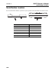
150R/T Operator’s Manual Locate - 31 Active Location Mark the Line Sweep, focus, and trace all detected signals in the area. Mark line paths with colored paint or flags. See the chart below for standard color markings for line locations. Utility Color Marking Symbol electric red -E- gas/oil yellow -G- communications orange -TEL- or -TV- water blue -W- sewer green -S- Special Situations Situation What to try Signal is lost. Walk in a circle to detect a tee or bend in the line.
Locate - 32 150R/T Operator’s Manual Passive Location Passive Location Setup Follow setup procedures for the type of locating you will be doing. Always check receiver battery level at startup. See “Controls” on page 13. NOTICE: Lines with no AC current flowing through them are hard to detect and may be hazardous because they may still have voltage potential. To locate, turn on an appliance to cause current to flow and use active search methods.
150R/T Operator’s Manual Locate - 33 Passive Location Sweep the Site Search the site by walking a grid pattern while holding receiver close to the ground. NOTICE: Keep receiver level. Focus the Signal Move receiver over detected signal to find best signal response. If using a peak antenna mode, rotate receiver until signal is best. Best signal indicates line direction. NOTICE: Keep receiver level.
Locate - 34 150R/T Operator’s Manual Passive Location Antenna Mode Configuration All 150R receiver units can locate in either peak or null mode. Rotate receiver 90° to locate using other antenna mode. When rotated 90°, a peak configured receiver will function as a null receiver or a null configured receiver will function as a peak receiver. IMPORTANT: The operator will not be able to view display in other antenna mode.
150R/T Operator’s Manual Locate - 35 Passive Location Trace the Line Walk along the suspected path while moving the receiver from side to side across the area. IMPORTANT: Keep receiver handle parallel to the suspected line path.
150R/T Operator’s Manual Locate - 36 Passive Location Mark the Line Sweep, focus, and trace all detected signals in the area. Mark line paths with colored paint or flags. See the chart below for standard color markings for line locations. Utility Color Marking Symbol electric red -E- Special Situations Situation What to try Signal is lost. Walk in a circle to detect a tee or bend in the line. Signal varies from low to high and is unstable. Mark as a hand-dig area.
150R/T Operator’s Manual Locate - 37 Beacon Location Beacon Location Trace metallic or non-metallic pipes or conduits by locating and following a beacon signal. IMPORTANT: Large metal objects and other signals (such as railroad signals or overhead power lines) will distort signal. Setup To set up for beacon location: 1. Follow instructions for installing beacon battery. 2. Turn on receiver to ensure that beacon is functioning properly. 3. Attach beacon to plumber’s snake or flex rod. Technique 1.
Locate - 38 150R/T Operator’s Manual Beacon Location CMW
150R/T Operator’s Manual Locating Concepts - 39 Locating Concepts Chapter Contents Signal Type . . . . . . . . . . . . . . . . . . . . . . . . . . . . . . . 40 • Active . . . . . . . . . . . . . . . . . . . . . . . . . . . . . . . . . . . . . . . . . . . . . . . . . . .40 • Beacon . . . . . . . . . . . . . . . . . . . . . . . . . . . . . . . . . . . . . . . . . . . . . . . . . .40 • Passive . . . . . . . . . . . . . . . . . . . . . . . . . . . . . . . . . . . . . . . . . . . . . . . . . .
150R/T Operator’s Manual Locating Concepts - 40 Signal Type Signal Type The 150R can detect three types of signals: • Active signals that are placed on a target line with a transmitter. • An active signal from a beacon. • Passive signals that reside on the target line. Active There are three ways to place active signals on a target line with a transmitter: • Direct connection (preferred method) requires a connection to be made directly onto target line.
150R/T Operator’s Manual Locating Concepts - 41 Antenna Configuration Antenna Configuration The 150R receiver is available with one of two antenna configurations: peak or null. Peak Uses a horizontal antenna to detect signal. Response is highest at strongest signal. Null Uses a vertical antenna to detect signal. Search width is narrower than peak. Response is lowest when receiver is over the line.
Locating Concepts - 42 150R/T Operator’s Manual Common Signal Problems Common Signal Problems Distortions in the electromagnetic field around a line can affect location accuracy. Tees, bends, parallel lines, crossing lines, or large metallic objects can distort signals. IMPORTANT: If target depth and location are critical, confirm by hand-digging or vacuum excavation.
150R/T Operator’s Manual Service - 43 Service Chapter Contents General Care . . . . . . . . . . . . . . . . . . . . . . . . . . . . . . 44 As Needed . . . . . . . . . . . . . . . . . . . . . . . . . . . . . . . . 44 Self Test Error Messages . . . . . . . . . . . . . . . . . . . . 46 Receiver Error Messages . . . . . . . . . . . . . . . . . . . .
150R/T Operator’s Manual Service - 44 General Care General Care Under normal operating conditions, receiver and transmitter need only minor maintenance. Following these care instructions can ensure longer equipment life: • Do not drop the equipment. • Do not expose the equipment to high heat (such as in the rear window of a vehicle). • Clean equipment with a damp cloth and mild soap. Never use scouring powder. • Do not immerse in any liquid. • Inspect housing daily for cracks or other damage.
150R/T Operator’s Manual Service - 45 As Needed Transmitter Unit Change Batteries Use six C-cell alkaline batteries in transmitter. 1. Open battery cover. 2. Insert batteries as shown. IMPORTANT: Do not mix new and used batteries. 3. Close and tighten battery cover. 4. Check operation. If battery light is flashing when unit is turned on, then one battery is incorrectly installed or batteries are weak.
Service - 46 150R/T Operator’s Manual Self Test Error Messages Self Test Error Messages A receiver self test may return an error message for four reasons: low sensitivity, a failed channel, noise present, or gain test failure. Low Sensitivity A low sensitivity message will always appear together with a “noise” screen. This could indicate a problem with the antenna, or it could simply be the result of attempting to test in a noisy environment. Try the test again later, preferably in a different location.
150R/T Operator’s Manual Specifications - 47 150 Receiver Specifications 150 Receiver Dimensions U.S. Metric H Height 2.37” 6.02 cm L Length 12” 30.48 cm W Width 4.37” 11.01 cm Weight 2 lb 0.
Specifications - 48 150R/T Operator’s Manual 150 Transmitter 150 Transmitter Dimensions U.S. Metric H Height 3.43” 8.71 cm L Length 12” 30.48 cm W Width 6.25” 15.88 cm Weight 3 lb 1.
150R/T Operator’s Manual Specifications - 49 System Operation System Operation Operation U.S. Metric Operating temperature range -4° F to122° F -20° C to 50° C Antenna configurations peak, null Audio output speaker Operating modes (some optional) Active line 30kHz, 83kHz Passive line 60Hz (60P), 180Hz (60S) Beacon 640Hz, 30kHz Depth Estimate Tolerances* 150 beacon (640H) in air 12’ 3.66 m 150 beacon (640H) in cast iron 6’ 1.83 m 150 (30k) beacon in air 12’ 3.
Specifications - 50 150R/T Operator’s Manual System Operation CMW
150R/T Operator’s Manual Support - 51 Procedure Support Procedure Notify your dealer immediately of any malfunction or failure of Ditch Witch equipment. Always give model, serial number, and approximate date of your equipment purchase. This information should be recorded and placed on file by the owner at the time of purchase. Return damaged unit to dealer for inspection and warranty consideration if in warranty time frame. All repairs must be done by an authorized Ditch Witch repair facility.
150R/T Operator’s Manual Warranty - 52 Limited Product Warranty Policy Warranty Limited Product Warranty Policy Warranty Periods New Product A twelve-month period starts on the date of delivery to the end user: trackers, remote displays, receivers, transmitters, radars, fault finders A six-month period starts on the date of delivery to the end user: directional and locate beacons A three-month period starts on the date of delivery to the end user: accessories: cables, clamps, canoes, bags, and adapters U
150R/T Operator’s Manual Warranty - 53 Limited Product Warranty Policy Details and Exclusions • The warranty includes only Ditch Witch Electronics products and accessories that are manufactured and distributed by Ditch Witch Electronics. The warranty compensates on defects in material or workmanship. • Defects will be determined through inspection by Ditch Witch Electronics or authorized repair centers.
Warranty - 54 150R/T Operator’s Manual Limited Product Warranty Policy CMW