
User Manual
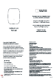

Cloud Connector
Getting Started
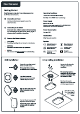
Connecting to Power
Cloud Connectors relay data from wireless sensors into
the DT cloud infrastructure.
Use the provided power supply to power the
Cloud Connector.
1
If the device has a cellular modem it will automatically
start connecting to the cloud service. If not, plug in an
ethernet cable to establish a connection.
Connecting to the Cloud
2
Operating Condition
Temperature: 0 to 50°C (32 to 122°F
Humidity: 10 to 90%RH (non-condensing
Power Suppl
External DC, 5V 2
Only use a power supply compliant to EN or IEC 62368-1:2014
or later with ES1 and PS2 or PS1 classicatio
Power Consumptio
Average < 3
Constructio
IP20, Polycarbonate (PC
Symbols
Conformité Européenn
(Valid for EU version)
UK Conformity Assesse
(Valid for EU version)
Federal Communications
Commission
(Valid for US version)
W
aste of Electrical and
Electronic E
q
uipment
B
arrel
J
ac
k
Polarit
Center Positive
U
L
Certie
(Valid for US version)
3
Obser
v
e the Status
I
ndicator
Connected to the Internet and fully operational.
Solid
W
hite
Not connected, visit d21s.com
/
help for troubleshooting.
Solid
R
ed
Pulsing
W
hite
Connecting
/
updating, this can ta
k
e up to a few minutes.
W
all Installation
Secure the mounting brac
k
et
to the wall with screws
If mounted below 2 meters,
the adhesive can be used alone.
The Cloud Connector
attaches to the brac
k
et with
a friction bayonet mount.
Align the slots and mount the
Cloud Connector onto the
brac
k
et.
Turn the Cloud Connector 45°
degrees to secure it in place
Connect the power cable (and
ethernet cable for ethernet
version).
Remove the tile from the
ceiling to perform the
installation
The mounting brac
k
et is
attached to the tile using the
provided bac
k
ing plate with
two screws and nuts
The Cloud Connector
attaches to the brac
k
et with
a friction bayonet mount.
Drop Ceiling Installation
Drill a 15 mm hole
6 cm from edge of
the device for
cables.