
Data Sheet

2
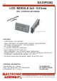
EA DIPS082
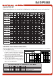
PINOUT
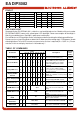
TABLE OF COMMANDS
Instruction
Code
Description
Execut
e
Time
(max.)
RS
R/W
DB
7
DB
6
DB
5
DB
4
DB
3
DB
2
DB
1
DB
0
Clear Display 0 0 0 0 0 0 0 0 0 1
Clears all display and returns the cursor
tothehomeposition(Address0).
1.64ms
Cursor At Home 0 0 0 0 0 0 0 0 1 *
Returns the Cursor to the home
position (Address 0). Also returns the
display being shifted to the original
position. DD RAM contents remain
unchanged.
1.64ms
Entry Mode Set 0 0 0 0 0 0 0 1 I/D S
Sets the Cursor move direction and
specifies or not to shift the display.
These operation are performed during
data write and read.
40µs
Display On/Off
Control
0 0 0 0 0 0 1 D C B
Sets ON/OFF of all display (D) cursor
ON/OFF (C), and blink of cursor position
character (B).
40µs
C
ursor / Display Shift 0 0 0 0 0 1
S/C R/L
* *
Moves the Cursor and shifts the display
without changing DD RAM contents.
40µs
Function Set 0 0 0 0 1 DL N F * *
Sets interface data length (DL) number
of display lines (N) and character font
(F).
40µs
C
G RAM Address Set 0 0 0 1 ACG
Sets the CG RAM address. CG RAM
data is sent and received after this
setting.
40µs
D
D RAM Address Set 0 0 1 ADD
Sets the DD RAM address. DD RAM
data is sent and received after this
setting.
40µs
Busy Flag / Address
Read
0 1 BF AC
Reads Busy flag (BF) indicating internal
operation is being performed and reads
address counter contents.
-
CG RAM / DD RAM
Data write
1 0 Write Data
Writes data into DD RAM or CG RAM
40µs
CG RAM / DD RAM
Data Read
1 1 Read Data
Reads data from DD RAM or CG RAM
40µs
Pin Symbol Level Function Pin Symbol Level Function
1 VSS L Power Supply 0V (GND) 8 D1 H/L Display Data
2 VDD H Power Supply+5V 9 D2 H/L Display Data
3 VEE - Contrast (about 0.3V / 1.2V) 10 D3 H/L Display Data
4 RS H/L H=Data / L=Command 11 D4 (D0) H/L DisplayData
5 R/W H/L H=Read / L=Write 12 D5 (D1) H/L DisplayData
6 E H Enable (falling edge) 13 D6 (D2) H/L DisplayData
7 D0 H/L Display Data / Anode LED-B/L 14 D7 (D3) H/L Display Data, MSB
LED BACKLIGHT
Standard display EA DIPS082-HN is reflective, non-backlighted version. Module with part number
EA DIPS082-HNLED comes with yellow/green LED backlight. Power consumption for backlight is
50mA typ. and 80mA max. Backlight is permanent switched on.
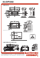
For individual use LED backlight can be switched on and off after doing the following modification:
Remove series resistor R5 and close solder link LB. Now a positive voltage at pin 7 (D0) powers Anode
of backlight direct. To limit LED-current an external series resistor is required (R
Ext.
= 0,8V / I
LED
). Please
note that in this case display interface is 4-bit mode only !