
Data Sheet
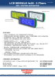

EA DIP203-4
Page 2
ELECTRONIC ASSEMBLY reserves
the right to change specifications
without prior notice. Printing and
typographical errors reserved.
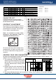
PINOUT
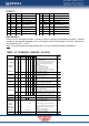
TABEL OF COMMAND (SSD1803, IE=HIGH)
Instruction
C ode
Description
Execute
Time
(270kHz)
RE
Bit
RS R/W
DB
7
DB
6
DB
5
DB
4
DB
3
DB
2
DB
1
DB
0
Clear Display * 0 0000 0 0 0 0 1
Clears all display and returns the cursor to the
home position (Address 0).
1.53ms
Cursor At Home 0 0 0000 0 0 0 1 *
Returns the Cursor to the home position (Address
0). Also returns the display being shifted to the
original position. DD RAM contents remain
unchanged.
1.53ms
Power Down
Mode
1
0 0000 0 0 0 1 PD
Set Power down mode bit.
PD=0: powerdown mode disable
PD=1: powerdown mode enable
39µs
Entry Mode Set
0 0 0 0 0 0 0 0 1 I/D S
Cursor moving direction (I/D=0: dec; I/D=1: inc)
shift enable bit (S=0: disable; S=1: enable shift)
39µs
1 0 0 0 0 0 0 0 1 1 BID
Segment bidirectional function
(BID=0: Seg1->Seg60; BID=1: Seg60->Seg1)
39µs
Display On/Off
Control
0 0 0 0 0 0 0 1 D C B
D=0: display off; D=1: display on
C=0: cursor off; C=1: cursor on
B=0: blink off; B=1: blink on
39µs
extended
Function Set
1 0 0 0 0 0 0 1 FW BW NW
FW=0: 5-dot font width; FW=1: 6-dot font width
BW=0: normal cursor; BW=1: inverting cursor
NW=0: 1- or 2-line (see N); NW=1: 4-line display
39µs
Cursor / Display
Shift
0 0 0 0 0 0 1
S/C R/L
* *
Moves the Cursor or shifts the display
S/C=0: cursor Shift; S/C=1: display shift
R/L=0: shift to left; R/L=1: shift to right
39µs
Scroll Enable 1 0 0 0 0 0 1 H4 H3 H2 H1
Determine the line for horizontal scroll
39µs
Function Set
0 0 0 0 0 1 DL N RE DH RE
sets interface data length (DL=0:4-bit; DL=1:8-bit)
number of display lines (N=0: 1-line; N=1: 2-line)
extension register (RE= 0/1)
scroll/shift (DH=0: dot scroll; DH=1: display shift)
reverse bit (REV=0:normal; REV=1:inverse display)
39µs
1 0 0 0 0 1 DL N RE BE LP
CG-/SEG-RAM blink (BE=0: disable; BE=1: enable)
LP=0: normal mode; LP=1: low power mode
39µs
CG RAM
Address Set
0 0 0 0 1 AC
Sets the CG RAM address. CG RAM data is sent
and received after this setting.
39µs
SEG RAM
Address Set
1 0 0 0 1 *
*
AC
Sets the SEG RAM address. SEG RAM data is sent
and received after this setting.
39µs
DD RAM
Address Set
0
0 01 AC
Sets the DD RAM address. DD RAM data is sent
and received after this setting.
39µs
Set Scroll
Quantity
1
0 01 *
SQ
Sets the quantity of horizontal dot scroll (DH=0) 39µs
Busy Flag /
Address Read
*
0 1BF AC
Reads Busy flag (BF) indicating internal operation is
being performed and reads address counter
contents.
-
Write Data * 1 0 Write Data
Writes data into internal RAM
(DD RAM / CG RAM / SEGRAM)
43µs
Read Data * 1 1 Read Data
Reads data from internal RAM
(DD RAM / CG RAM / SEGRAM)
43µs
BACKLIGHT
Using the LED backlight requires a current source or external current-limiting resistor. Forward
voltage for yellow/green backlight is 3.9~4.2V and for white LED backlight is 3.0~3.6V. Please take
care of derating for T
a
>+25°C.
Note: Do never connect backlight directly to 5V; this may destroy backlight immediately !
Pin Symbo Level Function Pin Symbo Level Function
1 VSS L Power Supply 0V (GND) 10 D3 H / L Display Data
2 VDD H Power Supply +3.3V 11 D4 (D0) H / L Display Data
3 VEE - Contrast adjustment, input 12 D5 (D1) H / L Display Data
4 RS (CS) H / L H=Data, L=Command 13 D6 (D2) H / L Display Data
5
R/W
(SID)
H / L H=Read, L=Write 14 D7 (D3) H / L Display Data, MSB
6 E (SCLK) H Enable (falling edge) 15 - - NC (see EA DIP122-5N)
7 D0 (SOD) H / L Display Data, LSB 16 RES L Reset (internal Pullup 10k)
8 D1 H / L Display Data 17 A - LED B/L+ Resistor required
9 D2 H / L Display Data 18 C - LED B/L-