
Datasheet


DEM 40271 SYH-LY Product Specification
Version: 1.1.0 PAGE: 4
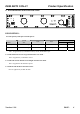
6. PCB DRAWING AND DESCRIPTION.
DESCRIPTION:
6-1-1.The polarity of the pin 15 and the pin 16 :
LED Polarity
symbol
symbol
state
J3,J5 J2,J4
15 Pin 16 Pin
J2,J4 Each solder-bridge Each open Each closed Anode Cathode
J3,J5 Each solder-bridge Each closed Each open Cathode Anode
Note : In application, J3, J5 should be closed , and J2 ,J4 should be open.
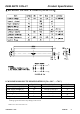
6-1-2.The metal-bezel is set be on ground when the J1 is closed . .
Note: In application ,J1 should be closed.
6-1-3.The LED resistor should can be bridged when the J6 is closed.
Note: In application J6 should be opened.
6-1-4.The R7 and the R8 are the LED resistor.
Note: In application, R7=R8=10 Ohm