
Datasheet


DEM 20232 SYH-LY Product Specification
Version: 3.1.0 PAGE: 4
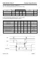
5. PIN ASSIGNMENT
Pin No. Symbol Function
1 VSS Ground
2 VDD Power supply
3 V0 Power Supply for LCD
4 RS Select Display Data("H") or Instructions("L")
5 R/W Read or Write Select Signal
6 E Read/Write Enable Signal
7 DB0
8 DB1
9 DB2
10 DB3
11 DB4
12 DB5
13 DB6
14 DB7
Display Data Signal
15 LED – (K) Please also refer to 6. PCB drawing and description.
16 LED + (A) Please also refer to 6. PCB drawing and description.
6. PCB DRAWING AND DESCRIPTION
Note:The part no. DEM20232 is printed on the PCB.
DESCRIPTION:
6-1-1.The polarity of the pin 15 and the pin 16
LED Polarity
symbol
symbol
state
J3,J5 J2,J4
15 Pin 16 Pin
J2,J4 Each solder-bridge Each open Each Closed Cathode Anode
J3,J5 Each solder-bridge Each Closed Each open Anode Cathode
6-1-2.The metal-bezel should be on ground when the J1 is solder-Bridge.
6-1-3.The LED resistor should be bridged when the J6 is solder-Bridge.
6-1-4.The R7 and the R8 are the LED resistor. R7=R8=5.6ohm