
Datasheet


DEM 16216 SBH-PW-N Product Specification
Version: 1.1.1 PAGE: 5
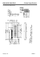
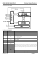
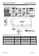
6. PCB DRAWING AND DESCRIPTION
6.1 PCB DRAWING
DESCRIPTION:
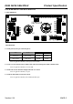
6-1-2.The polarity of the pin 15and the pin 16:
LED Polarity
J3,J5 J2, J4
15 Pin 16 Pin
Each open Each closed Anode Cathode
Each closed Each open Cathode Anode
Note: In application module, J2=J4=open, J3=J5=0 Ohm
6-1-3. The J1 is metal-bezel GND to module GND and J6 is mounting holes GND to module GND.
Note: In application module, J1= J6=0 Ohm.
6-1-4.The LED resistor should be bridged when the J7 is closed.
Note: In application module, J7=open.
6-1-5.The R7, R8 and R9 are the LED resistor.
Note: In application module, R7=33 Ohm, R8=R9=open.