
Datasheet


DEM 16227 SYH-LY Product Specification
VERSION: 2 PAGE: 20
customer and specified in the mechanical
drawing and/or component specifications,
their specifications must conform to those of
the suppliers; otherwise they shall be
rejected.
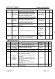
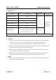
6.6 Connector and other components
No. Defects Description
Acceptance
standard
MAJ
MIN
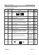
6.6.1
Out of
Specificatio
n
The specification of connector and other
components do not conform to the drawing.
Reject √
6.6.2
Position and
order
Solder position and Pin# 1 should be in the
positions specified by the drawing.
Reject √
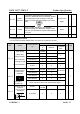
6.6.3 Appearance
1)Flux on PCB components and pins.
2)The pin width of a PIN connector exceeds
½ of the specified pin width.
Reject √
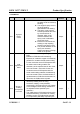
6.6.4 Glue amount
Flat cable connector: as the conducted wire
fixed with glue, if the glue not fully covered
the exposed wire and the copper part around
holes will be rejected.
Reject √
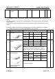
6.6.5
Through
holes
blocked
Socket connector: the components can not
plug-in units as the through holes blocked
and deformation; the locks which with lock
catch can not make the external connector to
be locked.
Reject √
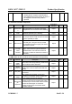
6.7 SMT (Refer to IPC-A-610E the second standard if not specified)
No. Defects Description
Acceptance
standard
MAJ MIN
6.7.1
Soldering
solder
defects
Cold, false and missing soldering, solder crack
and insufficient solder dissolution.
Reject √
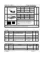
6.7.2
Solder
ball/splash
Solder ball/tin dross causing short circuit at the
solder point. There are active solder ball and
splash.
Reject √
6.7.3 DIP parts
Floated or tilted DIP parts, keypad, and
connectors.
Reject √
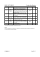
6.7.4
Solder
shape
The welded spot should be concave and
excessive or insufficient solder or solder burr
on the welded spot must be rejected.
Reject √
6.7.5
Component
pin
exposure
For the DIP type components, 0.5~2mm
component pin must be remained after cutting
the soldered pin and the solder surface neither
should not be damaged nor should the
component pin is fully covered with solder;
otherwise rejected.
Reject √