
Datasheet


DEM 16217 SYH-LY-CYR22 Product Specification
Version: 3 PAGE: 5
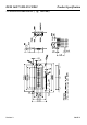
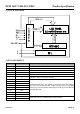
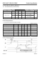
6. PCB DRAWING AND DESCRIPTION
6.1 PCB Drawing
Note: The PCB drawing just for reference!
Description:
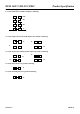
6-1-1.The polarity of the pin 15 and the pin 16
LED Polarity
J3,J5 J2, J4
15 Pin 16 Pin
Each open Each closed Anode Cathode
Each closed Each open Cathode Anode
Note: In application module, J2=J4=Open, J3=J5=0 Ohm.
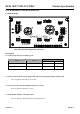
6-1-2. The J1 is metal-bezel GND to module GND and J6 is mounting holes GND to module GND.
Note: In application module, J1= J6=0 ohm.
6-1-3.The LED resistor should be bridged when the J7 is closed.
Note: In application module, J7= Open.
6-1-4.The R8, R9 and R10 are the LED resistor.
Note: In application module, R8=8.2 Ohm, R9=R10=Open.