
Installation Guide

3
discoverbattery.com
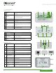
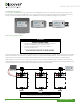
2.1 Physical Features
LYNK Front Face
1
AEbus
Solid Green LED: Communicating with Devices
on AEbus.
2
Memory
Default: OFF, Flashing Green LED: Communicating
with USB Thumb Drive, Solid Green LED: Safe to
remove USB Thumb Drive.
3
Reset Pinhole used to power cycle LYNK.
4
USB
USB Host used for thumb drive to load Firmware
into LYNK.
5
SOC
10 Blue LEDs: Battery bank state of charge,
Single LED Race Sequence: Power, but no AEbus
detected.
6
Mounting Screws
M3 screws used to mount LYNK to Wall or Gang
Mount plate (Included).
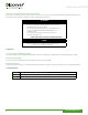
LYNK Back Face
7
MAC Address Unique MAC Address.
8
Serial Number Unique serial number.
9
DIN Rail Hardware
Receptacles
Threaded receptacles used to secure DIN Rail
mounting hardware.
10
Edge Card Cover
Screws
6-32 screws used to secure cover.
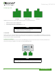
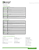
LYNK Bottom Face
11
AEbus
RJ45 Port for CAT5 cable to connect to AEbus
network. This is a terminated connection.
12
Ethernet Future Functionality.
13
Edge Card Slot 0 Slot for universal or Slot 0 Edge Cards.
14
Edge Card Slot 0
Communication Status
Solid Green LED: Communication connection
good.
15
Edge Card Slot 1 Slot for universal or Slot 1 Edge Cards.
16
Edge Card Slot 1
Communication Status
Solid Green LED: Communication connection
good.
17
Edge Card Cover RJ45
Cover to be used with Edge Cards populated
with RJ45 ports.
18
Edge Card Cover Blank Cover to be used when no Edge Card is present.
19
Edge Card Cover
Phoenix
Cover to be used with Edge Cards populated with
Phoenix ports.
20
DC-DC AEBus Power
Converter
Converts nominal DC voltage (24-48V) of AES
Battery to nominal DC 12V to power LYNK,
1 2 3 456
11 1213 15
14 16
1817 19
8 79
10
20
Preliminary 20190314