
User Manual


#4 -13511 Crestwood Place, Richmond, BC, V6V 2E9, Canada + 1.778.776.3288 info@discoverbattery.com
discoverbattery.com
885-0001 REV C
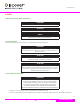
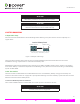
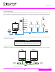
4.2 Battery DC and Communication Connections
ITEM DESCRIPTION
1
COM1 AEBus interface to connect to AES
enabled devices
2
COM2 Xanbus interface port to connect
to Conext System
3 USB interface for PC connectivity
4
On-Off when battery is enabled blue
power light will be illuminated
5
Battery Positive (+) (red) DC terminal
connects to the positive bus bar of the
DC Switchgear
6
Battery Negative (-) (black) DC terminal
connects to the negative bus bar of the DC
Switchgear
Figure 2. Xanbus enabled AES battery connections
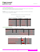
▲ WARNING
FIRE AND BURN HAZARD. Without exception, product
experiencing terminal burn out will not be warranted.
M8” bolt (supplied with battery)
Copper compression lug
Shrink-wrap to
color-code the cable
Terminal surface
Lock washer (supplied with battery)
Flat washer (supplied with battery)
Battery cable lug
Ensure nothing is
between the terminal
surface and the battery
cable lug
Figure 3. Correct Battery Cable and Terminal Connection
TERMINAL TORQUE
9 Nm / 6.64 ft-lb
4.3 Battery Location
Locate the batteries close to the inverter in order to minimize the length of the battery cables. However, care
should be taken to ensure two feet of clearance above the batteries is maintained for access to both battery and
inverter connections and disconnects.
The batteries performance and service life will be optimized when operating in an ambient temperature of
15°C-25°C (59°F-77°F).
4.4 Battery Connection and Conguration
Refer to wiring diagrams (Section 9). To ensure proper balancing and load sharing between parallel batteries ALL
battery cable lengths should be kept the same.
09